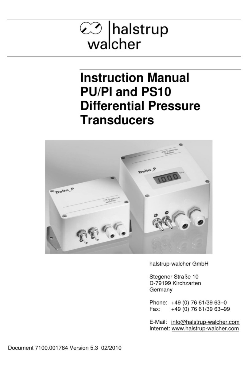
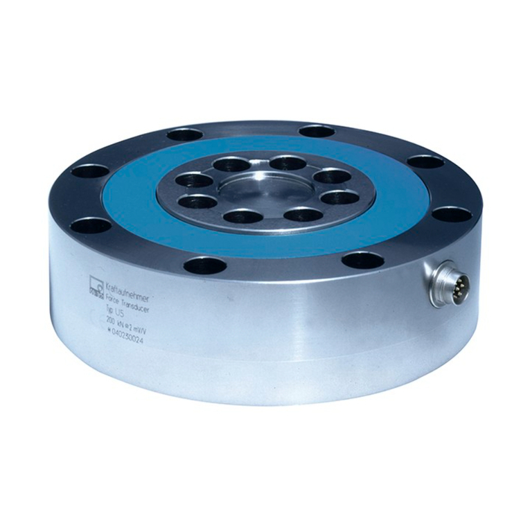
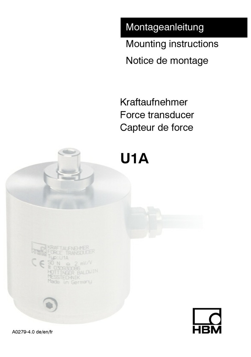
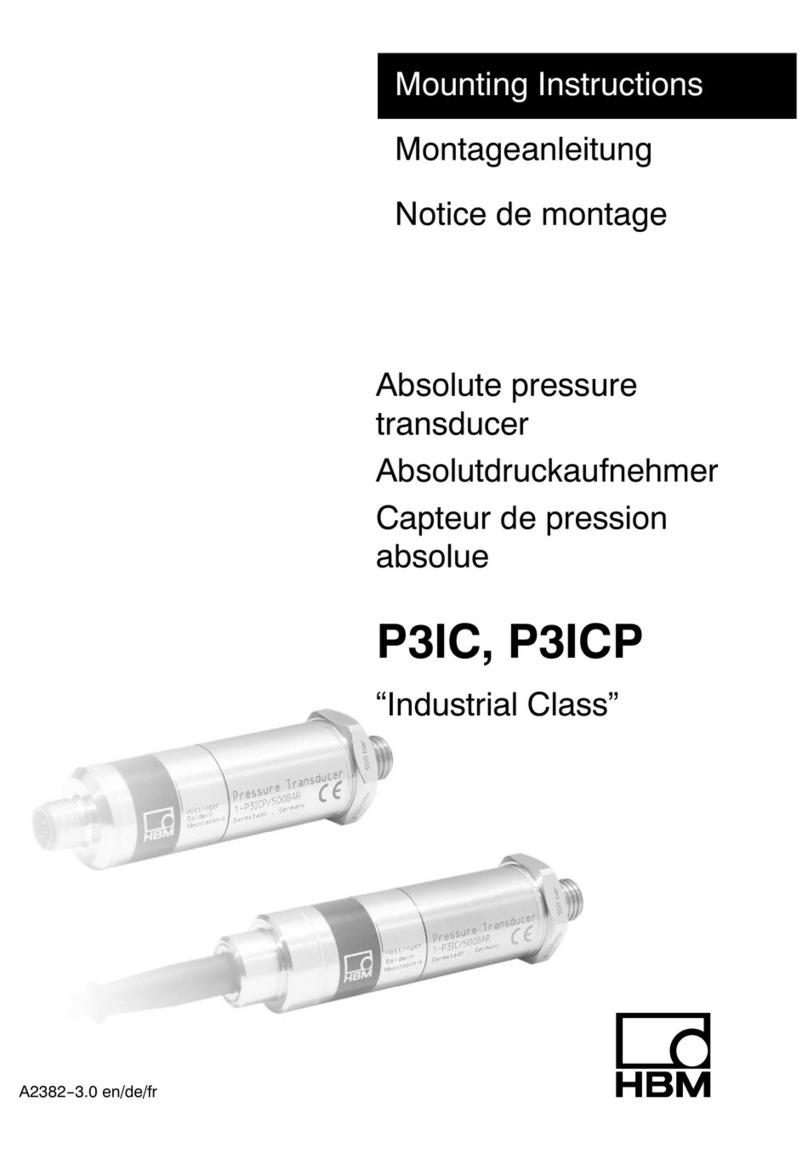
HBM P3MB User manual

A2239-3.0 en/de/fr
Absolut pressure
transducer
Absolutdruckaufnehmer
Capteur de pression
absolue
P3MB, P3MBP
P3 Top Class
Mounting Instructions
Montageanleitung
Notice de montage

English Page 3 - 28. . . . . . . . . . . . . . . . . . . . . . . . . . . . . . . . . . . . . . . . . . . . . . . . .
Deutsch Seite 29 - 54. . . . . . . . . . . . . . . . . . . . . . . . . . . . . . . . . . . . . . . . . . . . . . .
Français Page 55 - 79. . . . . . . . . . . . . . . . . . . . . . . . . . . . . . . . . . . . . . . . . . . . . . .

3
P3…/P3 Top Class
A2239-3.0 en/de/fr HBM
Contents Page
English
Safety instructions 4. . . . . . . . . . . . . . . . . . . . . . . . . . . . . . . . . . . . . . . . . . . . . .
1 Scope of supply 8. . . . . . . . . . . . . . . . . . . . . . . . . . . . . . . . . . . . . . . . . . . . .
2 Application 9. . . . . . . . . . . . . . . . . . . . . . . . . . . . . . . . . . . . . . . . . . . . . . . . . .
2.1 Application in potentially explosive atmospheres 9. . . . . . . . . . . . .
3 Structure and mode of operation 10. . . . . . . . . . . . . . . . . . . . . . . . . . . . . .
4 Installation 11. . . . . . . . . . . . . . . . . . . . . . . . . . . . . . . . . . . . . . . . . . . . . . . . . .
5 Electrical connection 14. . . . . . . . . . . . . . . . . . . . . . . . . . . . . . . . . . . . . . . . .
5.1 Cable extension 16. . . . . . . . . . . . . . . . . . . . . . . . . . . . . . . . . . . . . . . . .
5.2 TEDS transducer identification 17. . . . . . . . . . . . . . . . . . . . . . . . . . . . .
6 Circuit for differential pressure measurement 19. . . . . . . . . . . . . . . . . .
7 Measurement 20. . . . . . . . . . . . . . . . . . . . . . . . . . . . . . . . . . . . . . . . . . . . . . . .
7.1 Measuring dynamic pressures 20. . . . . . . . . . . . . . . . . . . . . . . . . . . . .
8 Specifications (to DIN 16 086) 21. . . . . . . . . . . . . . . . . . . . . . . . . . . . . . . . .
9 Dimensions 25. . . . . . . . . . . . . . . . . . . . . . . . . . . . . . . . . . . . . . . . . . . . . . . . .
10 Options 27. . . . . . . . . . . . . . . . . . . . . . . . . . . . . . . . . . . . . . . . . . . . . . . . . . . . .

P3…/P3 Top Class
4
A2239-3.0 en/de/frHBM
Safety instructions
Appropriate use
The electrically measuring pressure transducer is a pressure‐bearing piece of
equipment and is to be used exclusively for pressure measurement tasks and
directly related control tasks. Use for any purpose other than the above is
deemed to be inappropriate.
In the interests of safety, the device should only be operated as described in
the Operating Manual. It is also essential to comply with the legal and safety
requirements for the application concerned during use. The same applies to
the use of accessories.
Each pressure‐bearing system is an energy store, particularly when the
pressure‐transmitting medium is compressible or the more it is compressed
and even more so, when the pressure medium has a high compressed volume.
If the measurement medium is released unexpectedly and forces are released
from the stored energies, this could pollute the environment, destroy
equipment or cause personal injury.
If a fine steam of hydrocarbon escapes and atomizes into the environment,
then this could lead to an explosion, even with media such as hydraulic oil,
which are usually quite harmless.
The device with its low product of pressure and volume
"PS [bar]*V[l]" complies with the basic safety requirements as per Annex I of
the "Pressure Equipment Directive 97/23/EC" and therefore conforms to
recognized engineering regulations.
It is not appropriate for use as an "accessory with a safety function", in
accordance with the regulations and this must be assessed by the user (within
the meaning of Pressure Equipment Directive 97/23/EC) for the particular
situation.
Proper and safe operation of this pressure transducer requires proper
transportation, correct storage, installation and mounting and careful operation.

5
P3…/P3 Top Class
A2239-3.0 en/de/fr HBM
General dangers of failing to follow the safety instructions
The pressure transducer corresponds to the state of the art and is failsafe.
The device may give rise to remaining dangers if it is inappropriately installed
and operated by untrained personnel.
Any person instructed to carry out installation, commissioning, maintenance or
repair of the device must have read and understood the Operating Manual and
in particular the technical safety instructions.
Accident prevention
You must make sure that the line is not under pressure when installing or
removing the pressure transducer.
Conversions and modifications
The pressure transducer must not be modified from the design or safety
engineering point of view except with our express agreement. Any modification
shall exclude all liability on our part for any damage resulting therefrom.
Qualified personnel
The pressure transducer is only to be installed and used by qualified
personnel, strictly in accordance with the specifications and with the safety
rules and regulations which follow. It is also essential to comply with the legal
and safety requirements for the application concerned during use. The same
applies to the use of accessories.
Qualified personnel means persons entrusted with the installation, assembly,
commissioning and operation of the product, who possess the appropriate
qualifications for their function.
Once the pressure device has been mounted, it must be tested.
The manometers themselves are not systems that need monitoring, but if
necessary, recurrent testing can be carried out by competent personnel (bP) as
per §10 of the European Health and Safety at Work Act (BetrSichV).
Recalibration and repair
When you send the transducer back to HBM for calibration or repair, please
specify which pressure medium is being used. It is always possible that
residual medium could be trapped in the measurement aperture. We need this
information so that we can take appropriate action and choose the correct
cleaning agent, where necessary. If we do not know the media, we may have
to refuse to calibrate or repair.

P3…/P3 Top Class
6
A2239-3.0 en/de/frHBM
Remaining dangers
The scope of supply and performance of the transducer covers only a small
area of measurement technology. In addition, equipment planners, installers
and operators should plan, implement and respond to the safety engineering
considerations of pressure measurement technology in such a way as to
minimize remaining dangers. Prevailing regulations must be complied with at
all times. There must be reference to the remaining dangers associated with
pressure measurement technology.
Although the transducer is designed for maximum safety, safety engineering
regulations demand that burst protection is implemented around the
transducer. This is particularly important for frequent or dynamic loading.
The transducer must be protected against mechanical stresses or knocks. The
resistance of the steel of the measuring body only applies if temperatures are
never allowed to fall below or rise above the limits specified in the data sheet.
If these temperature limits are exceeded, in the event of fire, for example, the
transducer will be unusable.
If, during operation the zero signal changes by more than 5% (with no change
in the ambient conditions), the user should check the transducer to make sure
that it is not being overloaded (and causing the transducer characteristic to
vary).
Remaining dangers are indicated in this Operating Manual by the following
symbols:
Symbol: DANGER
Meaning: Maximum danger level
Warns of an imminently dangerous situation in which failure to comply with
safety requirements will result in death or serious physical injury.
Symbol: WARNING
Meaning: Possibly dangerous situation
Warns of a potentially dangerous situation in which failure to comply with
safety requirements can result in death or serious physical injury.

7
P3…/P3 Top Class
A2239-3.0 en/de/fr HBM
Symbol: CAUTION
Meaning: Potentially dangerous situation
Warns of a potentially dangerous situation in which failure to comply with
safety requirements could result in damage to property or some form of bodily
injury.
Symbols pointing out notes on use and waste disposal as well as useful
information:
Symbol: NOTE
Means that important information about the product or its handling is being
given.
Symbol:
Meaning: CE mark
The CE mark enables the manufacturer to guarantee that the product complies
with the requirements of the relevant EC directives (the Declaration of
Conformity can be found at http://www.hbm.com/HBMdoc).

P3…/P3 Top Class
8
A2239-3.0 en/de/frHBM
1 Scope of supply
P3 pressure transducer
10 to 200 bar 3‐4218.0002
U seal/Usit ring1) U12.7 x 20 x 1.5, max. 500 bar
500 bar 3‐4218.0002
U seal/Usit ring1) U12.7 x 20 x 1.5, max. 500 bar
2‐9278.0376
bag, conical seal P3MB/500‐3000 bar
1000 to 3000 bar 2‐9278.0376
bag, conical seal P3MB/500‐3000 bar
Operating manual
To be ordered separately:
- Cable socket HK6S
(for variants with HS6P2) plug) Order no. 3‐3312.0095
- Connection cable with free ends
(for variants with HS6P2) plug) Order no. 1‐KAB405.30A‐3
- Cable plug for Greenline Order no. 1‐MS3106PEMV
- 15‐pin D‐Sub plug Order no. 3‐3312.0182
- Connection adapter for the process connection
M20 to 500 bar Order no. 1‐P3M/500/M20
G1/2 to 500 bar Order no. 1‐P3M/500/R1/2
1) The USIT sealing ring supplied is a standard version from C. Freudenberg, 69469 Weinheim. It consists
of mineral oil resistant synthetic rubber and corrosion‐protected steel and can be used at temperatures
from - 30 to +100 °C.
2) Corresponds to PT06E‐10‐6S, from Bendix or UPT06J‐10‐6S, from Canon

9
P3…/P3 Top Class
A2239-3.0 en/de/fr HBM
2 Application
The pressure transducers are suitable for measuring static and dynamic liquid
and gas pressures. They are available in various measuring ranges, graded
from 1 to 3000 bar and with various electrical connection options (see Chapter
10 "Options").
All liquids and gases (vapors) that do not corrode the steels given in the spe
cifications are a suitable measurement medium. The pressure transducer is
attached by its threaded connection piece for the pressure connection and can
be mounted in any position. In the individual case, follow the actual instructions
given in Chapter 4 "Installation".
2.1 Application in potentially explosive atmospheres
On request, P3MB... transducer versions can be supplied as an option, for use
in the potentially explosive atmospheres of zones 1 and 2 in conjunction with
intrinsically safe circuits as per DIN EN 50014 and DIN EN 50020 as
intrinsically safe equipment.
These pressure transducers are category II 2 G EEx ib IIC T4 devices as per
type examination certificate no. PTB 04 ATEX 2092.
If you want to use this version of the pressure transducer, it is absolutely
essential that you take note of the document enclosed with the transducer
"Safety instructions for the P3‐Ex‐i pressure transducer (PTB 04 ATEX
2092)".

P3…/P3 Top Class
10
A2239-3.0 en/de/frHBM
3 Structure and mode of operation
Transducers with the 0..10 bar and 0...3000 bar measuring ranges work
according to the strain gage principle.
With the 10 to 3000 bar transducers, the internal measurement tube carries the
the strain gages, which are interconnected to a Wheatstone bridge.
The strain gage application is located on the side of the tube away from the
measurement medium in a hermetically sealed reference chamber. This
protects it from environmental influences.
The transducer housings are made from stainless steel and hermetically seal
the measurement system to protect it against any harmful external influences,
so that even if the operating conditions continue to be rough, the reliability and
precision of the transducer are not impaired.
The parts of the up to 200 bar transducers that come into contact with the
media consist of 1.4301 and 1.4542 stainless steel. With the P3/500 bar to P3/
3000 bar type series, they are made of 1.4542 stainless steel.

11
P3…/P3 Top Class
A2239-3.0 en/de/fr HBM
4 Installation
The pressure transducer can be screwed in wherever required. If the
transducer is used to measure dynamic pressure characteristics in liquids, it
should be installed with the pressure connection pointing upward, so that it is
not possible for an air cushion to build up in the measurement tube.
The connecting pin with the M 12 x 1.5 and M 20 x 1.5 threaded connectors for
the P3/3000 bar type, corresponds to DIN 16288.
CAUTION:
When tightening, the wrench (27 a.f.) must only be put to the flat of the
mounting flange and not to the housing or to the cable entry. The
permissible tightening torque is 30 NVm.
Pay particular attention to the sealing on the thread of the connecting pin. The
pressure medium and the respective conditions of installation for the individual
case will determine which type of sealing is suitable. Some of the sealing
options are shown below.
Fig. 4.1: The USIT ring U 12.7 x 20 x 1.5 belongs to the accessories
supplied with the P3 transducer up to 500 bar full scale value. For a
perfect seal, the bearing surfaces must be mostly flat and without
marks. The pin hole must not have spot‐facing and should only be
slightly deburred, as the pressure of the measurement medium
pushes the lips of the seal against the transducer and the bearing
surface.
Fig. 4.2: The transducers with the 500 to 3000 bar full scale value come
supplied with a double‐cone seal made of rustproof, acid‐proof
steel, material no. 1.4305. This makes a perfect seal, even at high
static and dynamic pressures.
a) P3/ 500 bar to P3/ 2000 bar
Connection hole and seal installation.
b) P3/ 3000 bar
Connection hole with relief bore and seal installation.
Fig. 4.3: With this seal with sealing washers per DIN 16258, only washers
made of non‐metallic materials should be used. If relevant metallic
washers are used, the surface pressure required for a perfect seal

P3…/P3 Top Class
12
A2239-3.0 en/de/frHBM
cannot be achieved with the permissible tightening torque of
30 N⋅m.
DANGER:
Before installing or removing the P3 pressure transducer, you must
check that the line is not pressurized.

13
P3…/P3 Top Class
A2239-3.0 en/de/fr HBM
Fig. 4.1
Fig. 4.2 a)
Fig. 4.3
b)
sharp‐edged
USIT ring
a.f.27
Double‐cone seal
Double‐cone seal
Relief bore when required
DIN 16258 sealing washer
Figs. 4.1 to 4.3: Installing pressure transducers. Explanations for the individual
figures are on the previous page.

P3…/P3 Top Class
14
A2239-3.0 en/de/frHBM
5 Electrical connection
The pressure transducers can be connected both to carrier frequency and DC
amplifiers.
In the standard version, the pressure transducers come complete with a 3 m
long connection cable with free ends.
They are also available with an MS plug, a D15 plug or with a welded HS6P
plug, as options; also see Chapter 10 "Options".
Pin assignments for the P3MB and P3MBP with an HS6P plug
PP
UU
Housing Housing
bk
bu
rd
wh
u
v
w
x
z
Standard version Option with HS6P plug
gy
gn
y
P3MB pin assignment P3MBP pin assignment
The allocation of the pin assignment is shown in Table 5.1. The cable shield is
connected to the transducer housing (see HBM "Greenline shielding design";
Internet download at http://www.hbm.com/Greenline).
Pin assignment Standard version HS6P plug
Bridge excitation voltage UB(+) blue (bu) U
Bridge excitation voltage UB(-) black (bk) X
Pressure measurement signal UA(+) white (wh) V
Pressure measurement signal UA(-) red (rd) W
Sense lead (+) green (gn) -
Sense lead (-) gray (gy) -
Housing / Ground Cable shield Y
Tab. 5.1: Pin assignment of the P3 pressure transducer with connection cable and
HS6P plug

15
P3…/P3 Top Class
A2239-3.0 en/de/fr HBM
P3 Top Class cable assignment
1
4
6
Sense lead (-)
vacant
Measurement signal (+)
Bridge excitation voltage (-)
Bridge excitation voltage (+)
Measurement signal (-)
Sense lead (+)
vacant
vacant
vacant
2
7
9
8
10
5
white
red
blue
green
black
gray
orange
yellow
violet
brown
Transducer
connection
Vacant for
future
expansion
3
P3 Top Class pin assignment
1
4
6
Sense lead (-)
Excitation voltage
Measurement signal (+)
Br. excitation voltage (-)
Br. excitation voltage (+)
Measurement signal (-)
Sense lead (+)
Sense lead
Excitation voltage
Sense lead
2
7
9
8
10
5
white
red
blue
green
black
gray
orange
yellow
violet
brown
Pressure signal transducer
connection
PT100 connection
3
View: pressure transducer
Lemo socket FFA.2E.310.CLAC65
2
1
8
3
4
5
67
10
9

P3…/P3 Top Class
16
A2239-3.0 en/de/frHBM
NOTE:
If the measurement chain has no other connection to ground, earth or
mains, its zero potential can be connected to the transducer ground, by
soldering an insulated, flexible stranded wire from the cable shield to
socket Y in the HK6S cable socket.
To open the KH6S cable socket HK6S, loosen the clamping bolt
(14 a.f.) from the sleeve (15 a.f.) and pull the socket assembly together
with the cable backward out of the sleeve.
The cable can then be pushed forward through a slit clamping sleeve and
the spacer with the seal, until the soldering tags and the cable shield are
accessible.
When removing the cable socket, please do not pull on the white socket
assembly.
5.1 Cable extension
Extension cables must be shielded and of low capacitance. The supply lines in
particular should have large cross‐sections.
HBM recommends and supplies extension cables and measurement cables by
the meter.
With cable extensions, you must make sure that there is a proper connection
with minimum contact resistance and good insulation between leads and
ground. This is why all the connections should be soldered, made at least with
secure, stable terminals and given a waterproof routing. In the open air and in
a damp environment, the terminal boxes should be encapsulated.
If ordered so that is already a longer cable attached to the transducer when it
leaves the factory, then this, like the 3 m long standard cable is included in the
calibration.
Measurement cables should not be routed parallel to power lines and control
circuits (in shared cable pits, for example). If this cannot be avoided, protect
the measurement cable with a rigid steel conduit and keep it at least 50 cm
away from the other cables. Avoid stray fields from transformers, motors and
contact switches.

17
P3…/P3 Top Class
A2239-3.0 en/de/fr HBM
5.2 TEDS transducer identification
NOTE
TEDS transducer identification is only available for P3 Top Class
transducers.
TEDS stands for "Transducer Electronic Data Sheet". An electronic data sheet
is stored in the transducer as defined in the IEEE 1451.4 standard, making it
possible for the measuring amplifier to be set up automatically. A suitably
equipped amplifier imports the transducer characteristics (electronic data
sheet), translates them into its own settings and measurement can then start.
HBM provides you with the TEDS Editor for storing your data. This is included
in the software for the MGCplus Setup Assistant.
The Editor also makes it possible to manage the different user rights to protect
the fundamental transducer data from being inadvertently overwritten.
Contents of the TEDS memory as defined in IEEE 1451.4:
The information in the TEDS memory is organized into templates which are
prestructured to store defined groups of data in table form. Only the entered
values are stored in the TEDS memory itself.
The amplifier firmware assigns the interpretation of the respective numerical
values. This places a very low demand on the TEDS memory.
The memory contents are divided into four areas:
Area 1:
An internationally unique identification number (cannot be changed).
Area 2:
The base area (basic TEDS), to the configuration defined in standard IEEE
1451.4. The transducer type, the manufacturer and the transducer serial
number are contained here.

P3…/P3 Top Class
18
A2239-3.0 en/de/frHBM
Area 3:
If applicable, data specified by the manufacturer are contained in this area:
These specify
- the transducer type,
- the measured quantity,
- the electrical output signal,
- the required excitation.
- the measured sensitivity
Area 4:
The actual user can modify the last of these areas with, for instance:
- a short comment in text form,
- filter settings,
- zero value
Example:
The TEDS content of sensor P3MBP BlueLine/500 bar with ident. no.
111310137, manufactured in march 2007
TEDS
Manufacturer HBM
Model P3
Version letter
Version number 11
Serial number 1310137
Template: Bridge Sensor, Full precision
Transducer Electrical Signal Type Bridge Sensor
Minimum Pressure 0.000 Pa
Maximum Pressure 50M Pa
Minimum Electrical Value 0.000 V/V
Maximum Electrical Value 1.999m V/V
Mapping Method Linear
Bridge type Full
Impedance of each bridge element 350 Ohm
Response Time 0 sec
Excitation Level (Nominal) 5.0 V
Excitation Level (Minimum) 0.5 V
Excitation Level (Maximum) 7.5 V
Calibration Date 4‐Mrz‐2007
Calibration Initials HBM
Calibration Period (Days) 730 days
Measurement location ID 0

19
P3…/P3 Top Class
A2239-3.0 en/de/fr HBM
6 Circuit for differential pressure measurement
Two transducers with the same full scale value can be readily interconnected,
in order to determine the relevant differential pressure signals. To do this, the
excitation voltage connections are connected in parallel and the measuring
voltage connections crossed over. The resultant resistance is now 175 Ω.
Transducer 1
Transducer 2 VKK terminal box
UBUA
UA= differential
pressure signal
UB= bridge excitation
voltage
to the amplifier
P
U
bk
bu
rd
wh
gy
gn
P
U
bk
bu
rd
wh
gy
gn
bk
bu
rd
wh
gy
gn
Fig. 6.1: Circuit diagram for differential pressure measurement
ÑÑÑÑÑÑÑ
ÑÑÑÑÑÑÑ
ÑÑÑÑÑÑÑÑÑÑÑÑÑÑ
ÑÑÑÑÑÑÑÑÑÑÑÑÑÑ
Excitation voltage
ÑÑÑÑÑÑÑÑÑÑÑÑÑ
ÑÑÑÑÑÑÑÑÑÑÑÑÑ
Measuring voltage
ÑÑÑÑÑÑÑ
ÑÑÑÑÑÑÑ
ÑÑÑÑÑÑÑ
ÑÑÑÑÑÑÑ
Transducer 1
Transducer 2
ÑÑÑÑÑÑÑÑ
ÑÑÑÑÑÑÑÑ
ÑÑÑÑÑÑÑÑ
ÑÑÑÑÑÑÑÑ
bk
with
bk
ÑÑÑÑÑÑÑ
ÑÑÑÑÑÑÑ
ÑÑÑÑÑÑÑ
ÑÑÑÑÑÑÑ
bu
with
bu
ÑÑÑÑÑÑÑ
ÑÑÑÑÑÑÑ
ÑÑÑÑÑÑÑ
ÑÑÑÑÑÑÑ
wh
with
rd
ÑÑÑÑÑÑÑ
ÑÑÑÑÑÑÑ
ÑÑÑÑÑÑÑ
ÑÑÑÑÑÑÑ
rd
with
wh
The available differential pressure signal is: UA= 1/2 .(UA1 - UA2)

P3…/P3 Top Class
20
A2239-3.0 en/de/frHBM
7 Measurement
In order to achieve perfect results when measuring pressure, it is essential
when setting up the measurement chain to take the correlations between the
absolute pressure, the gage pressure and the atmospheric pressure into
account.
Because of their mechanical structure with the hermetically sealed reference
chamber, transducers of all the 10...3000 bar measuring ranges only measure
the absolute pressure. Under certain conditions, it is also possible to measure
gage pressure with an absolute pressure transducer. The atmospheric
pressure is then tared away electronically.
Dead volume and any liquid or gas volumes that may exist on the customer
side can also invalidate the measurement result.
7.1 Measuring dynamic pressures
Calibration related to static pressures is also applicable when measuring
dynamic pressures. Please note that for measurement frequencies in the
natural frequency range, amplitude reinforcements are to be expected.
With dynamic stress, the pressure maximums must not be greater than the
nominal (rated) pressure. The oscillation width (peak‐to‐peak) of the permiss
ible pressure fluctuation must not become greater than 70 % of the full scale
value.
This manual suits for next models
2
Table of contents
Languages:
Other HBM Transducer manuals
Popular Transducer manuals by other brands

controlair
controlair 550 Series Installation, operation and maintenance instructions

Rockford Fosgate
Rockford Fosgate IBeam IB-200 Installation & operation

M-system
M-system LECA instruction manual

Fisher
Fisher 646 instruction manual

Simex
Simex TRS-02a user manual

Sensor Technology
Sensor Technology TorqSense RWT410 Series user manual