- PMS2000 System -
Ref. 11/595 PMW500-V
- PMS2000 System -
Ref. 11/595 PMW500-V
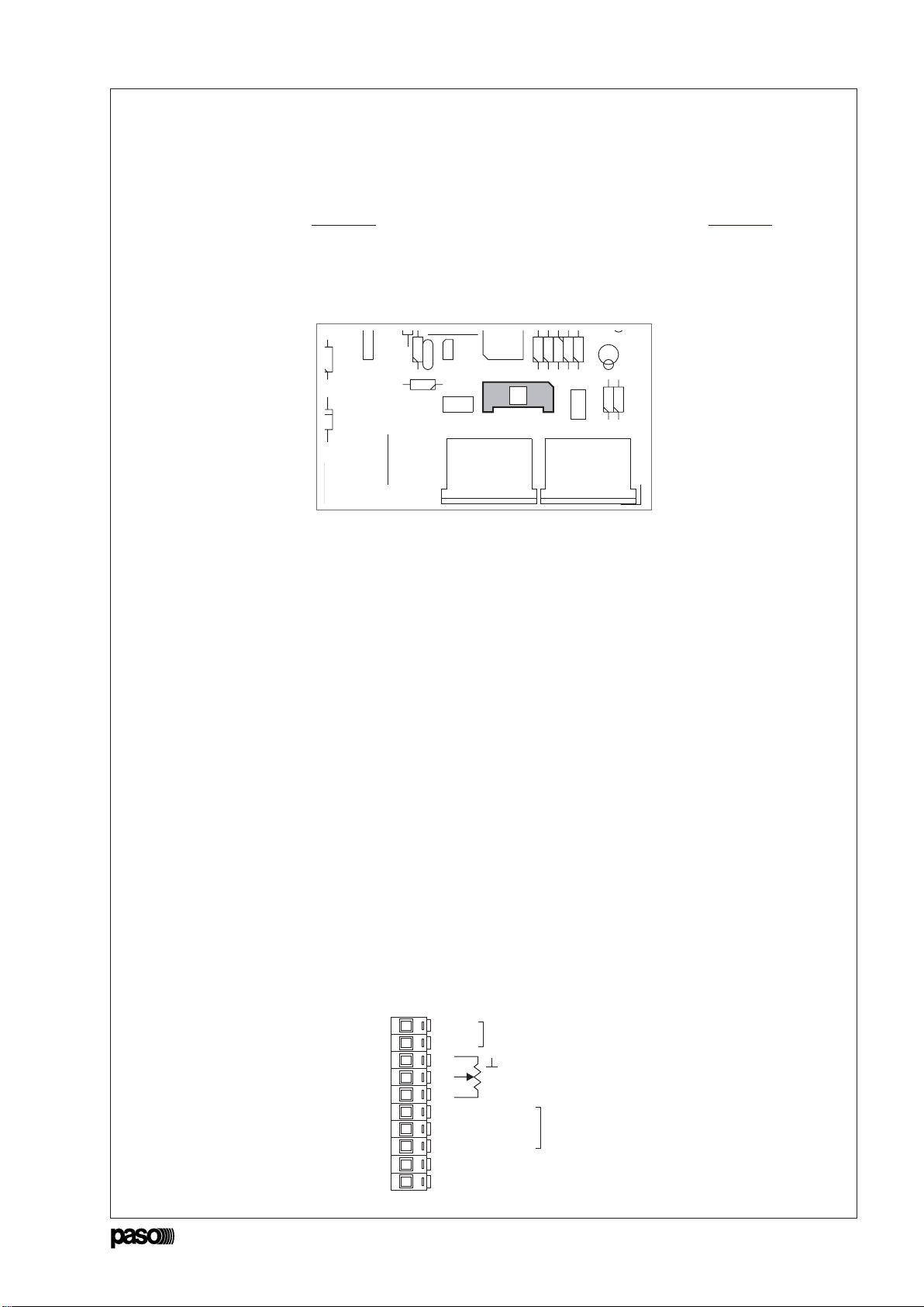
• Connettore ‘REMOTE CONTROL’
Questo connettore deve essere utilizzato per il collegamento
dell’amplificatore ad un personal computer.
3.5.2 Modalità di funzionamento
Le modalità di funzionamento consentite dalla scheda sono due:
• Modalità ‘STAND-ALONE’;
• Modalità ‘CONTROLLO REMOTO’
Nei paragrafi seguenti verranno illustrate tutte le impostazioni e
le modifiche che possono essere applicate alla scheda in entrambe
le modalità d’uso.
A)Modalità ‘STAND-ALONE’
In questa modalità, è necessario impostare alcuni parametri
tramite l'apposito dip-switch ‘MODE SEL.’ presente sul
posteriore dell'amplificatore.
NOTA
La levetta 1del dip-switch svolge la funzione di ‘Invio’: deve
essere cioè utilizzata per dare conferma delle scelte effettuate
con le altre leve.
Pin Descrizione
1alimentazione esterna 24V (opzionale)
2alimentazione esterna 24V (opzionale)
3massa
4selezione ingressi
5RS485 +
6alimentazione esterna 24V (opzionale)
7massa
8massa
9RS485 –
Una volta effettuata questa connessione,
sarà possibile controllare tramite software
dedicato la scheda PM2092-V.
Nella tabella sottostante è riportata la
piedinatura del connettore.
• Acquisizione dell'impianto
Una volta installata in modo definitivo la linea di altoparlanti
e collegato l'amplificatore come indicato nel capitolo
‘Connessioni’, è necessario che l'amplificatore acquisisca
l'impedenza corrente. Tale impedenza verrà presa come
riferimento per le misurazioni future.
Qualora le misure superino il ± 20% della misura di
riferimento, l'amplificatore segnalerà tramite led l'anomalia
rilevata. Per acquisire l'impedenza di riferimento, procedere nel
seguente modo:
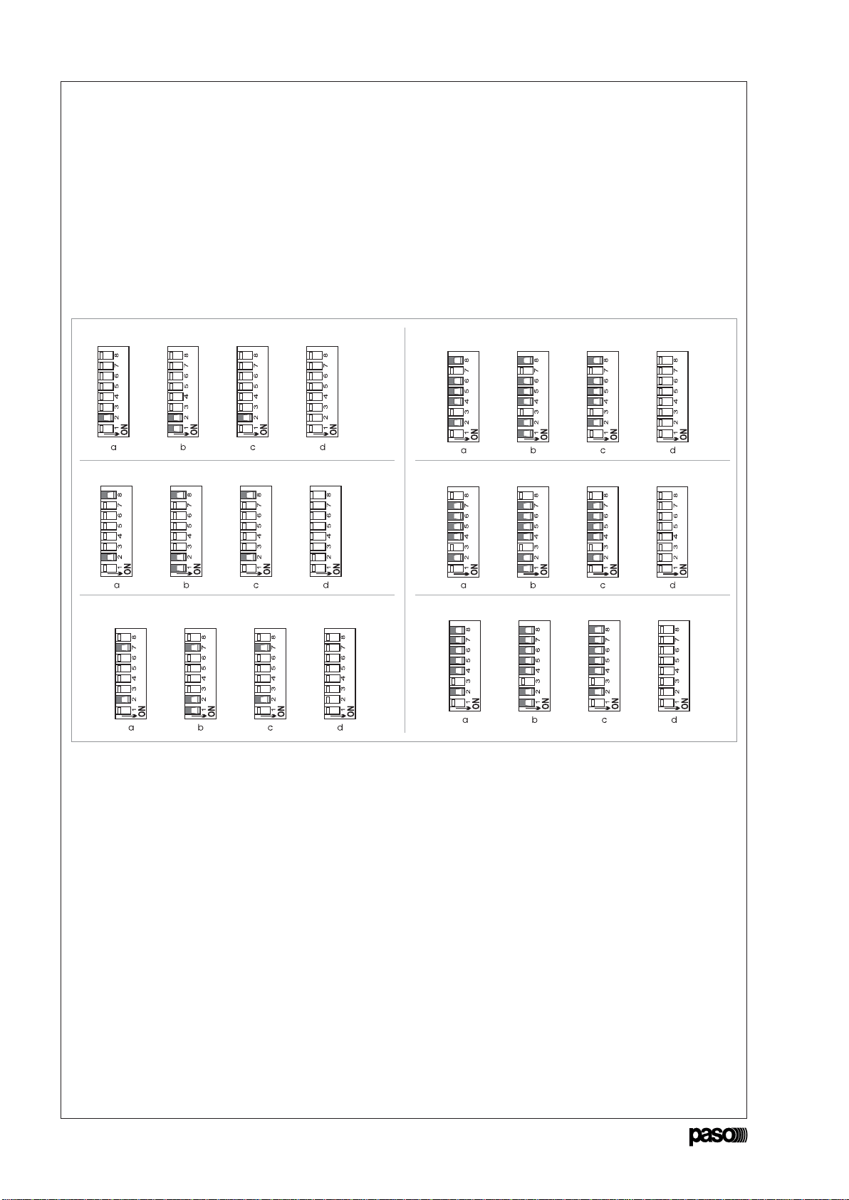
1. Accendere l'amplificatore.
2. Operare sul dip-switch portando in posizione ON la levetta 8 e
successivamente la levetta 1 come indicato in figura 3.5.7.
Il led verde ‘OK’ lampeggierà due volte e dopo alcuni secondi
rimarrà acceso in modo fisso ad indicare la corretta acquisizione
della linea.
3. Riportare la leva 1 e la leva 8 in posizione OFF: il led verde si
spegne.
Fig. 3.5.6
Fig. 3.5.7
• ‘REMOTE CONTROL’ Connector
This connector has to be used to connect the amplifier to a
personal computer.
Once this connection has been made, it will
then be possible to control the PM2092-V
card by means of dedicated software.
The following table shows the pinout of the
connector.
Pin Description
124V external power supply (optional)
224V external power supply (optional)
3GND
4inputs selection
5RS485 +
624V external power supply (optional)
7GND
8GND
9RS485 –
3.5.2 Operating modes
There are two possible operating modes enabled by the card:
• ‘STAND-ALONE’ mode;
• ‘REMOTE CONTROL’ mode.
The settings and the changes that can be applied to the card in
each of the operating modes are described in the following
paragraphs.
A)‘STAND-ALONE’ mode
In this mode, it is necessary to set some parameters using the
‘MODE SEL.’ dip-switch provided for this purpose on the rear
of the amplifier.
NOTE
Lever 1 of the dip-switch has an ‘Enter’ function. That is to say,
it has to be used to confirm the choices opted for with the other
levers.
• Acquisition of the system
Once the loudspeaker line has been permanently installed, and
the amplifier has been connected as indicated in the chapter
on ‘Connections’, it is necessary for the amplifier to acquire the
current impedance. This impedance value will be used as a
reference for the future measurements. If the results of the
measurements exceed the reference value by ± 20%, the
amplifier will signal the problem that has been detected by
means of the LED. To acquire the reference impedance value,
proceed as follows:
1. Switch on the amplifier.
2. Operate the dip-switch by moving lever 8 to the ON position
and then lever 1 as shown in Figure 3.5.7.
The green ‘OK’ LED will then flash twice, and after a few seconds
it will remain on steadily to indicate that the line has been
correctly acquired.
3. Return lever 1 and lever 8 to their OFF positions.
The green LED will extinguish.
4. GEBRUIK VAN HET APPARAAT
4.1 Inschakeling
Alvorens het apparaat in werking te stellen, dient u zich ervan te
verzekeren dat u alle voor het systeem benodigde aansluitingen
tot stand heeft gebracht. Zet de netschakelaar [4] op de stand
ON. Het controlelampje ‘ON’ [2] geeft aan dat het apparaat is
ingeschakeld.
4.2 Display
Met uitzondering van de led die aangeeft dat het apparaat is
ingeschakeld [2], kunnen de led’s [3] op het frontpaneel het
uitgangsniveau en/of de functietoestand van de versterker
aangeven (zie par. ‘Display met led’s. pagina 40).
5. OPMERKINGEN
5.1 Geforceerde ventilatie
De versterkers PMW500-V zijn uitgerust met een ventilator
voor de geforceerde koeling van de laatste vermogenstrappen
en van het binnenste van het apparaat. Deze ventilator, die
beschikt over een eigen voedings- en besturingscircuit, treedt
automatisch in werking bij het bereiken van een bepaalde
temperatuur van de warmtewisselaar en schakelt uit wanneer
de temperatuur weer op een normale waarde komt. In de praktijk
is bij standaard gebruikscondities van dit soort versterkers, dat
wil zeggen de verspreiding van achtergrondmuziek afgewisseld
met gesproken mededelingen op vol vermogen, en bij normale
klimatologische omstandigheden, geforceerde ventilatie niet nodig
en wordt deze dan ook niet ingeschakeld; dit leidt tot een
aanzienlijke reductie van de mechanische slijtage van de
bewegende delen, een vermindering van de hoeveelheid stof
die door de ventilator in het apparaat wordt gevoerd en, niet op
de laatste plaats, een vermindering van het omgevingslawaai
veroorzaakt door het grote aantal draaiende ventilatoren in het
geval van systemen met één of meer kasten met een grote
hoeveelheid boosters. De ventilator zuigt frisse lucht aan door
de openingen op de achterzijde van het apparaat [9] en voert
de verwarmde lucht af via de openingen op de voorzijde [1];
het is dan ook van het grootste belang dat deze openingen
nooit geblokkeerd worden.
5.2 Overbelasting en beveiligingen
De PMW500-V zijn niet alleen uitgerust met de traditionele
beveiliging door middel van zekeringen, maar beschikken ook over
een elektronische beveiliging en een thermische beveiliging die
het apparaat beschermen tegen het risico van eventuele
beschadigingen. Toepassing van een lagere belastingsimpedantie
dan de nominale waarde betekent dat aan het apparaat
voortdurend een hoger vermogen wordt gevraagd dan het op kan
brengen. Hierdoor kunnen de eindvermogenstrappen en de
uitgangstransformator beschadigd raken. Om dergelijke problemen
te voorkomen, zijn de versterkers van het modulaire systeem
uitgerust met een beveiligingscircuit tegen overbelasting met
automatische reset. Het beveiligingscircuit zal onmiddellijk in
werking treden indien zich één van de volgende situaties voordoet:
- kortsluiting op één van de uitgangen voor luidsprekers.
-belastingsimpedantie lager dan 50% van de nominale waarde.
-vermogen dat gevraagd wordt door het systeem van
luidsprekers, aangesloten op de constante spanningslijnen,
hoger dan het vermogen dat de versterker kan leveren.
De overbelastingsconditie wordt aangegeven door dat het
controlelampje ‘OVD’ [3] op het frontpaneel van het apparaat
gaat knipperen. Het apparaat zal de normale werking hervatten
zo gauw men de oorzaak van de overbelasting heeft
weggenomen. De thermische beveiliging, die eveneens over een
automatische reset beschikt, treedt in werking in het geval het
apparaat een te hoge temperatuur bereikt, bijvoorbeeld als gevolg
van een te hoge omgevingstemperatuur of een onvoldoende
ventilatie van de kast. Wanneer de thermische beveiliging
geactiveerd wordt, stopt de versterker met werken, alle led's
gaan uit en alleen de ventilator blijft in werking.
4. USO DEL APARATO
4.1 ENCENDIDO
Antes de encender el aparato es preciso comprobar que todas
las conexiones necesarias para completar la instalación hayan
sido realizadas correctamente. Poner el interruptor de red [4]
en la posición ON. El piloto luminoso ‘ON’ [2] confirma el
encendido del aparato.
4.2 Display
Los LEDs [3] del panel frontal, salvo el correspondiente al
encendido del aparato [2], pueden actuar como indicadores
del nivel de salida y/o como indicadores del estado de
funcionamiento del amplificador (ver apartado ‘Display de LEDs,
página 40).
5. NOTAS DE SERVICIO
5.1 Ventilación forzada
Los amplificadores PMW500-V disponen de un ventilador para
enfriar de manera forzada las etapas finales de potencia y el
interior del aparato.
Este ventilador, con su proprio circuito de alimentación y
control, se activa automáticamente cuando se alcanza una
determinada temperatura en el disipador de calor y se detiene
cuando la temperatura vuelve a niveles normales.
Prácticamente, en condiciones de uso normales para
amplificadores de este calibre, como la difusión de música
ambiente con intercalados anuncios vocales a plena potencia,
y en condiciones climáticas normales, la ventilación forzada
no es necesaria por lo que no es activada; esto conlleva una
reducción notable del desgaste mecánico de las partes en
movimiento, la reducción de la acumulación de polvo
introducida en el aparato por los ventiladores y también la
reducción del ruido ambiente causado por el alto número de
ventiladores en movimiento en el caso de instalaciones con
uno o más armarios que contengan un gran número de booster.
El ventilador aspira aire fresco por las ranuras traseras del
aparato [9] y expulsa el aire caliente por las ranuras delanteras
[1], por lo tanto es preciso no tapar nunca dichas ranuras.
5.2 Condiciones de sobrecarga y protecciones
El PMW500-V dispone, además que de la protección clásica
proporcionada por los fusibles, de una protección electrónica y
de una térmica que los protegen contra eventuales riesgos de
daños. Aplicar un valor de impedancia de carga inferior a la
nominal significa pedir al aparato una potencia superior a la
proporcionable con continuidad.
Esto puede llevar a dañar las etapas finales de potencia y el
transformador de salida.
Para no correr estos riesgos los amplificadores del sistema
modular disponen de circuito de protección contra las
sobrecargas con restablecimiento automático. El circuito de
protección interviene inmediatamente sobre el amplificador en
el caso de que se produzca uno de los casos siguientes:
- cortocircuito en una de las salidas para altavoces.
- impedancia de carga inferior al 50% del valor nominal.
- potencia requerida por el sistema de difusores, conectados
en las líneas de tensión constante, superior a la
suministrable por el amplificador.
La condición de sobrecarga queda señalada por el encendido,
intermitente, del piloto luminoso ‘OVD’ [3] situado en el panel
frontal del aparato. El aparato vuelve a funcionar normalmente
tan pronto se haya procedido a eliminar la causa de la sobrecarga.
La protección térmica, también ella del tipo con autoresta-
blecimiento, interviene cuando el aparato alcanza una
temperatura excesiva debida, por ejemplo, a una temperatura
ambiente demasiado alta o a una escasa ventilación del armario
rack. Durante la intervención de la protección térmica el
amplificador cesa de funcionar, todos los LED se apagan y queda
en función sólo el ventilador.
44 9