Transition Networks TN-EOT Series User manual

Transition Networks TN-EOT-xx User Guide
33720 Rev. C https://www.transition.com Page 1 of 13
TN-EOT-xx
Ethernet over Two-wire Extender SFPs
User Guide
•Enable the Ethernet over 2-wire on our MC/Switch by plugging in the Ethernet Extender SFP
•Compliant with any Gigabit SFP slot
•Based on VDSL2 technology
•Utilize the existing 2-wire cable
•Support maximum data rate up to 300Mbps per line
•Distance up to 3000 meters
•-40 to +75°C extended operating temperature
Contents
Description..................................................................................................................................................................1
Order Information........................................................................................................................................................2
Specifications..............................................................................................................................................................2
Interface Pin Assignments (RJ-45) .........................................................................................................................3
Data Rates - UTP....................................................................................................................................................3
Data Rates - Coax...................................................................................................................................................4
Application Example ...................................................................................................................................................4
Package Contents ......................................................................................................................................................5
Install Overview ..........................................................................................................................................................5
Ethernet over Coax .................................................................................................................................................5
Ethernet over 2 Wire with Adapter ..........................................................................................................................5
Ethernet over 2 Wire without Adapter .....................................................................................................................6
Verified Host Devices..................................................................................................................................................6
Install Procedure.........................................................................................................................................................7
LED Descriptions ........................................................................................................................................................8
Troubleshooting ..........................................................................................................................................................9
Record System and Device Information .................................................................................................................. 10
Service, Warranty, and Tech Support .......................................................................................................................11
Contact Us ........................................................................................................................................................... 12
Regulatory Agency Information ............................................................................................................................... 12
Declaration of Conformity .................................................................................................................................... 12
Record of Revisions................................................................................................................................................. 13
Description
The Transition Networks TN-EOT-xx is an integrated Small-Form Factor Pluggable (SFP) module that enables
traditional Ethernet switch, media converter and other network appliances to connect beyond typical Ethernet
coverage (100 meters). Incorporated with the latest VDSL2 technology, this SFP can be easily adapted to existing
applications with existing 2-wire cable, such as phone line, to avoid the cost of rewiring. It can drastically extend
the Ethernet service on UTP wire with distance up to 3000 meters, and even with the rate of 100Mbps speed up
to 400 meters on a standard Cat 5e 2-wire cable.
The SFP also supports Telco grade noise cancellation techniques like Interleave, high SNR profile, and
retransmission that can effectively eliminate the noise impact to ensure your service/control messages can
securely deliver in a harsh environment.
With long reach coverage, high noise immunity, and compact board size, the Transition Networks TN-EOT-xx is
an ideal upgrade for your Enterprise or Industry applications.

Transition Networks TN-EOT-xx User Guide
33720 Rev. C https://www.transition.com Page 2 of 13
Order Information
The TN-EOT-CO and the TN-EOT-RT are sold separately and are used in pairs.
Model
Interface
TN-EOT-CO
SFP, Ethernet Extender, Server, 1000Base-X, RJ-45 (includes RJ to BNC and RJ to
Terminal Block adapters).
SFP Compliant; CO side Ethernet Extender SFP; 300Mbps (Aggregate rate).
TN-EOT-RT
SFP, Ethernet Extender, CPE, 1000Base-X, RJ-45 (includes RJ to BNC and RJ to
Terminal Block adapters).
SFP Compliant; CPE side Ethernet Extender SFP; 300Mbps (Aggregate rate).
TN-EOT-CO Extender SFP TN-EOT-RT Extender SFP
RJ-45 to BNC (Pigtail) Adapter, 28008 RJ-45 to Terminal Block Adapter, 28009
Specifications
Standards
IEEE 802.3z, ITU-T VDSL2
Connectors
One RJ-45
Software
MTU: Max. 2048 bytes
MAC Address: 00-C0-F2-7A-00-00 through 00-C0-F2-7A-CE-1F
Self Boot & Managed by Internal Flash when plugged into an unmanaged device
Status LEDs
LED1: ORANGE: On: Server; Off: CPE
LED2: GREEN: Link Status
Dimensions
Width: 0.52” [13 mm] x Depth: 3.1” [79 mm] x Height: 0.67” [17 mm]
Power Input
3.3v, 700mA
Environment
Operating Temperature: -40 ~ +75°C.
Storage Temperature: -40 ~ +85°C
Operating Humidity: 10% to 90% (non-condensed)
Storage Humidity: 5% to 95% (non-condensed)
Weight
0.07 lbs. [.03 kg]
ESD Class
2kV
Compliance
Safety; CE / FCC
Warranty
1 year

Transition Networks TN-EOT-xx User Guide
33720 Rev. C https://www.transition.com Page 3 of 13
Interface Pin Assignments (RJ-45)
The interface is a standard eight-pin modular jack.
The table below shows the pin out assignments.
Pin #
Description
1
Not Used
2
Not Used
3
Not Used
4
Analog Input
5
Analog Input
6
Not Used
7
Not Used
8
Not Used
Data Rates - UTP
Data transfer rates are shown in the table below.
Cable (2-wire Cat 5)
CO to RT (Mbps)
RT to CO (Mbps)
Bi-dir. (Mbps)
260 feet
160
160
320 (160/160)
1000 feet
111
111
222 (111/111)
1260 feet
89
89
178 (89/89)
Data transfer measurements were made on Transition Networks M/GE-ISW-SFP-01 media converters. Frame
size used = 2048 bytes.

Transition Networks TN-EOT-xx User Guide
33720 Rev. C https://www.transition.com Page 4 of 13
Data Rates - Coax
Data transfer rates are shown in the table below.
Coax Cable
CO to RT (Mbps)
RT to CO (Mbps)
Bi-dir. (Mbps)
260 feet
160
160
320 (160/160)
1000 feet
111
111
222 (111/111)
1260 feet
89
89
178 (89/89)
Data transfer measurements were made on Transition Networks M/GE-ISW-SFP-01 media converters. Frame
size used = 2048 bytes.
Application Example
TN-EOT-xx SFPs are typically used with Transition Networks’ M/GE-ISW-SFP-01.
Recommended for use with media converters and unmanaged switches.
Does not support use of “Link Pass Thru”. The media converter’s Link Pass Through
(LPT) feature does not work. Supports a maximum MTU of 2048.
Typically for use with unmanaged devices; lock up issues may occur when used with
managed devices.
When the TN-EOT-xx SFP is installed in managed switches, the SFPs maintain synchronization during port state
changes (Disable/Enable). During resets and power cycles, the SFPs maintain sync if the ports were specifically
configured for 1Gbps speed rather than Auto. With some switches, the S3290 in particular, this configuration must
be performed before you insert the SFP.
The TN-EOT-xx SFP doesn’t support SGMII; the port is set to 1Gbps speed by default.

Transition Networks TN-EOT-xx User Guide
33720 Rev. C https://www.transition.com Page 5 of 13
Package Contents
Verify you have received the following items. Contact your
sales representative if any of these items is missing or damaged.
Save the packaging for possible future use.
□One TN-EOT-CO or one TN-EOT-RT SFP
□One RJ-45 to BNC (Pigtail) Adapter, 28008
□One RJ-45 to Terminal Block Adapter, 28009
□One Printed Quick Install Guide
Install Overview
The TN-EOT-xx is an Ethernet Extender in a standard SFP form factor; it provides the ability to leverage the
existing 2-Wire or Coax cable infrastructure to extend the Ethernet service. The TN-EOT-xx can quickly enable
any switch or media converter with a Gigabit SFP slot to connect beyond typical Ethernet distances (100 meters).
Ethernet over Coax
The TN-EOT-xx can extend the Ethernet service on Coax up to 500 meters at 120Mbps bi-directional data rate
(60Mbps downstream and upstream).
Use the RJ-45 to BNC (Pigtail) Adapter, 28008 on both ends for Ethernet over Coax:
Ethernet over 2 Wire with Adapter
The TN-EOT-xx can extend the Ethernet service on 2-wire with distances up to 400 meters at 200Mbps
bi-directional data rate or extend Ethernet on non-UTP 26AWG with distances up to 500 meters at 120Mbps
bi-directional data rate.
Use the RJ-45 to Terminal Block Adapter, 28009 on both ends for Ethernet over 2 Wire:

Transition Networks TN-EOT-xx User Guide
33720 Rev. C https://www.transition.com Page 6 of 13
Ethernet over 2 Wire without Adapter
The TN-EOT-xx can extend the Ethernet service on 2-wire with distances up to 400 meters at 200Mbps
bi-directional data rate or extend Ethernet on non-UTP 26AWG with distances up to 500 meters at 120Mbps
bi-directional data rate.
Connect the twisted pair directly to the SFP through the RJ-45 connector (not using the adapters):
Verified Host Devices
The TN-EOT-xx is verified with the host devices below:
•MGE-ISW-SFP-01
•S3290
•S4224
•SM8TAT2SA
•ION C6120-1040
Note that the TN-EOT-xx can’t work with TN industrial switches in full temperature range (especially in high temp).

Transition Networks TN-EOT-xx User Guide
33720 Rev. C https://www.transition.com Page 7 of 13
Install Procedure
When the TN-EOT-xx SFP is installed in managed switches, the SFPs maintain synchronization during port state
changes (Disable/Enable). During resets and power cycles, the SFPs maintain sync only if the ports were
specifically configured for 1Gbps speed rather than Auto. With some switches, the S3290 in particular, this
configuration must be performed before you insert the SFP.
The TN-EOT-xx doesn’t work on 100Base SFP slot or in SGMII Auto mode; if used with a managed switch, set
speed of SFP slots to Gigabit.
Use the provided adapters as follows:
□Use the RJ-45 to BNC (Pigtail) Adapter, 28008 on both ends for Ethernet over Coax.
□Use the RJ-45 to Terminal Block Adapter, 28009 on both ends for Ethernet over 2 Wire.
1. Insert a TN-EOT-RT into the host device. LED1 lights (orange) as an indicator of RT. Check for physical
connection: LED 2 begins flashing green slowly as soon as you insert the TN-EOT-RT.
2. Insert an Adapter into the TN-EOT-RT. Connect the cabling.
3. Insert a TN-EOT-CO into the host device. Check for physical connection: LED2 (green) begins flashing Green
slowly as soon as you insert the TN-EOT-CO.
4. Insert an Adapter into the TN-EOT-CO. Connect the cabling.
5. Link time takes about 60 seconds. Fast flashing Green LED2 indicates DSL training. LED2 on both SFPs (TN-
EOT-CO and TN-EOT-RT) stays Green when devices link up.

Transition Networks TN-EOT-xx User Guide
33720 Rev. C https://www.transition.com Page 8 of 13
LED Descriptions
The TN-EOT-xx SFP LEDs are shown and described below.
LED 1 (Orange): CO/RT Indicator LED 2 (Green): DSL Link Status Indicator
LED
Color
State
Description
LED 1
Orange
Off
On
CO side
RT side
LED 2
Green
Off
Blinking
On
No DSL connection
DSL trying to train
DSL link is on

Transition Networks TN-EOT-xx User Guide
33720 Rev. C https://www.transition.com Page 9 of 13
Troubleshooting
Use the steps below to isolate the problem to the TN-EOT-xx and correct the problem.
1. Verify the operating environment matches the specs; see the Specifications section on page 2 above.
2. Check the LEDs; see the Install Procedure on page 5 above.
3. Make sure your application is supported; see Application Example on page 4 above.
4. Make sure the power source meets specs and is operating correctly.
5. For problems with large frames (greater than 4098 bytes) causing the link to drop, try setting the max MTU to
2048 bytes in the application.
6. Make sure the CO side connections and devices are good.
7. Make sure the CPE side connections and devices are good.
8. Record system and device information (see below) before contacting TN Technical Support:
9. Contact Transition Networks Technical Support. See Contact Us on page 12 below.
See the device and package labels for recording troubleshooting information.
TN-EOT-CO SFP Extender
TN-EOT-RT SFP Extender
TN-EOT-xx SFP Package Label

Transition Networks TN-EOT-xx User Guide
33720 Rev. C https://www.transition.com Page 10 of 13
Record System and Device Information
After performing the troubleshooting procedures, and before calling or emailing Technical Support, please record
as much information as possible in order to help the TN Technical Support Specialist.
1. Record the Model Information for your system. See Package and Device Labeling below.
2. Model # TN-EOT-CO SN: _____________________ Model # TN-EOT-RT SN: ________________________
3. Provide additional product information to your Technical Support Specialist.
Your Transition Networks service contract number: _____________________________________________
Describe the failure: ______________________________________________________________________
_______________________________________________________________________________________
Describe any action(s) already taken to resolve the problem (e.g., change switch mode, reboot, etc.):
_______________________________________________________________________________________
_______________________________________________________________________________________
The model # of other Transition Networks product in the network: ___________________________________
_______________________________________________________________________________________
_______________________________________________________________________________________
4. Describe your network environment (devices, layout, cable type, etc.): ______________________________
_______________________________________________________________________________________
_______________________________________________________________________________________
_______________________________________________________________________________________
Network load and frame size at the time of trouble (if known): _____________________________________
The device history (i.e., have you returned the device before, is this a recurring problem, etc.):
_______________________________________________________________________________________
_______________________________________________________________________________________
5. Any previous Return Material Authorization (RMA) numbers: ______________________________________
_______________________________________________________________________________________

Transition Networks TN-EOT-xx User Guide
33720 Rev. C https://www.transition.com Page 11 of 13
Service, Warranty, and Tech Support
Transition Networks warrants to the original consumer or purchaser that this product and all components thereof will be
free from defects in material and/or workmanship for a period of one year from the original factory shipment date. Any
warranty hereunder is extended to the original consumer or purchaser and is not assignable. Transition Networks makes no
express or implied warranties including, but not limited to, any implied warranty of merchantability or fitness for a
particular purpose, except as expressly set forth in this warranty. In no event shall Transition Networks be liable for
incidental or consequential damages, costs, or expenses arising out of or in connection with the performance of the
product delivered hereunder. Transition Networks will in no case cover damages arising out of the product being used in a
negligent fashion or manner.
This warranty does not cover damage from accident, acts of God, neglect, contamination, misuse or abnormal conditions of
operation or handling, including over-voltage failures caused by use outside of the product’s specified rating, or normal
wear and tear of mechanical components.
Transition Networks will, at its option:
•Repair the defective product to functional specification at no charge
•Replace the product with an equivalent functional product
•Refund a portion of purchase price based on a depreciated value
To return a defective product for warranty coverage, contact Transition Networks’ Customer Support for a return
authorization number.
Send the defective product postage and insurance prepaid to the following address:
Transition Networks, Inc.
10900 Red Circle Drive
Minnetonka, MN 55343
USA
Attn: RETURNS DEPT: CRA/RMA # ___________
Failure to properly protect the product during shipping may void this warranty. The return authorization number must be
written on the outside of the carton to ensure its acceptance. We cannot accept delivery of any equipment that is sent to us
without a CRA or RMA number.
CRA’s are valid for 60 days from the date of issuance. An invoice will be generated for payment on any unit(s) not returned
within 60 days.
Upon completion of a demo/ evaluation test period, units must be returned or purchased within 30 days. An invoice will be
generated for payment on any unit(s) not returned within 30 days after the demo/ evaluation period has expired.
The customer must pay for the non-compliant product(s) return transportation costs to Transition Networks for evaluation
of said product(s) for repair or replacement. Transition Networks will pay for the shipping of the repaired or replaced in-
warranty product(s) back to the customer (any and all customs charges, tariffs, or/and taxes are the customer’s
responsibility).
Before making any non-warranty repair, Transition Networks requires a $200.00 charge plus actual shipping costs to and
from the customer. If the repair is greater than $200.00, an estimate is issued to the customer for authorization of repair. If
no authorization is obtained, or the product is deemed not repairable, Transition Networks will retain the $200.00 service
charge and return the product to the customer not repaired. Non-warranted products that are repaired by Transition
Networks for a fee will carry a 180-day limited warranty. All warranty claims are subject to the restrictions and conventions
set forth by this document.
Transition Networks reserves the right to charge a $50 fee for all testing and shipping incurred, if after testing, a return is
classified as “No Problem Found.”
THIS WARRANTY IS YOUR ONLY REMEDY. NO OTHER WARRANTIES, SUCH AS FITNESS FOR A PARTICULAR PURPOSE, ARE
EXPRESSED OR IMPLIED. TRANSITION NETWORKS IS NOT LIABLE FOR ANY SPECIAL, INDIRECT, INCIDENTAL OR
CONSEQUENTIAL DAMAGES OR LOSSES, INCLUDING LOSS OF DATA, ARISING FROM ANY CAUSE OR THEORY. AUTHORIZED
RESELLERS ARE NOT AUTHORIZED TO EXTEND ANY DIFFERENT WARRANTY ON TRANSITION NETWORKS’S BEHALF.

Transition Networks TN-EOT-xx User Guide
33720 Rev. C https://www.transition.com Page 12 of 13
Contact Us
Call us at 800-526-9267 or +1-952-941-7600. Telephone: +1-952-941-7600. Toll Free: 800-526-9267
Fax: 952-941-2322 Web: https://www.transition.com
Address: 10900 Red Circle Drive, Minnetonka, MN 55343 USA
Regulatory Agency Information
Declaration of Conformity
Standards CE / FCC
FCC Regulations
NOTE: This equipment has been tested and found to comply with the limits for a Class A digital device, pursuant to Part
15 of the FCC Rules. These limits are designed to provide reasonable protection against harmful interference when the
equipment is operated in a commercial environment. This equipment generates, uses, and can radiate radio frequency energy
and, if not installed and used in accordance with the instruction manual, may cause harmful interference to radio
communications. Operation of this equipment in a residential area is likely to cause harmful interference in which case the user
will be required to correct the interference at his own expense.
CE Marking
This is a Class A product. In a domestic environment, this product could cause radio interference; as a result, the customer
may be required to take adequate preventative measures.

Transition Networks TN-EOT-xx User Guide
33720 Rev. C https://www.transition.com Page 13 of 13
European Regulations
WARNING: This is a Class A product. In a domestic environment, this product could cause radio interference in which case
the user may be required to take adequate measures.
Achtung ! Dieses ist ein Gerät der Funkstörgrenzwertklasse A. In Wohnbereichen können bei Betrieb dieses Gerätes
Rundfunkstörungen auftreten. In diesem Fäll ist der Benutzer für Gegenmaßnahmen verantwortlich.
Attention ! Ceci est un produit de Classe A. Dans un environment domestique, ce produit risque de créer des interférences
radioélectriques, il appartiendra alors à l’utilsateur de prende les measures spécifiques appropriées.
In accordance with European Union Directive 2002/96/EC of the European Parliament and of the Council of 27
January 2003, Transition Networks will accept post usage returns of this product for proper disposal. The contact
information for this activity can be found in the ‘Contact Us’ portion of this document.
CAUTION: RJ connectors are NOT INTENDED FOR CONNECTION TO THE PUBLIC TELEPHONE NETWORK. Failure to
observe this caution could result in damage to the public telephone network.
Der Anschluss dieses Gerätes an ein öffentlickes Telekommunikationsnetz in den EG-Mitgliedstaaten verstösst gegen die
jeweligen einzelstaatlichen Gesetze zur Anwendung der Richtlinie 91/263/EWG zur Angleichung der Rechtsvorschriften der
Mitgliedstaaten über Telekommunikationsendeinrichtungen einschliesslich der gegenseitigen Anerkennung ihrer Konformität.
Record of Revisions
Rev
Date
Description
A
6/20/17
Initial release.
B
8/8/17
Add coax data rates.
C
6/11/21
Remove MSA compliant reference, change “Hardened -40 to +75°C operating
temperature” to “-40 to +75°C extended operating temperature”, and list verified host
devices.
This manual suits for next models
2
Table of contents
Other Transition Networks Extender manuals

Transition Networks
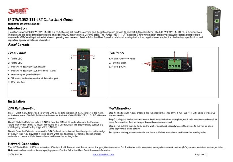
Transition Networks IPOTW1052-111-LRT User manual

Transition Networks
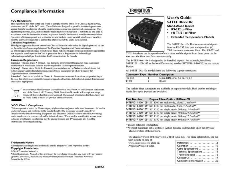
Transition Networks S4TEF10xx-10x User manual

Transition Networks
Transition Networks CCSCF3011-110 User manual

Transition Networks
Transition Networks EO2PSE4052-111 User manual

Transition Networks
Transition Networks EO2P 4052-111 Series User manual

Transition Networks
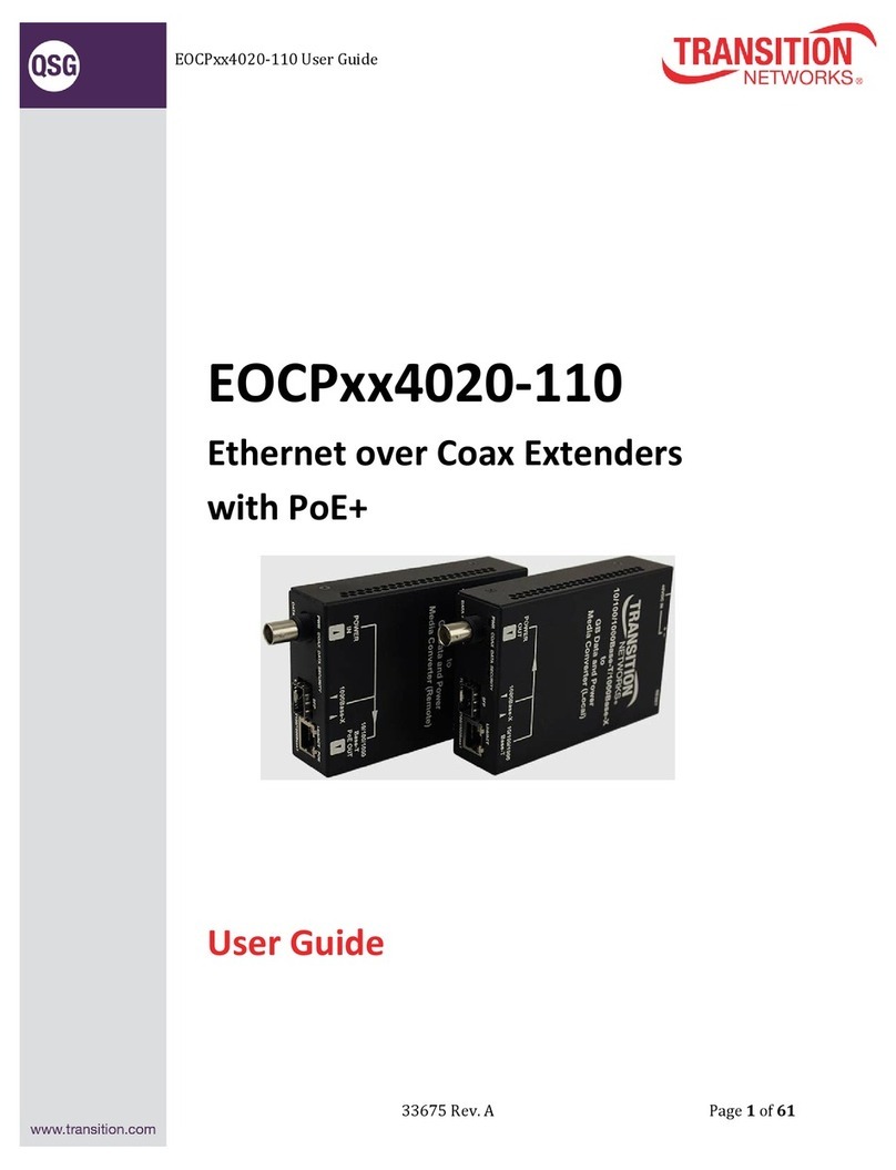
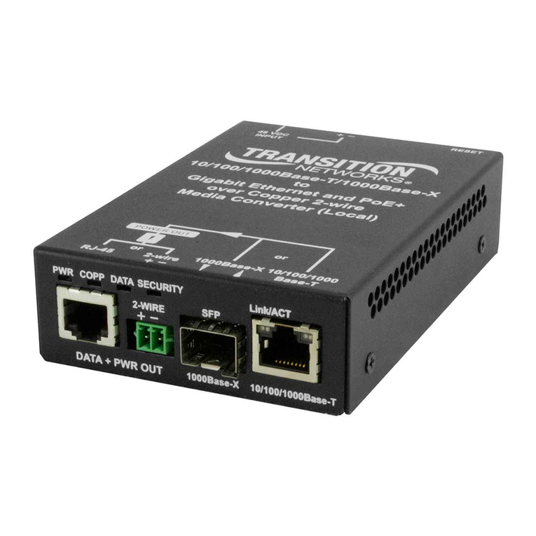
Transition Networks EOCPxx4020-110 User manual

Transition Networks
Transition Networks EO2Pxx4052-111 User manual

Transition Networks
Transition Networks EOCP 4020-110 Series User manual

Transition Networks
Transition Networks EOCPxx4020-110 User manual