HP 517 User manual

HP 517 Unified Walljack Installation Guide
Abstract
This document describes the procedure to install and initially configure the HP 517 Unified Walljack (HP 517). It is intended
for professional installers who are trained in RF installation and knowledgeable in local regulations including building and
wiring codes, safety, channel, power, indoor/outdoor restrictions, and license requirements for the country of use.
HP Part Number: 5998-4524
Published: May 2014
Edition: 1

© Copyright 2014 Hewlett-Packard Development Company, L.P.
The information contained herein is subject to change without notice. The only warranties for HP products and services are set forth in the express
warranty statements accompanying such products and services. Nothing herein should be construed as constituting an additional warranty. HP shall
not be liable for technical or editorial errors or omissions contained herein.
Acknowledgments
Microsoft® is a U.S. registered trademark of Microsoft Corporation.
Warranty
WARRANTY STATEMENT: To obtain a copy of the warranty for this product, see the warranty information website:
http://www.hp.com/support/Networking-warranties

Contents
1 Getting started...........................................................................................4
Overview................................................................................................................................4
Ports.......................................................................................................................................4
Radio and antennas..................................................................................................................5
Reset button.............................................................................................................................5
2 Installing the HP 517...................................................................................6
Planning the installation site.......................................................................................................6
Remove product from packaging.................................................................................................7
Installing on an electrical box.....................................................................................................7
Installing on a wall...................................................................................................................8
Installing on a desktop..............................................................................................................9
Initial configuration.................................................................................................................10
3 LEDs.......................................................................................................12
4 Support and other resources......................................................................14
Contacting HP........................................................................................................................14
Related information.................................................................................................................14
Websites..........................................................................................................................14
Typographic conventions.........................................................................................................14
5 Documentation feedback...........................................................................16
A Regulatory information..............................................................................17
Turkey RoHS material content declaration...................................................................................17
Ukraine RoHS material content declaration................................................................................17
Warranty information..............................................................................................................17
Contents 3

1 Getting started
The HP 517 Unified Walljack is a single-radio dual-band 3x3:3 802.11ac walljack that can
support up to 50 wireless clients.
In its factory default state, the HP 517 can be provisioned through its web-based management tool
using Microsoft Internet Explorer 8 or later, or Mozilla Firefox 17 or later.
NOTE: When operating, the HP 517 is warm to the touch. When operating at room temperature,
the face of the unit can be as high as 40°C (104°F). This is expected.
Overview
Figure 1 (page 4) shows multiple views of an HP 517.
Figure 1 HP 517
Side and bottom viewsBack viewFront view
7. Pass Through port4. Pass Through port1. Status LEDs
nl
Power, Uplink, Radio 8. Power adapter socket5. PoE Uplink port
9. Ethernet LAN ports 1–36. Console port2. LAN port status LEDs
10. PoE PSE Ethernet LAN port 43. PoE PSE/port 4 LED
Ports
The following ports are located on the HP 517:
•Four Gigabit Ethernet ports: Auto-sensing 1000 BASE-T Ethernet ports with RJ-45 connectors.
Port 4 supports IEEE 802.3af Power over Ethernet (PoE) to supply power to one device. Located
at the bottom of the unit.
•A Gigabit Ethernet uplink port: Auto-sensing 1000 BASE-T Ethernet port with RJ-45 connector.
Located at the back of the unit.
•Two (in and out) pass-through ports: Cat5e-compatible ports with RJ-45 connectors. Located
on the back and side of the unit.
•Console port: Reserved for HP-directed debugging. Located at the back of the unit.
4 Getting started

PoE PSE port power
No power out PSE port 4802.3af powered
Class 2 power via PSE port 41
802.3at powered
Class 2 or 3 power via PSE port 4Local DC powered
1Because up to 11 watts can be supplied, the software supports a class 3 override option.
Radio and antennas
The HP 517 provides a single IEEE 802.11a/b/g/n/ac radio for 802.11ac very-high throughput
(VHT) applications and IEEE 802.11a/b/g/n for legacy support applications.
There are three antennas supporting 3x3 MIMO spatial streams for up to 1.3 Gbps PHY rates.
The HP 517 supports 802.11b/g/n operation modes at 2.4 GHz or 802.11a/n/ac operation
modes at 5 GHz.
NOTE: The HP 517 does not support concurrent operation at 2.4 GHz and 5 GHz.
Reset button
The reset button is accessible through a hole on the side panel of the HP 517.
Radio and antennas 5

2 Installing the HP 517
The HP 517 is designed to be mounted on a standard NEMA-WD6 (US) or BS 4662 (International)
electrical outlet box.
If you use the optional HP Unified Wired-WLAN Walljack Table/Flush Wall Mount Kit (JL022A),
the HP 517 can be mounted on a desktop or wall.
The end user is responsible for ensuring that installation and use comply with local safety and radio
regulations.
IMPORTANT: This device requires professional installation. Consult a professional installer trained
in RF installation and knowledgeable in local regulations including:
•Building and wiring codes
•Safety regulations
•Channel, power, and indoor/outdoor restrictions
•License requirements for the intended country
Planning the installation site
Determine an appropriate location to mount the unit. Use the following guidelines to select the
installation site.
CAUTION: To ensure adequate ventilation when installed on an electrical box or wall, the
ventilation slots must not be blocked in any way. Ensure that there is at least 15.25 cm (6 inches)
of clearance from all vents.
Be sure to install the unit in an area that is well ventilated and maintains an ambient temperature
of less than 40°C (104°F). If the installation area has any obstructions to air flow, you must take
steps to ensure adequate airflow is maintained. Do not install in enclosed spaces, at ground level,
or close to or directly above any heat sources or heat-emitting devices, such as:
•Radiators
•Portable room heaters
•The back of refrigerators or compressors
•Direct sunlight
•Transformers
•Power pack units of halogen or similar lighting fixtures or appliances
CAUTION: To avoid signal interference, do not install the HP 517 near or behind known RF
absorbers, reflectors, and interference sources. Examples of sources that degrade RF performance
include:
•Cement and brick
•Objects that contain water
•Metal
•Microwave ovens
•Wireless phones and headsets
•Mirrors
6 Installing the HP 517

Remove product from packaging
Inspect the package contents and verify that they are free from defects. The package contains:
•HP 517 Unified Walljack
•Mounting bracket
•Ethernet jumper cable
•Screws
•Documentation
Installing on an electrical box
Before you begin, run the required network cables through the bottom of the electrical outlet box
on which you are installing the HP 517. Be sure to provide enough cable length to reach the HP
517.
NOTE: The HP 517 is shipped with two pairs of mounting screws. The two shorter mounting
screws are for a standard NEMA-WD6 (US) electrical box. The two longer mounting screws are
for a BS 4662 (worldwide) electrical outlet box.
1. Place the mounting bracket, with the UP arrow pointing up, on the electrical outlet box, and
then use two mounting screws to secure the bracket to the box.
3. Screws1. Electrical box
4. Bracket screw2. Mounting bracket
2. Connect the network cable from the box to the RJ-45 Uplink port on the back of the HP 517.
If required, also connect the cable providing support for pass-through devices to the Pass
Through port on the back of the HP 517.
3. Push the HP 517 onto the mounting bracket on the box, then slide it down until it is fully
engaged. Do not let go of the HP 517 until you confirm that it is securely in place.
4. Use the supplied small Phillips head bracket screw to secure the side of the HP 517 to the
bracket.
5. Connect cables:
•Connect equipment that requires PoE to Port 4.
•Connect other equipment to Ports 1, 2, 3, and 4.
•Connect equipment that will use the pass-through feature (such as a digital telephone) to
the Pass Through port on the side of the HP 517.
Remove product from packaging 7

Installing on a wall
When installing the HP 517 on a wall, ensure that the surface to which you attach the HP 517
and the fasteners you use can support at least 0.9 kg (2 lbs). Allow extra weight for cables.
1. Hold the optional Unified Wired WLAN Walljack Table/Flush Wall Mount panel in a vertical
orientation against the wall where it will be installed. Mark two holes for the screws or
user-supplied wall anchors.
2. If using wall anchors, drill two holes, typically 4.7 mm (3/16 inch) in diameter, and then
insert the anchors and tap them flush with the wall.
3. Use the supplied two screws to loosely attach the mount panel to the wall.
4. Run the required network cables through the top, bottom, or sides of the wall mount panel
allowing sufficient length for the cables to reach the not-yet installed HP 517.
5. Tighten the screws to secure the mount panel to the wall.
6. Place the mounting bracket, with the UP arrow pointing up, on the wall mount panel, and then
use four mounting screws to secure the bracket to the panel.
8 Installing the HP 517

7. Connect the network cable from the panel to the RJ-45 Uplink port on the back of the HP 517.
If required, also connect the cable providing support for pass-through devices to the Pass
Through port on the back of the HP 517.
8. Push the HP 517 onto the mounting bracket on the box, then slide it down until it is fully
engaged. Do not let go of the HP 517 until you confirm that it is securely in place.
9. Use the supplied small Phillips head bracket screw or Torx-10 security screw to secure the side
of the HP 517 to the bracket.
10. Connect cables:
•Connect equipment that requires PoE to Port 4.
•Connect other equipment to Ports 1, 2, 3, and 4.
•Connect equipment that will use the pass-through feature (such as a digital telephone) to
the Pass Through port on the side of the HP 517.
Installing on a desktop
CAUTION: Be sure to install the units in an area that is well ventilated and maintains an ambient
temperature of less than 40°C (104°F). Do not install in enclosed spaces or close to or directly
above any heat sources or heat-emitting devices. If the installation area has any obstructions to air
flow, you must take steps to ensure adequate airflow is maintained. The ventilation slots must not
be blocked in any way. Ensure that there is at least 15.25 cm (6 inches) of clearance from all
vents.
1. Hold the optional Unified Wired WLAN Walljack Table/Flush Wall Mount panel on the
desktop where it will be installed. Mark two holes for the screws.
2. Use the supplied two screws to loosely attach the mount panel to the table.
3. Run the required network cables through the top, bottom, or sides of the mount panel allowing
sufficient length for the cables to reach the not-yet installed HP 517.
4. Tighten the screws to secure the mount panel to the table.
5. Place the mounting bracket, on the mount panel, and then use four mounting screws to secure
the bracket to the panel.
Installing on a desktop 9

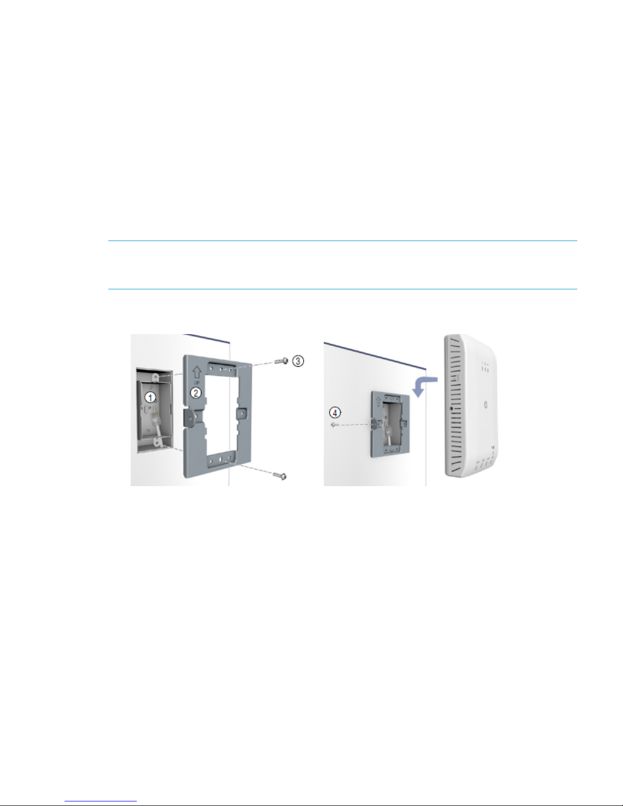
6. Connect the network cable from the panel to the RJ-45 Uplink port on the back of the HP 517.
If required, also connect the cable providing support for pass-through devices to the Pass
Through port on the back of the HP 517.
7. Push the HP 517 onto the mounting bracket, then slide it down until it is fully engaged. Do
not let go of the HP 517 until you confirm that it is securely in place.
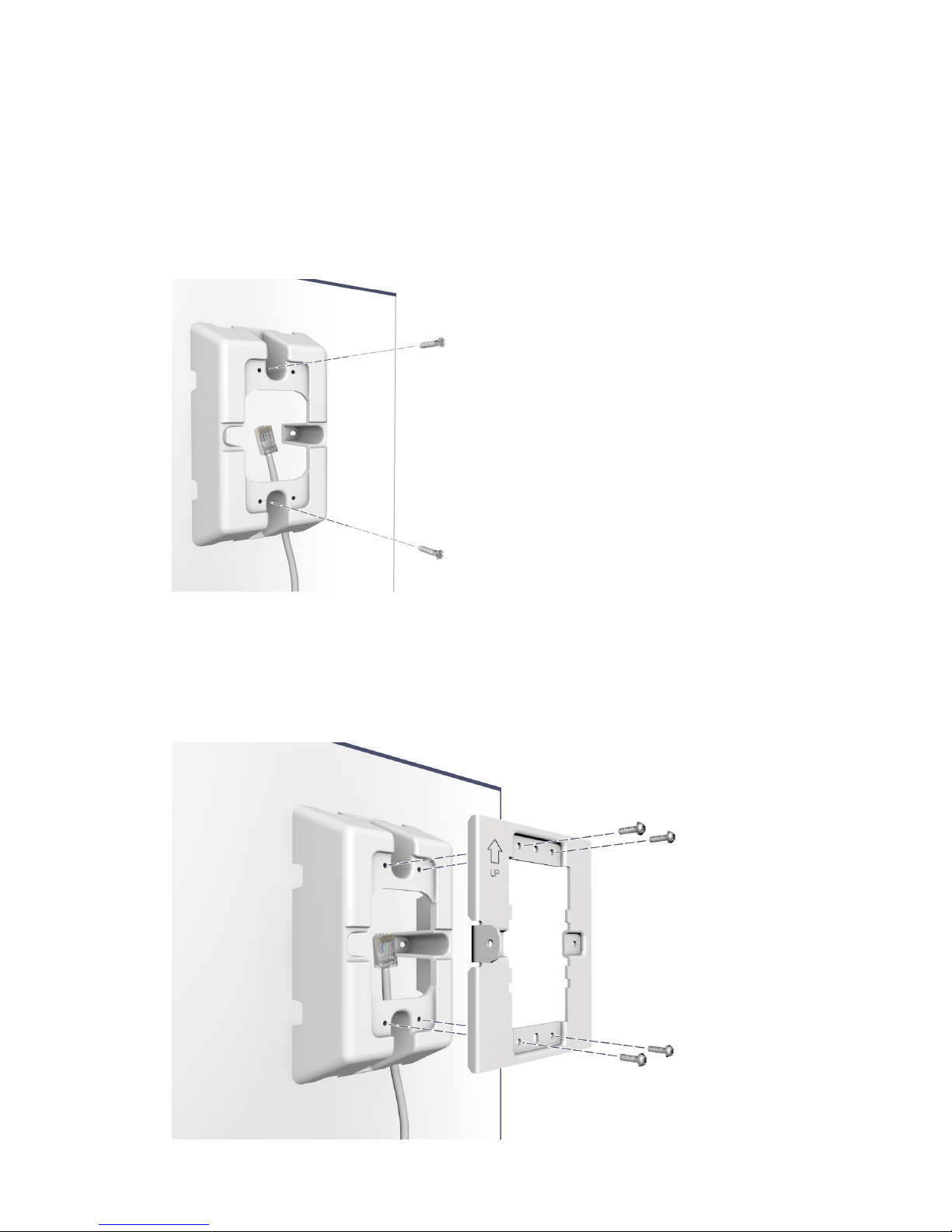
8. Use the supplied small Phillips head bracket screw or Torx-10 security screw to secure the side
of the HP 517 to the bracket.
9. Connect cables:
•Connect equipment that requires PoE to Port 4.
•Connect other equipment to Ports 1, 2, 3, and 4.
•Connect equipment that will use the pass-through feature (such as a digital telephone) to
the Pass Through port on the side of the HP 517.
Initial configuration
When the Uplink port is connected and the HP 517 is powered on, the device is designed to
automatically discover and associate with an HP MSM wireless controller in the connected network.
In its factory default state, the HP 517 can be provisioned through its web-based management tool
using Microsoft Internet Explorer 8 or later, or Mozilla Firefox 17 or later.
NOTE: Direct configuration of the HP 517 is only possible when the HP 517 is in its factory-default
state, meaning that it has not been provisioned or has not discovered an HP MSM wireless controller
since last being reset to factory defaults. To force the HP 517 into its factory-default state, insert a
paper clip into the reset button hole, and press and hold the reset button until the status LEDs flash
three times, then release.
The following procedure describes how to perform initial configuration for a factory-default HP
517. For instructions on how to perform other configuration procedures, see the HP 517 802.11ac
Unified Walljack Configuration Guide.
NOTE: Do not power on the HP 517 until directed.
1. Configure your computer:
a. Disconnect your computer LAN port and configure it to use a static IP address in the range
192.168.1.2 to 192.168.1.254, and a subnet mask of 255.255.255.0. Set the default
gateway to 192.168.1.1, and DNS server to 192.168.1.1.
b. Disable any wireless connection on your computer.
10 Installing the HP 517

2. Connect the cables and power on the HP 517.
IMPORTANT: When using the PoE PSE Ethernet LAN port 4 to power a 802.3af powered
device (PD), the cable length from LAN port 4 to the PD must be no more than 3 m.
a. Connect the cables:
•If using a PoE switch, use an Ethernet cable to connect an unused factory-default PoE
switch port to the HP 517 Uplink port.
•If using a PoE injector, use Ethernet cables to connect a network switch to the data-in
port of the PoE injector and the HP 517 Uplink port to the data and power-out port
of the PoE injector.
If connecting a PoE injector to a port on a PoE capable switch, be sure to disable
the power output on the PoE switch.
•If using an AC/DC adapter, connect it to the power connector on the HP 517.
b. Power on the HP 517 by powering on the PoE switch, power injector, or by plugging in
the AC/DC adapter.
Initially, the HP 517 power LED is amber. Wait approximately one minute until it turns
green before proceeding to the next step.
c. Connect the LAN port on your computer to the uplink port, directly or through a switch.
For detailed information on how to configure and manage the HP 517, see “Working with controlled
APs” in the HP 517 802.11ac Unified Walljack Configuration Guide.
NOTE: When operating, the HP 517 is warm to the touch. This is expected.
Initial configuration 11

3 LEDs
Table 1 Startup behavior
DescriptionRadio LEDUplink LEDPower LED
The HP 517 has no power.OffOffOff
Power is applied.
If the power LED remains amber for several minutes, the software has failed to
load. If this occurs, reset or power cycle the HP 517. If this condition persists,
contact HP support.
——Amber
Flashing every two seconds: The HP 517 is starting up.
Flashing every second: The HP 517 is looking for an IP address or building the
list of VLANs on which to support discovery.
——
Flashing
green
The HP 517 has obtained an IP address and is attempting to discover a
controller.
Flashing green in sequence
The HP 517 is attempting to establish a management tunnel with a controller.Alternately flashing
green
Green
The HP 517 has received a discovery reply form two or more controllers with
the same priority setting.
Off
Alternately flashing
green (quickly)
The HP 517 is attempting to establish an Ethernet connection to the uplink port.
Off
Alternately flashing
green (slowly)
Table 2 Controlled behavior
DescriptionStateLED
The HP 517 has power applied.Amber
Power The HP 517 is associated with a wireless controller and is fully operational.Green
The port is not connected or there is no activity.Off
Uplink
Network activity on a valid 10/100 Mbps link.Flashing
amber
Network activity on a valid 1000 Mbps link.Flashing
green
Either the radio is disabled or there is no network activity.Off
Radio
Wireless network activity in 2.4 GHz mode.Flashing
amber
Wireless network activity in 5 GHz mode.Flashing
green
The port is not connected or there is no activity.Off
LAN
nl
(1 to 4)
Network activity on a valid 10/100 Mbps link.Flashing
amber
Network activity on a valid 1000 Mbps link.Flashing
green
No PoE device is connected.Off
PoE Class 1 or 2 power is being supplied to the device attached to port 4.Amber
A fault condition while a Class 1 or 2 PoE device is configured on port 4.Flashing
amber
12 LEDs

Table 2 Controlled behavior (continued)
DescriptionStateLED
Class 3 power is being supplied to the device attached to port 4.Green
A fault condition while a Class 3 PoE device is configured on port 4.Flashing
green
13

4 Support and other resources
Contacting HP
For worldwide technical support information, see the HP support website:
http://www.hp.com/support
Before contacting HP, collect the following information:
•Product model names and numbers
•Technical support registration number (if applicable)
•Product serial numbers
•Error messages
•Operating system type and revision level
•Detailed questions
Related information
The following documents provide related information:
•HP 517 802.11ac Unified Walljack Configuration Guide
•HP 517 802.11ac Unified Walljack Quickstart
You can find these documents on the Manuals page of the HP Support Center website:
http://www.hp.com/support/manuals
Enter your product name or number, and click GO.
Websites
•HP Technical Support website: http://www.hp.com/support
•HP Networking Support website: www.hp.com/networking/
Typographic conventions
Table 3 Document conventions
ElementConvention
Cross-reference linksBlue text: Table 3 (page 14)
Website addressesBlue, underlined text: http://www.hp.com
Bold text •Keys that are pressed
•Text typed into a GUI element, such as a box
•GUI elements that are clicked or selected, such as menu
and list items, buttons, tabs, and check boxes
Text emphasisItalic text
14 Support and other resources

Table 3 Document conventions (continued)
ElementConvention
Monospace text •File and directory names
•System output
•Code
•Commands, their arguments, and argument values
Monospace, italic text •Code variables
•Command variables
Emphasized monospace textMonospace, bold text
WARNING! Indicates that failure to follow directions could result in bodily harm or death.
CAUTION: Indicates that failure to follow directions could result in damage to equipment or data.
IMPORTANT: Provides clarifying information or specific instructions.
NOTE: Provides additional information.
Typographic conventions 15

5 Documentation feedback
HP is committed to providing documentation that meets your needs. To help us improve the
documentation, send any errors, suggestions, or comments to Documentation Feedback
([email protected]). Include the document title and part number, version number, or the URL
when submitting your feedback.
16 Documentation feedback

A Regulatory information
For important safety, environmental, and regulatory information, see Safety and Compliance
Information for Server, Storage, Power, Networking, and Rack Products, available at http://
www.hp.com/support/Safety-Compliance-EnterpriseProducts.
Turkey RoHS material content declaration
Türkiye Cumhuriyeti: EEE Yönetmeliğine Uygundur
Ukraine RoHS material content declaration
Обладнання відповідає вимогам Технічного регламенту щодо обмеження використання деяких
небезпечних речовин в електричному та електронному обладнанні, затвердженого постановою
Кабінету Міністрів України від 3 грудня 2008 № 1057
Warranty information
HP Networking Products
http://www.hp.com/support/Networking-Warranties
Turkey RoHS material content declaration 17
Table of contents
Other HP Network Card manuals

HP
HP StorageWorks FC1142SR User instructions

HP
HP 10BT NightDIRECTOR/100 User manual

HP
HP 289166-40B User manual

HP
HP Memory Modules User manual

HP
HP AB290A User manual

HP
HP Ethernet USB Network Adapter hn210e User manual

HP
HP External Devices User manual

HP
HP A7011A User manual

HP
HP PN1050 User manual

HP
HP Console Management Controller User manual
Popular Network Card manuals by other brands

National Instruments
National Instruments NI MATRIXx Xmath Specification sheet

Askey
Askey WLF3020 user guide

D-Link
D-Link 32-bit PCI Fast Ethernet Network Adapter... manual

ICP DAS USA
ICP DAS USA ZT-2026 quick start

Delta Electronics
Delta Electronics Ethernet Communication Module IFD9507 instruction manual

Toshiba
Toshiba USB001Z instruction manual