TransLite TL-9242A User manual

P a g e | 1
DISCLAIMER
No part of this document may be reproduced in any form without the written permission of the copyright
owner.
The contents of this document are subject to revision without notice due to continued progress in
methodology, design and manufacturing. TRANSLITE GLOBAL LLC shall have no liability for any error or
damage of any kind resulting from the use of this document.
COPY WARNING
This document includes some confidential information. Its usage is limited to the owners of the
product that it is relevant to. It cannot be copied, modified, or translated in another language
without prior written authorization from TRANSLITE GLOBAL LLC
PRODUCT MODEL NUMBER: TL-9242A 4-in-1
MPEG-2/H.264 HD Encoder
ABOUT THIS MANUAL

P a g e | 2
INDEX
TABLE OF CONTENTS
CHAPTER 1 INTRODUCTION ...................................................................................................................3
1.1 PRODUCT OVERVIEW........................................................................................................................3
1.2 KEY FEATURES...................................................................................................................................3
1.3 SPECIFICATIONS...............................................................................................................................4
1.4 PRINCIPLE CHART.............................................................................................................................5
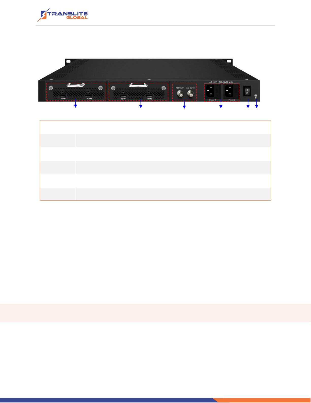
1.5 APPEARANCE AND DESCRIPTION......................................................................................................6
CHAPTER 2 INSTALLATION GUIDE...........................................................................................................7
2.1 GENERAL PRECAUTIONS ...................................................................................................................7
2.2 POWER PRECAUTIONS......................................................................................................................8
2.3 DEVICE’S INSTALLATION FLOW CHART ILLUSTRATED AS FOLLOWING..................................................8
2.4 ENVIRONMENT REQUIREMENT.........................................................................................................8
2.5 GROUNDING REQUIREMENT.............................................................................................................9
CHAPTER 3 OPERATION..........................................................................................................................9
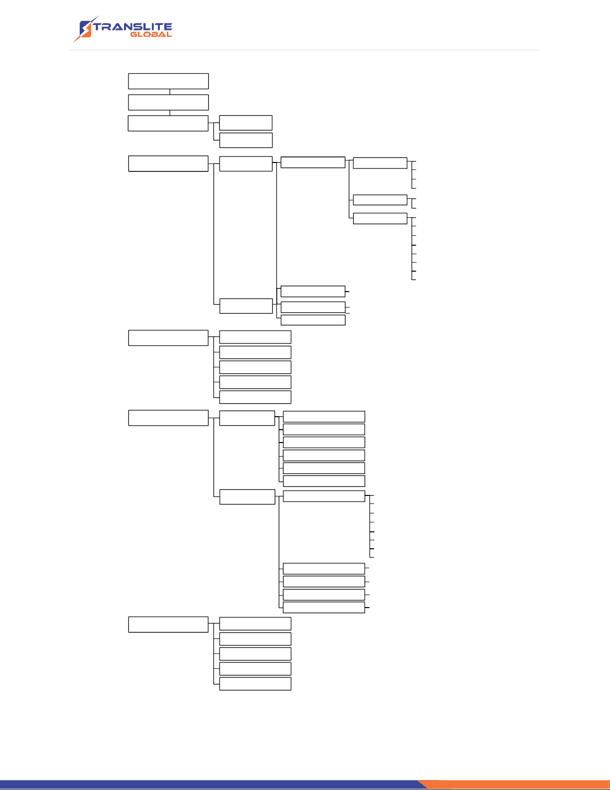
3.1 LCD MENU STRUCTURE.....................................................................................................................9
3.2 GENERAL SETTINGS FOR MAIN MENU ............................................................................................. 11
CHAPTER 4 WEB NMS OPERATION.......................................................................................................21
4.1 LOGIN ............................................................................................................................................21
4.2 OPERATION .................................................................................................................................... 22
CHAPTER 5 TROUBLESHOOTING........................................................................................................... 29
CHAPTER 6 PACKING LIST..................................................................................................................... 30

P a g e | 3
CHAPTER 1
INTRODUCTION
1.1 PRODUCT OVERVIEW
TL-9242A is our new professional HD audio & video encoding device with powerful
functionality. It has equipped with 4 HDMI channels input supporting MPEG-2 and MPEG-4
AVC/H.264 video encoding and MPEG-1 Audio layer 2, LC-AAC, HE-AAC and AC3 audio
encoding. The 4 encoded HDMI programs will output through ASI and IP ports in MPTS or
SPTS.
It adopts inner drawer-type structural design which greatly facilitates the change of
encoding modules if needed.
We apply dual power supplies with one for backup to provide a better protection for your
business.
1.2 KEY FEATURES
➢Dual power supply
➢MPEG2 HD/SD & MPEG4 AVC/H.264 HD/SD video encoding
➢MPEG1 Audio Layer 2, LC-AAC, HE-AAC and AC3 audio encoding
➢4*HDMI input
➢Support VBR/CBR rate control mode
➢Support Low Latency function
➢Support PSI/SI editing and inserting
➢Supports IP null packet filter
➢ASI output, IP (MPTS & 4 SPTS) output over UDP, RTP
➢LCD display, Remote control and firmware
➢Web-based NMS management; Updates via web

P a g e | 4
1.3 SPECIFICATIONS
Video
Encoding
MPEG2 & MPEG4 AVC/H.264
Input
HD-SDI*4 or HDMI*4
Resolution
1920*1080_60P, 1920*1080_50P, (-for MPEG4 AVC/H.264 only)
1920*1080_60i, 1920*1080_50i,
1280*720_60p, 1280*720_50P
720*480_60i, 720*576_50i
Bit Rate
0.5~19.5Mbps
Rate Control Mode
CBR/VBR
Audio
Encoding
MPEG1 Layer II, MPEG2-AAC, MPEG4-AAC, Dolby Digital AC3 (2.0)
Sample rate
48KHz
Bit rate
64kbps, 96kbps,128kbps, 192kbps, 256kbps, 320kbps
System
Local interface
LCD + control buttons
Remote
management
Web NMS
Low Latency Mode
Normal, mode 1, mode 2
Output
2*ASI out (BNC type);
IP (1 MPTS & 4 SPTS) over UDP, RTP (RJ45, 100M)
NMS interface
RJ45, 100M
Language
English

P a g e | 5
General
Power
AC 100V~240V, 45W
Dimensions
482*400*44mm
Weight
4.5 kgs
Operation
temperature
0~45℃
1.4 PRINCIPLE CHART

P a g e | 6
1.5 APPEARANCE AND DESCRIPTION
Front Panel Illustration
1 2 3 4 5 6 7 8
1
LCD window
2
Power supply indicators
3
Power Alarm Switch: When only one power supply is connected or one of
the power supplies fails, the device will give alarm sound, and then press the
alarm switch to turn off the alarm sound.
4
NMS port for the connection between the device and PC
5
DATA port for IP signal out
6
Indicators for whole unit power supply, working alarm and input signal lock
status
7
Control Buttons
8
Handles

P a g e | 7
Rear Panel Illustration
1 2 3 4 5 6
1
HDMI Input Module 1: Program input port 1&2
2
HDMI Input Module 2: Program input port 3&4
3
ASI output ports
4
Power Supply Slot
5
Power Switch
6
Grounding
CHAPTER 2
INSTALLATION GUIDE
This section is to explain the cautions the users must know in some case that possibly injure
may bring to users when it’s used or installed. For this reason, please read all details here and
make in mind before installing or using the product.
2.1 GENERAL PRECAUTIONS
➢Must be operated and maintained free of dust or dirty.
➢The cover should be securely fastened, do not open the cover of the products
when the power is on.
➢After use, securely stow away all loose cables, external antenna, and others.

P a g e | 8
2.2 POWER PRECAUTIONS
➢When you connect the power source, make sure if it may cause overload.
➢Avoid operating on a wet floor in the open. Make sure the extension cable is in
good condition
➢Make sure the power switch is off before you start to install the device
2.3 DEVICE’S INSTALLATION FLOW CHART
ILLUSTRATED AS FOLLOWING
Connecting
Grouding
Wire and
Power
Cord
Acquisition
Check Installing
Device Setting
Parameter Running
Device
Connecting
Signal
cable
2.4 ENVIRONMENT REQUIREMENT
Item
Requirement
Machine Hall
Space
When user installs machine frame array in one machine hall, the distance
between 2 rows of machine frames should be 1.2~1.5m and the distance
against wall should be no less than 0.8m.
Machine Hall
Floor
Electric Isolation, Dust Free
Volume resistivity of ground anti-static material: 1X10⁷~1X10¹⁰,
Grounding current limiting resistance: 1M(Floor bearing should be
greater than 450Kg/㎡)
Environment
Temperature
5~40℃(sustainable),0~45℃(short time)
installing air-conditioning is recommended
Relative
Humidity
20%~80% sustainable 10%~90% short time
Pressure
86~105KPa

P a g e | 9
Door &
Window
Installing rubber strip for sealing door-gaps and dual level glasses for
window
Wall
It can be covered with wallpaper, or brightness less paint.
Fire
Protection
Fire alarm system and extinguisher
Power
Requiring device power, air-conditioning power and lighting power are
independent toeach other. Devicepower requiresAC 110V±10%, 50/60Hz
or AC 220V±10%, 50/60Hz. Please carefully check before running.
2.5 GROUNDING REQUIREMENT
➢All function modules’ good grounding is the basis of reliability and stability of devices. Also,
they are the most important guarantee of lightning arresting and interference rejection.
Therefore, the system must follow this rule.
➢Grounding conductor must adopt copper conductor in order to reduce high frequency
impedance, and the grounding wire must be as thick and short as possible.
➢Users shouldmake sure the 2 ends of grounding wire well electric conducted and be antirust.
➢It is prohibited to use any other device as part of grounding electric circuit
➢The area of the conduction between grounding wire and device’s frame should be no less
than 25mm2.
CHAPTER 3
OPERATION
3.1 LCD MENU STRUCTURE
Please refer to the diagram below

P a g e | 10
Initializing
General Working Status
1 Status
2 Input Sets
3.1 TSID
3.2 ONID
3.3 Output Bitrate
3.4 NIT Insert
3.5 ASI Output
Low Delay
2.1 Input 1
2.2 Input 2
Video Format
Video Bitrate
Audio Format
Audio Bitrate
2.1.1 Program 1
(Same content with 2.1.1)
2.1.2 Program 2
2.2.1 Program 1
2.2.2 Program 2
(Same content with 2.1.1)
3 TS Config
1.1 Alarm
1.2 Uptime
Video
Audio
Program Info
Video in status
Service name
Program name
Program number
PCR PID
Video PID
Program output
PMT PID
Audio PID
4 Network 4.1 NMS
4.2 IP Stream
4.1.1 NMS IP
4.1.2 Subnet mask
4.1.3 Gateway
4.1.4 MAC Address
4.1.5 Web NMS Port
4.1.6 Reset Password
4.2.1 MPTS Output
4.2.2 SPTS A
4.2.3 SPTS B
4.2.4 SPTS C
4.2.5 SPTS D
Output IP
Null PKT Filter
Output Port
Subnet Mask
Gateway
Data Enable
Service IP
Protocol
(Same content with 4.2.1)
5.1 Save Config
5.2 Load Saved
5.3 Factory Reset
5.4 LCD time-out
5.5 Version
5 System

P a g e | 11
Initial Status
After powering on the device,it will take a few seconds to initialize the system It shows as
below:
➢TL-9242A HD Encoder: Module number and name
➢P1: Program 1; P2: Program 2; P3: Program 3; P4: Program 4
➢X.XX Mbps: indicate the current encoding bit rate of the corresponding channel.
3.2 GENERAL SETTINGS FOR MAIN MENU
By pressing “Lock”key on the front panel, user can enter the main menu. The LCD will display
the following pages:
User can press UP/DOWN buttons to specify menu item, and then press ENTER to enter the
submenus as below:
1) Status
Press Enter to enter “Status”and it displays the working time duration of the device. It times
upon power
Start up…
Start OK…
1 Status
2 Input Sets
3 TS Config
4 Network
5 Network
TL-9242A HD Encoder
P1:X.XXMbps P2: X.XXMbps
1.1 Alarm
1.2 Uptime

P a g e | 12
➢Alarm
The alarm indicator will turn on if there is no A/V signals inputting or outputting bit rate
overflows. User then can enter this menu to check the error type.
➢Uptime
It displays the working time duration of the device. It times upon power on.
2) Input Sets
Under this submenu, the LCD will show “2.1 Input 1”and “2.2 Input 2”to represent the two
HDMI input modules respectively.
Each HDMI input module support two program input connecters. Under submenus 2.1 (or 2.2),
user could set the video/audio parameters for the 2 HDMI programs respectively.
Uptime
0 Day(s) xx-xx-xx
2.1 Input 1
2.2 Input 2
2.1.1 Program 1
2.1.2 Program 2
Video
Video in status
Video Format
Low Delay
Audio
Audio Format
Audio Bit rate

P a g e | 13
➢Video in Status
Users can enter this menu to check the video input status.
➢Video Format
The HDMI encoding module supports both “MPEG2”and “H.264”video encoding formats.
Users can enter this menu to select one format from the 2 options.
Press ENTER to shift ‘*’to ‘►’, and then press UP/DOWN buttons to specify one item and then
press ENTER to confirm. Press MENU to step back to upper-level menu. (The operation
method is applicable for rest part.)
MPEG2
H.264
Program Info
Program output
Program name
Service name
Program number
PMT PID
PCR PID
Video PID
Audio PID

P a g e | 14
➢Low Delay
This unit can achieve a low time delay from encoding to decoding terminal end-to-end.
…..………………………………..... NOTE ……..……..………………………….
The different combination of Video Format, Video Bit-rate, Low Delay Mode, the Resolution of
signal source and Decoding solution adopted on terminal side will have an impact on the
latency.
…………………………………………………………………………………………..……
➢Video Bit Rate
Users can set the video encoding bit rate manually in this menu.
0.5~19.5Mbps for H.264 encoding
1~19.5Mbps for MPEG-2 encoding
➢Audio Format
The HDMI encoding module supports 4 encoding formats. Users can enter this menu to select
one format from the 4 options.
Normal
Mode 1
Video Bit Rate
14.000 Mbps
MPEG1 Layer 2
MPEG2 AAC
MPEG4 AAC
AC3
Mode 2

P a g e | 15
➢Audio Bit Rate
The audio bit rate ranges from 64Kbps to 320Kbps. Users can select one bit-rate from the
options provided.
➢Program Info
Users can enable or disable the program output in the first sub-menu and configure the other
parameters in the rest sub-menus.
Audio Bitrate
64Kbps
Program Output
Enable
Program Name
TV-101
Service Name
TV-Provider
Program number
0x101
PMT PID
0x101
PCR PID
0x100
Video PID
0x100
Audio PID
0x100

P a g e | 16
3) TS Config
This encoder support TS output via ASI ports. ‘TS Config’is for the configuration of ASI output.
Its submenus contain:
➢TS ID/ON ID
Users can set the TS ID and Original Network ID in the 2 submenus. The IDs are in
hexadecimal form.
➢Output Bit rate
Users can set the max output bit rate for the ASI MPTS out. (Range 0-100 Mbps)
3.1 TS ID
3.2 ON ID
3.3 Output Bit rate
3.4 NIT Insert
3.5 ASI Output
TS ID
0x0001
ON ID
0x0001
Output Bit rate
60.000 Mbps

P a g e | 17
➢NIT Insert
Users can insert your NIT with operations in the menu.
➢ASI Output
Users can copy a stream from the IP out streams (1 MPTS & 8 SPTS) to output through ASI.
4) Network
‘Network’is divided into 2 parts: NMS and IP Stream.
➢NMS
Submenus under ‘NMS’are for setting the parameters related to the device connection in the
network.
NIT Insert
Yes No
ASI Output
MPTS
4.1 NMS
4.2 IP Stream

P a g e | 18
NMS
4.1.1 NMS IP
4.1.2 Subnet Mask
4.1.3 Gateway
4.1.4 MAC Address
4.1.5 Web NMS Port
4.1.6 Reset Password
NMS IP
192.168.000.136
Subnet Mask
255.255.255.000
Gateway
192.168.000.001
MAC Address
201012345678
Reset Password?
Yes NO
Web NMS Port
00080
The IP address for
connecting the device to PC

P a g e | 19
➢IP Stream
Submenus under ‘IP Stream’are for setting the output IP stream in MPTS or SPTS.
Data Enable
Null PKT Filter
Output IP
Output Port
Service IP
Subnet Mask
IP Stream
4.2.1 MPTS Output
4.2.2 SPTS Output A
4.2.3 SPTS Output B
4.2.4 SPTS Output C
4.2.5 SPTS Output D
Gateway
Protocol

P a g e | 20
5) System
Users can set the system parameters in this menu. Enter ‘System’submenus to separately set
corresponding parameters.
Save Configuration?
Yes No
Load Saved CFG?
Yes No
Reset All Sets?
Yes No
LCD Time-out
30 s
TL-9242A HD Encoder
SW x.xx HW x.xx
Choose yes to save settings.
and press ENTER to confirm
Choose yes to restore the
device into the last saved
configuration.
Choose yes to restore the
device into factory’s default
configuration.
Press DOWN/UP key to select
a time out for the LCD
lighting duration (5-120
seconds)
It displays the device name
and software/hardware
version information.
System
5.1 Save Config
5.2 Load Saved CFG
5.3 Factory Reset
5.4 LCD Time-out
5.5Version
Table of contents
Other TransLite Media Converter manuals
Popular Media Converter manuals by other brands

Z3 Technology
Z3 Technology Zeus manual

Viessmann
Viessmann 5209 operating instructions

Vingtor Stentofon
Vingtor Stentofon FCDC1 Getting started

Antelope
Antelope Zodiac Platinum DSD256 owner's manual

Extron electronics
Extron electronics DSC HD-3G A Setup guide

Sollae Systems
Sollae Systems CSW-H80 user manual