Transmate TapMate XL-424 User manual
08/30/2018
Before you operate this equipment,
read carefully and understand this operating manual.
If you need assistance or find parts missing or damaged,
call: 1.800.426.9341
ROMAC INDUSTRIES, INC. • 1.800.426.9341 • www.romac.com
TapMate™XL-424
Pipe Drilling Machine
OPERATING MANUAL
Waterworks Tools By Romac
Transmate

2
TAPMATE™ XL-424 Operating Manual
TABLE OF CONTENTS
Specication.................................................................................................................................................... page 3
Machine Overview........................................................................................................................................ page 4
ASSEMBLY
Open the Shipping Crate............................................................................................................................ page 5
Cutter and Pilot Identication .................................................................................................................. page 6
About Adapter Hub Sizes ........................................................................................................................... page 7
Adapter Hub Installation and Removal................................................................................................. page 8
TapMate XL-424 Set-Up for 4"-12" Taps...............................................................................................page 10
TapMate XL-424 Set-Up for 14"-24" Taps .............................................................................................page 14
Attaching the TapMate XL-424 to the Valve........................................................................................page 19
OPERATION
Performing the Tap .....................................................................................................................................page 22
Disassembly and Removal of the Coupon .........................................................................................page 27
Care and Maintenance ..............................................................................................................................page 28
PARTS IDENTIFICATION DRAWINGS
TapMate XL-424 (included items)...........................................................................................................page 29
TapMate XL-424 (base machine).............................................................................................................page 30
Adapter Bells (4" - 12")................................................................................................................................page 31
Adapter Bell (14" - 24") ...............................................................................................................................page 32
Small Shaft Head Assembly......................................................................................................................page 33
Large Shaft Head Assembly......................................................................................................................page 33
Jam Nut............................................................................................................................................................page 33
TM-XL, PVC Pilot............................................................................................................................................page 34
TM, PVC Pilot..................................................................................................................................................page 34
TM-XL, Shaft Nose ........................................................................................................................................page 35
TM, Shaft Nose...............................................................................................................................................page 35
Hydraulic Motor Assembly........................................................................................................................page 36
Shipping Crate / Workstation...................................................................................................................page 36
TRAVEL CHARTS..........................................................................................................................................page 37
Cast Iron Pipe...............................................................................................................................................pages 38
Ductile Iron Pipe ................................................................................................................................ pages 39 - 40
C900 PVC Pipe ...............................................................................................................................................page 41
C905 Pipe ............................................................................................................................................. pages 42 - 43
ASTM D2241 - IPS PVC Pipe ........................................................................................................... pages 44 - 45
Asbestos Cement (A/C) Pipe.....................................................................................................................page 46
ASTM D1785 PVC (Sch. 40, 80 &120) Pipe ...........................................................................................page 47
HDPE Pipe ............................................................................................................................................pages 48 - 50
3
TAPMATE™ XL-424 Operating Manual
• Heavydutysteelconstruction.
• Hydraulicmotorintegratedtoshaftandmachine.
• Weightofthedrillingmachineis285lbs.(lesstheadapterbell,pilotdrillandcutters).
• Lengthofthedrillingmachineonlyis87”(lesstheadapterbell,pilotdrillandcutters).
• Cuttertraveldistanceis39".
• Forusewith4"-24"cutters.
• SuitableforuseonCastIron,DuctileIron,Asbestos/Cement,Steel,PVCandHDPEpipe.
• 300psipressurerating.
• CompatiblewithTapMateandorQuikValveAdapters,CuttersandShaftNosesandPVCPilots.
• ExternalcomponentsoftheTapMateXL-424areQPQheattreatedforprotectionfrom
wearandcorrosion.
• Manualfeedprovidescontrolandfeedbackduringthecut.
• rustTubeisa#2StubAcmereadforrapidandcontrolledtravelthrough
thevalveandtappingsleeveneck.
• rustTubefeaturesascaletoindicatetheamountoftravel.
• IndicatorscaleontheLeadTubeshowstheexactcutterdepthandprogressofthecut.
• Inputtorquelimit:Continuous=3,604in-lbs.,Intermittent=4,283in-lbs.
• InputRPM:33.
TAPMATE™ XL-424 MACHINE SPECIFICATION

4
TAPMATE™ XL-424 Operating Manual
MACHINE OVERVIEW
WhileyoumaybefamiliarwiththeTapmatedrillingmachine,thismachineislargerandhasdierent
operatingrequirements.eseinclude:
• eTapMateXL-424hasnoslidingtubesorbrakes.
• Fewerturnsarerequiredtocompletethetap(inmostcases).
• TwojamnutsinsteadofonehavebeenusedtolockthecutterinplaceontheTapMateXL-424
(14"-24").
• TapMateXL-424feedratesareslowerbecauseofthenewthreads.
eTapMateXL424drillingmachineconsistsoffourdistinctsections.esesectionsaretheShaft,Lead
Tube,rustTubeandtheBrakeTube.
ethreadedrustTubeislocatedinthecenterofthemachineandtheBrakeTubeispositionedtoward
thebackofthemachine.Together,theycontroltraveloftheHolesawandpilotdrill.Priortothecut,the
HolesawandPilotDrillareextendedthroughthevalveandtappingsleevenecktothepipewallusingthe
BrakeTubeHandles.Afterthecutiscomplete,theHolesawandPilotDrillretractbackoutofthewaytoallow
thevalvetobeoperated.
AfterthetapiscompletedandyouaredrawingtheCutterawayfromthepipe,thethreadpitchprevents
waterpressurefromturningthebraketube.
eLeadTubeandLeadNut,arelocatedinsidethefrontendoftherustTube.Together,theyprovide
theforwardpressurenecessaryforthePilotDrillandShellCutterduringthecutting
operation.
eShaftisasinglepiecerunningthroughthecenterofthemachine.Itisthreadedonthefrontendto
acceptthePilotDrillandShellCutter.eotherendoftheShaftmateswiththehydraulicdriveunit.
Lead Tube
Thrust Tube
Brake Tube
Shaft
Lead Nut
w/Handles
Brake Locking
Bolt
Rear Lifting Ring
Locking
Collar
Integrated
Hydraulic
Drive

5
TAPMATE™ XL-424 Operating Manual
OPEN THE SHIPPING CRATE/WORKSTATION
1. Openall(six)ofthelatchesaroundbottomofthe
crate.
2. Swingopentheend(seedrawingatleft).
3. Liftandremovecover(seedrawingatleft).
6
TAPMATE™ XL-424 Operating Manual
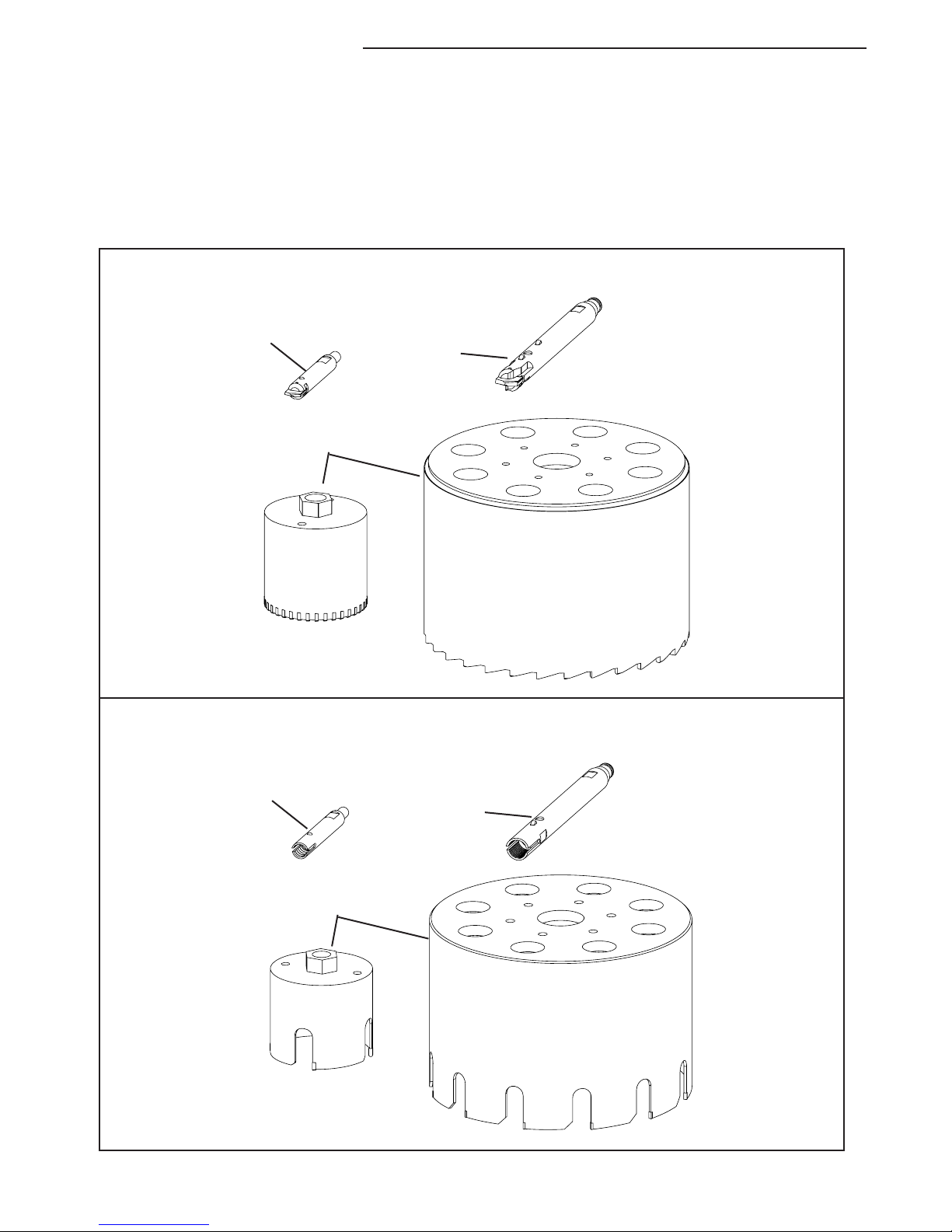
CUTTER AND PILOT IDENTIFICATION
1.Selectthepropercutterandpilotforthepipeyou'llbetapping.Seethedrawingsbelow.
TM, Shaft Nose
(4" - 12" taps)
Cutter and Pilots shown below are for use on Ductile Iron, Cast Iron and
Asbestos / Cement pipe.
TM, Shaft Nose
(4" - 12" taps)
Cutter and Pilots shown here are for use on PVC pipe.
TM, Shaft Nose
(14" - 24" taps)
Carbide Cutters
TM, Shaft Nose
(14" - 24" taps)
Carbide Cutters

7
TAPMATE™ XL-424 Operating Manual
ABOUT ADAPTER HUB SIZES
1.EnsurethatthecorrectAdapterHubissecurelyattachedtotheLeadTube.
TodeterminewhichAdapterHubyou'llneed,seethedrawingsbelow.
Note: The TapMate XL-424 is shipped from the factory without an Adapter Hub installed.
Small Adapter Hub
for use with
4" - 12" TapMate Adapter Bells.
Large Adapter Hub
for use with
14" - 24" TapMate XL-424 Adapter Bells.
8
TAPMATE™ XL-424 Operating Manual
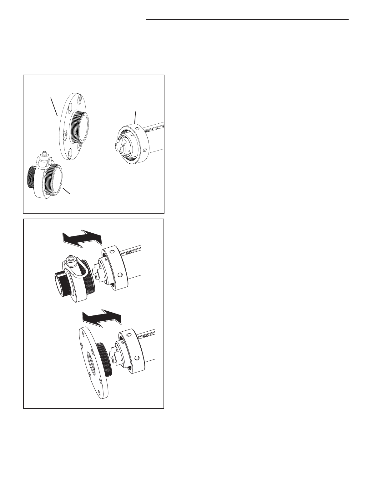
ADAPTER HUB INSTALLATION AND REMOVAL
Large Adapter
Hub
Lead Tube
Locking Collar
Small Adapter
Hub
Installation:
1. SelecttheappropriateAdapterHubforthesizeofAdapter
Belltobeused(SmallAdapterHubfor4"-12"andLarge
AdapterHubfor14"-24").
2. AlignthekeywayintheAdapterHubwiththekeyinthe
topoftheLeadTube(seedrawingatleft).
3. SlideAdapterHubovertheendoftheLeadTubeand
engagethethreadsoftheLeadTubeLockingHubCollar
(seedrawingatleft).
Large Adapter
Hub
Small Adapter
Hub

9
TAPMATE™ XL-424 Operating Manual
ADAPTER HUB INSTALLATION AND REMOVAL (cont.)
4. Tightenwithaspannerwrench.
Removal:
1. UnscrewtheAdapterHubfromtheLeadTube
LockingCollarwiththeSpannerWrench.
2. SlidetheAdapterHubotheLeadTubeand
storeinShippingCrate/WorkStation.
Large Adapter HubSmall Adapter Hub
Large Adapter HubSmall Adapter Hub
10
TAPMATE™ XL-424 Operating Manual
TAPMATE XL424 SETUP FOR 4" 12" taps:
For instructions on attaching the Large Adapter Bell (for 14" - 24" taps), turn to page 14.
1. AftertheSmallAdapterHubhasbeensecurelyattachedtothe
LeadTube,checktheTapMateAdapterBelltobesurethatthe
o-ringisinneckoftheadapter.
2. ScrewtheappropriatesizeandstyleAdapterBellontotheendof
theAdapterHub.Youshouldfeeltheo-ringcompressasyou
nishthreadingitontotheAdapterHub(seedrawingatleft).
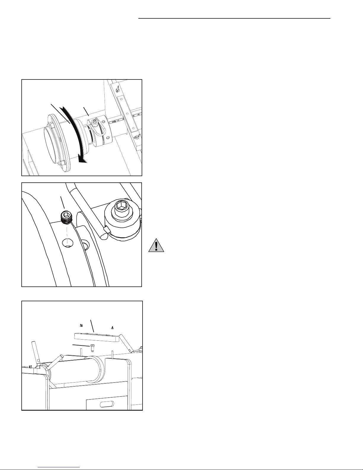
3. erearefoursetscrewholesaroundtheneckoftheadapterbell.
Continuetothreadtheadapteronuntilthenextholeisoverthe
atslotonthetopofthehub.
4. Insertonesetscrewintotheholelocatedabovetheatandusea
3/16”allenwrenchtotightenthesetscrew(seedrawingatleft).
Note: The set screw must bear ENTIRELY on the at of the Small
Adapter Hub. Otherwise, damage to the threads of the Hub under
the set screw may occur, which in turn will make the Adapter very
dicult to remove. Further damage to the threads of the Adapter Bell
may also occur as you unscrew it from the Hub.
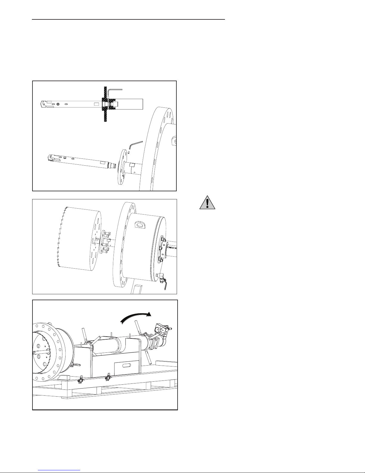
5. RemovetheBrakeTubeLockingBoltfromtheBrakeTube
(seedrawingatleft).iswillallowtheBrakeTube
torotateseperatefromtheentiremachine.Removetheback
workstationbrace.Leavethefrontworkstationbraceinplace.
Small
Adapter
Hub
Adapter Bell
(4" - 12")
Set
Screw
Brake Tube
Locking Bolt
Workstation
Rear Brace
11
TAPMATE™ XL-424 Operating Manual
TAPMATE XL424 SETUP FOR 4" 12" taps:
(cont.)
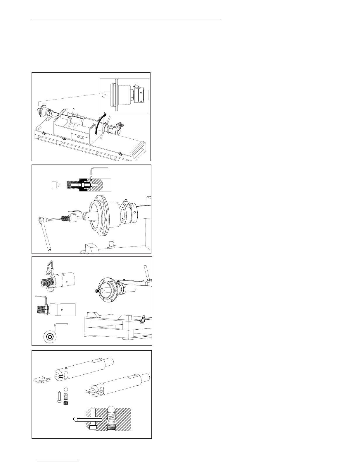
6. readtheBrakeTubedowntherustTubeby
rotatingitinaclockwisedirection,asviewedfromthe
backofthemachine(seedrawingatleft).Dothisuntil
theShaftextendsoutoftheAdapterBell.edistance
willvarydependingonthetypeandsizeofAdapter
Bellbeingused.
7. Applytheanti-gallinglubricanttotheSmallShaft
HeadBoltandstarttothreaditintotheendofthe
Shaftwiththe3/8"Allenwrench.Alighthekeyup
withthekeywayandnishscrewingtheSmallShaft
Headintoplace.Applytheanti-gallinglubricanttoboth
setscrewsandthreadthemintotheShaftusingthe1/8"
Allenwrench.eylocktheSmallShaftHeadBoltinplace,
preventingitfromlooseningduringthecuttingoperations.
8. eJamNutfacilitateseasyremovaltheShellCutters.
readtheJamNutontotheShaft.Runittothe
endofthethreads,andthenbackoonecomplete
revolution.Witha3/16"allenwrench,tightenJamNut
halvessothatthegapbetweenthemiseven
(seedrawingatleft).SecuretheJamNuthalvesby
torquingscrewstoapproximately50in-lbs.
9. TaketheTMShaftNose(orTMPVCPilot)and
examinetheretentionballsystem.Itshouldrequire
rm-to-hardpressuretodepresstheball.eball
shouldsnapbackintoplacesmoothly.Iftheballis
sticking,disassemble,andcleanthehole,balland
spring.Reassemble,andre-examinetoensuretheballis
functioning properly.
ChecktoseethattheSpadeBitintheTMShaftNose
is sharp and that it is held securely in the slot. If the
SpadeBitischippedordamaged,itshouldbereplaced.
TM Shaft Nose

12
TAPMATE™ XL-424 Operating Manual
TAPMATE XL424 SETUP FOR 4" 12" taps:
(cont.)
10. readtheTMShaftNoseorTMPVCPilot(dependingonthematerialofpipeyouaretapping)into
theendoftheShaftandtightenuntiltheshankoftheTMShaftNoseortheTMPVCPilotisushagainsttheface
oftheShaft.Duetothelongerbodylengthofthe10and12inchshellcutters,aPilotDrillExtensionmust
beattachedbetweentheShaftandtheShaftNose(orPVCPilot)andtightenedintoplaceforthesesizetaps.
Seedrawings(below)forShaftNosecongurations.
11. NowsliptheshellcutterovertheTMShaftNoseorTMPVCPilotandthreaditontotheShaftuntilitissnug
againsttheJamNut.
12. RetracttheShellcutterintotheAdapterBellbyrotatingtheBrakeTubeinacounter-clockwisedirection.eBrake
Tubewillstoprotatingwhenitshows“zero”(oralittlebeyond)ontherustTube.Locatethesetscrewholein
theBrakeTubebackoverthescaleintherustTubeandre-attachtheBrakeTubeLockingHandle.eBrake
TubeLockingHandlemaydamagetherustTubethreadsifitisn'tlocatedoverthescale.
13. CheckthattheLeadNutissittingat"zero"ontheLeadTube.
SHAFT NOSE CONFIGURATION FOR 10" 12" CUTS
TM Shaft Nose
XL Shaft TM Jam Nut
TM Pilot Drill
Extension
SHAFT NOSE CONFIGURATION FOR 4" 8" CUTS
TM Shaft Nose
XL Shaft TM Jam Nut
13
TAPMATE™ XL-424 Operating Manual
TAPMATE XL424 SETUP FOR 4" 12" taps:
(cont.)
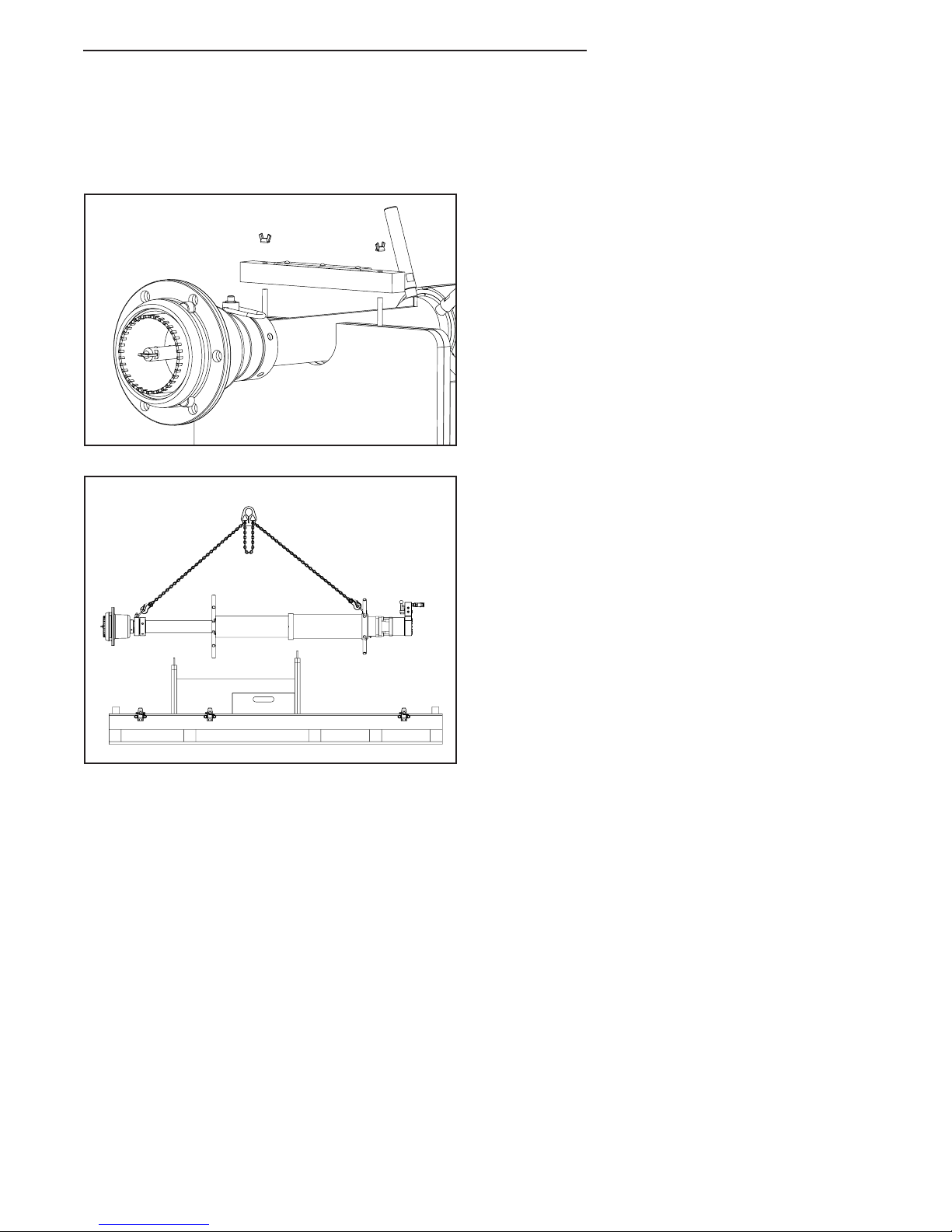
13. Removethefronttie-downbracefromthecrate.
14. eTapMateXL424isnowreadytobeliftedand
attachedtothegatevalve.Whenliftingthemachine,
usetheLiftingRingsattherearofthemachineandat
theSmallAdapterHubasyourliftpoints.Adjustthe
ChainChokersothatthemachineaslevelas
possible.
14
TAPMATE™ XL-424 Operating Manual
TAPMATE XL424 SETUP FOR 14" 24" taps:
For instructions on attaching the Small Adapter Bell (for 4" - 12" taps), go to page 8.
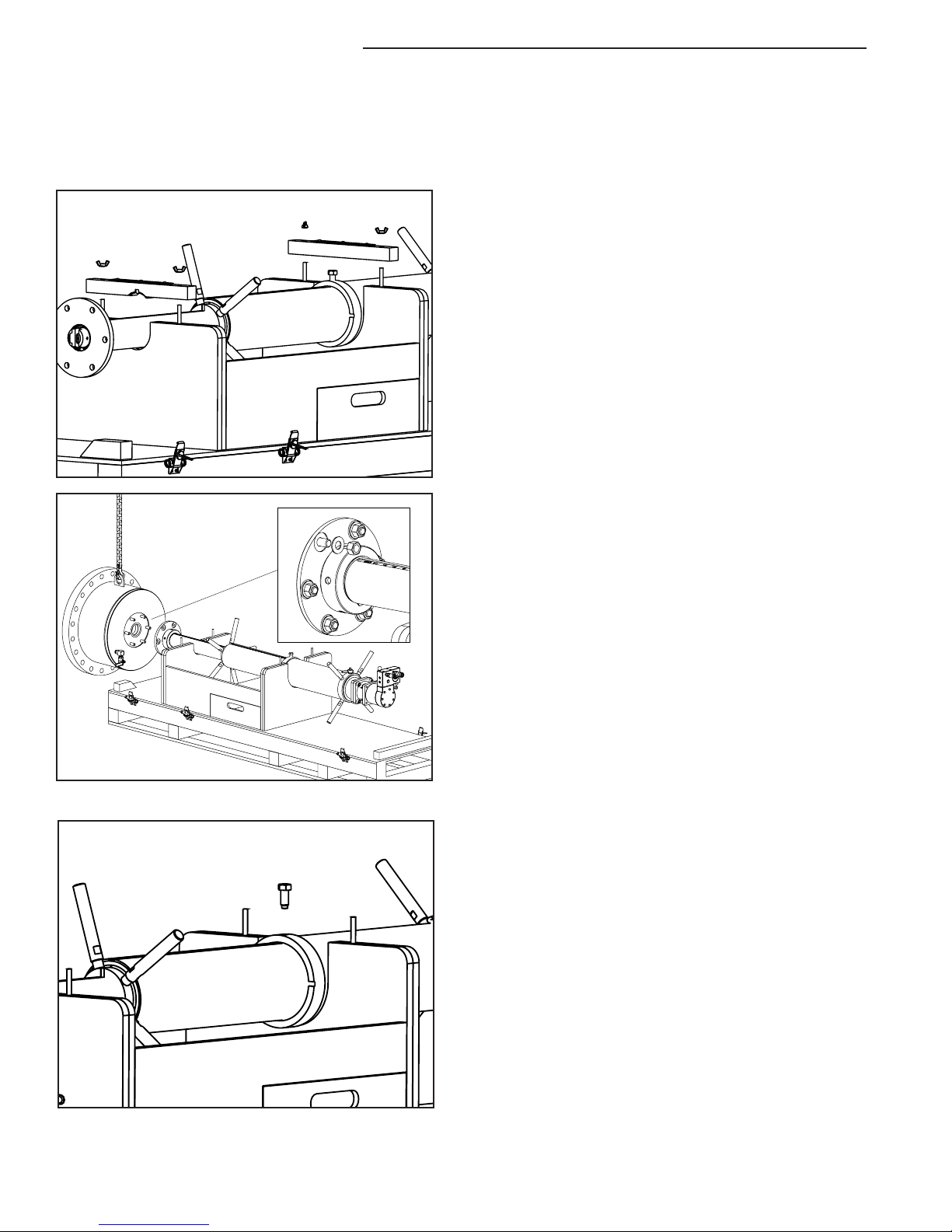
1. Removefrontandrearbracesfromworkstation.
2. WiththeLargeAdapterHubproperlyinstalledonthe
LeadTube(seestepsonpage6),liftandmovethe
appropriatesizeandstyleTapMateXL-424Adapterbell
intoplace(seedrawingatleft).
3. Removethesixnutsandwashersfromtheoutsideof
theadapter.Alsomakesurethatthegasketisinplace.
4. LifttheAdapterBellbytheliftingeye,andmove
itintoplace.eShaftgoesthroughthecenterhole
intheadapter.Carefullyslidetheadapterbolts
throughthematingholesintheLargeAdapterHub.
5. Replacethenutsandwasherbackontotheadapter
and tighten.
6. RemovetheBrakeTubeLockingBoltfromtheBrake
Tube(seedrawingatleft).iswillallowtheBrakeTube
to rotate.

15
TAPMATE™ XL-424 Operating Manual
TAPMATE XL424 SETUP FOR 14" 24" taps:
(cont.)
7. readtheBrakeTubedowntherustTubebyrotating
itinaclockwisedirection,asviewedfromthebackof
themachine(seedrawingatleft).DothisuntiltheShaft
extendsoutoftheAdapterBell.edistancewillvary
dependingonthetypeandsizeofAdapterBellbeing
used.
8. Applytheanti-gallinglubricanttotheLargeShaftHead
BoltandstarttothreaditintotheendoftheShaftwith
the3/8"Allenwrench.Alignthekeywiththekeyway
andnishscrewingtheLargeShaftHeadintoplace.
Appytheanti-gallinglubricanttobothsetscrewsand
threadthemintotheShaftusingthe1/8"Allenwrench.
eylocktheLargeShaftHeadBoltinplacepreventing
it from loosening during the cutting operation.

16
TAPMATE™ XL-424 Operating Manual
TAPMATE XL424 SETUP FOR 14" 24" taps:
(cont.)
9. TaketheTMXL-ShaftNose(orTMXL-PVCPilot)and
examinetheretentionpinsystem.Itshouldrequire
firm pressure to depress the pin, and the pin should
snapbackintoplacesmoothly.Ifthepinissticking,
disassemble,andcleanthehole,pinandspring.
Reassemble,andre-examinetoensurethepinis
functioning properly.
ChecktoseethattheSpadeBitissharpandthatitis
heldsecurelyintheslot.IftheSpadeBitischippedor
damaged,itshouldbereplaced.
TM XL Shaft Nose
17
TAPMATE™ XL-424 Operating Manual
TAPMATE XL424 SETUP FOR 14" 24" taps:
(cont.)
10. NoticethatthethreadedendsontheTM-XLShaftNose
(andtheTM-XLPVCPilot)areinterruptedbyasmooth
area.WhentheTM-ShaftNose(orTM-XLPVCPilot)
isthreadedallthewayontotheLargeShaftHead,this
smoothareawilllineupwiththetwosetscrewholes
locatedintheLargeShaftHead.readSetScrewinto
placeandtightenwithan1/8"allenwrench(seedrawing
atleft)lockingtheShaftNoseorPVCPilotintoplace.
' 11.
MovetheappropriatesizeShellCutterovertheShaft
Nose(orPVCPilot)andontothefrontbossofthe
LargeShaftHead.AlignthethroughholesoftheLarge
ShaftHeadwiththetappedholesintheCutter.Secure
withthesixCutterboltsprovided.Tightentoa
minimumof30-40ft-lbs.
12. RetracttheShellCutterintotheAdapterBellby
rotatingtheBrakeTubeinacounter-clockwisedirection.
eBrakeTubewillstoprotatingwhenitshows"zero"
ontherustTube.
CheckthattheLeadNutissittingat"zero"onthe
LeadTube.
Note: Due to the weight of some Shell Cutters,
use a suitable strap and lifting mechanism
when lifting and installing the Shell Cutter.

18
TAPMATE™ XL-424 Operating Manual
TAPMATE XL424 SETUP FOR 14" 24" taps:
(cont.)
13. eTapMateTM-XL424isnowreadytobeliftedand
attachedtothegatevalve.Whenliftingthemachine,
using the lifting loop at the end of the machine and the
loopontheadapterbell.
Note: Adjust the Chain Choker so that the machine is
lifted as level as possible.

19
TAPMATE™ XL-424 Operating Manual
ATTACHING THE TAPMATE XL424 TO THE VALVE:
eillustrationsinthissectiondepicta6”size-on-sizetapusingaRomacFTS420FabricatedSteelTappingSleeve,anMJ
byFlangegatevalveandtheTapMateXL-424machinewithanMJadapterbell.Regardlessofthesizetapyou're
performing, the steps are the same.
1. Installandassembletappingsleeveandgatevalveperthe
manufacturer'sinstructions.Pressuretestthetapping
sleeveandgatevalveassemblybeforebeginningthetap.
NOTE: At this point, you'll take some measurments to
determine the necessary depth of your tap. Record
these measurements, as you'll use these values in
subsequent steps.
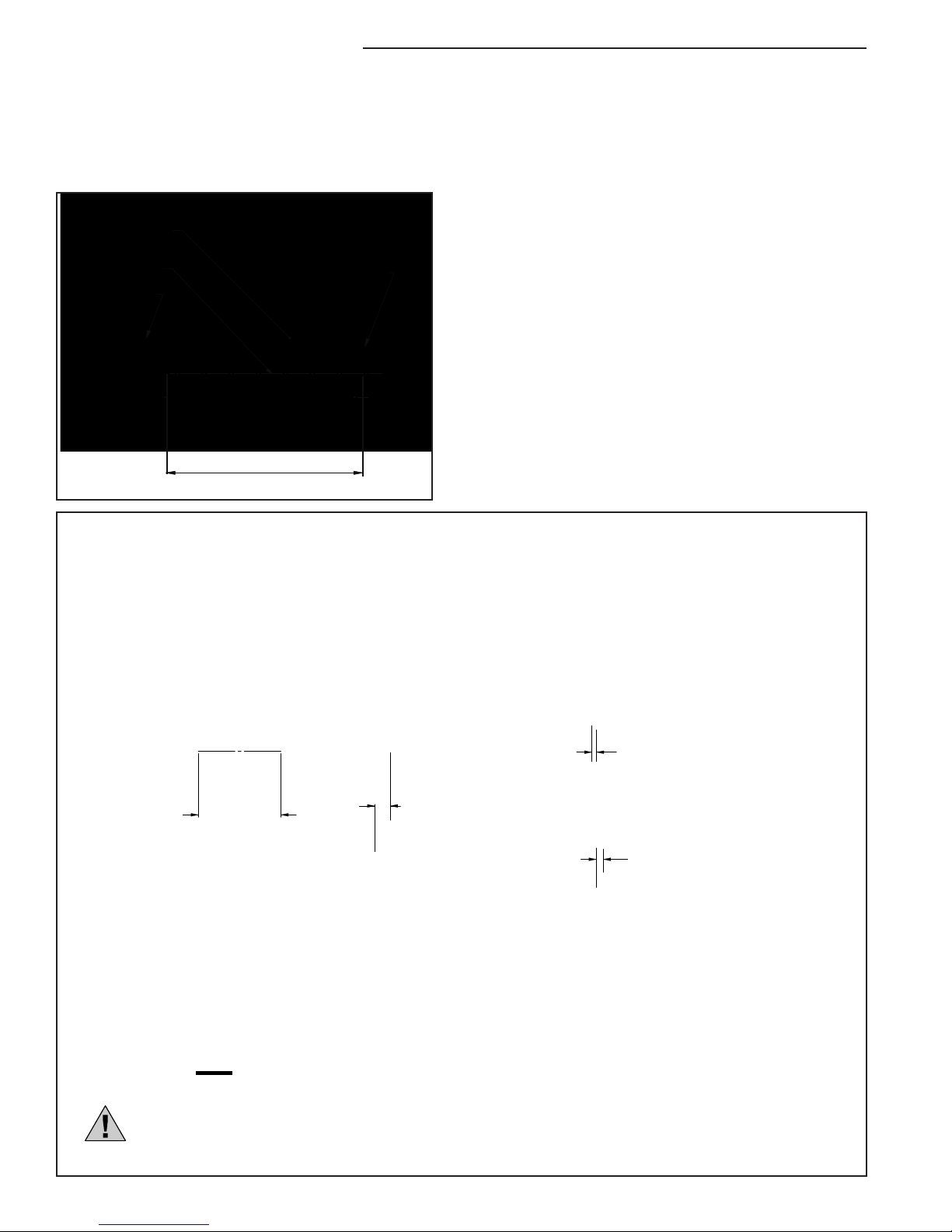
2. Withthevalvegatestillclosedfromthepressuretest,
measurethedistancefromthevalveangefacetothe
gate(seedrawingatleft).
3. WiththeShellCutterfullyretracted,takethefollowing
measurements(seedrawingsatleft)
• MeasurethedistancetheShaftNose/PVCPilot
extendsbeyondtheAdapterBellange.
• MeasurethedistancethattheShellCutterextends
beyondtheAdapterBellange.
• esedistanceareoftendierentdependingonthe
tapsizeandtheAdapterBell.
4. CarefullycomparethemeasurementstakeninSteps2
and3,toensurethattherewillbenointerference
betweentheShaftNose/PVCPilotorShellCutter,
andthegatevalvewhenthetapiscompleted.
Clearance Distance
Pilot Drill
C
L
Valve Body
Centerline of the
Waterway
Valve Gate
Distance
Cutter Clearance
Valve
Flange
Face
Tapping Sleeve Neck
Pipe
Extension Distance
Shaft Nose/PVC Pilot
Extension Distance
Shaft Nose/PVC Pilot
MJ Adapter
(without Gasket)
Distance
Cutter's Extension
Flange Adapter
Distance
Cutter's Extension
20
TAPMATE™ XL-424 Operating Manual
Distance to Pipe
Centerline of
the Waterway
Valve Gate
C
L
Pipe OD
Valve
Flange
5. Carefullyreleasethepressureinthesleeveandvalve.
OPENthevalvegatecompletely.
6. Measure,andnotethedistancefromthevalveangeto
thepipe(throughthevalve,sleeveneckandany
extensions).Recordthismeasurment,asthisvalueis
necessaryinsubsequentsteps.
Pipe
Distance to Distance of Cut
Travel Chart's
<
=
39 Inches Total Machine
Bar Travel Distance
C
L
-
+Cutter's Extension
out of Adapter
and into Valve Body
or
BORING BAR TRAVEL & DISTANCE OF CUT
7.eTapMateXL-424boringbarcantravel39inches,whichismorethanadequateformosttaps.
Beforeyoubeginyourtap,makesurethetotaldistancetocutisnotmorethan39inches.
Todeterminethedistancenecessaryforyourtap,seethedrawingbelow.
ATTACHING THE TAPMATE XL-424 TO THE VALVE:
(cont.)
Note: Conrm that the ID of the pipe is greater than the Cutter's OD.
Table of contents


