Transporter PLUS 11 MK 2 Release note
Issue : - Man/P11,02 1 Last rev: 26.08.2010
FOR THE ULTIMATE IN QUALITY AND SERVICE
PLEASE CONTACT US AT:-
The Old Airfield, Gosfield, Halstead, Essex C09 1SA
(01787) 478490 Fax :( 01787) 476047
www.transporter-engineering.com
E-mail: [email protected]
PLUS 11 MK 2 CAR TRANSPORTER
DRIVERS MANUAL

Issue : - Man/P11,02 2 Last rev: 26.08.2010
CONTENTS
DECK MAXIMUM LOADS AND LOAD SECURITY……………………………..3
OPERATION AND SAFETY SIGNS ................................................................4
CARE OF BODY PAINT WORK ......................................................................4
GENERAL SAFETY.........................................................................................4
GENERAL VEHICLE LAYOUT ........................................................................5
TYRE PRESSURES AND TORGUE SETTINGS.............................................6
MAXIMUM DECK LIFTING CAPACITIES........................................................7
DAILY SAFETY CHECKS................................................................................8
OPERATION OF THE POWER TAKE OFF UNIT (PTO).................................8
LOADING RAMPS ...........................................................................................8
OPERATING DECKS ......................................................................................9
HAND RAILS .................................................................................................10
TRAILER SUSPENSION VALVE OPERATION.............................................10
LOADING LIGHTS.........................................................................................10
COUPLING AND UNCOUPLING THE RIGID................................................ 11
UNLOADING IN THE EVENT OF A MECHANICAL FAILURE ......................12
VEHICLE SECURING SYSTEMS..................................................................13
VEHICLES ON THE TRANSPORTER...........................................................14
LOADING SEQUENCE DIAGRAMS..............................................................15
TYPICAL LOADING DIAGRAMS................................................................... 31
SERVICE FACILITIES (Listings) SUPPLIMENT SHEET
SERVICE FACILITIES (Locations) SUPPLIMENT SHEET
This manual is an important document and as such should remain with the
vehicle. It is a Health and Safety requirement that the driver can refer to the
document to establish SWL.
Before operating this transporter you must be trained in its operation and be
fully conversant with the controls. Misuse could cause injury to operator and
serious damage to the vehicle.

Issue : - Man/P11,02 3 Last rev: 26.08.2010
DECK MAXIMUM LOADS AND LOAD SECURITY
The following sets out the maximum applied load for each deck and loading
angles, subject to the following criteria being established at all times.
•Each vehicle deck maximum imposed load limit of 2,500 kgs which
must not be exceeded.
•The trailer top deck and the rigid top deck each have a combined
maximum imposed load limit of 7,500 kgs and 5,000 kgs respectively
which must not be exceeded.
•The trailer front scissor arm mechanism maximum imposed load limit of
2,500 kgs which must not be exceeded, although the hydraulic
pressure relief system is not designed to lift an imposed load in excess
of 750 kgs.
•All imposed loads should be uniformly distributed.
•All loads carried must be fully and properly secured prior to moving
decks or the vehicles carried, in accordance with your company loading
instructions. Never move the transporter unless every vehicle loaded
on it is fully and properly secured.
•The above criteria apply subject to the transporter and all its equipment
being properly maintained.
•If you are in any doubt never operate a deck or move a transporter
without contacting your manager.
OPERATION AND SAFETY SIGNS
1. Operation signs are located next to all controls.
2. Warning signs are a reminder to be alert to potential dangers in the area
shown with a risk of injury or death.
3. Caution signs are a reminder to be alert to potential dangers in the area
shown which may cause product or surrounding damage.
4. Always replace signs that have been lost or defaced.

Issue : - Man/P11,02 4 Last rev: 26.08.2010
CARE OF BODY AND PAINTWORK
The use of cold water at normal tap pressure is recommended for the first three
months, after which steam cleaning at temperatures below 60 degrees centigrade
and spraying no closer than 300 mm from the surface is permissible, with care.
Any damage to the painted surfaces, eg dents, scratches, should be treated and
repainted as soon as possible to prevent any further degradation of the bodywork.
ALWAYS ensure lubrication points, slides etc are adequately greased after the use
of high pressure or steam cleaners. Never pressure wash lifting chains.
GENERAL SAFETY
WARNING: These safety precautions are important. You must also refer to the
chassis/cab manufacturers operating and maintenance instructions together with
the Transporter recommendations. You must always abide by the laws and
regulations of the country in which you operate.
•You must fully understand all controls for operating this vehicle before use.
•You must obey all warning/cautionary and safety labels on this vehicle and
replace any that are missing or damaged.
•Carry out routine servicing as specified by Transporter and the manufacturer of
the chassis/cab.
•Always know the height of your transporter by measuring the load before
departure; adjust the height indicator accordingly.
•Transporter recommends four straps per vehicle: 2 forwards and 2 rearwards.
•Beware of overhead obstructions: bridges, trees, cables etc.
•Make sure all loose equipment is secured safely.
•Stand the vehicle on firm level ground when operating, lifting or jacking. Apply
the parking brake and chock the wheels.
•Do not exceed the lifting capacities of the decks.
•It is important that the vehicle is operated within the C & U regulations and axle,
GVW and GTW are not exceeded.
•Do not make adjustments that you do not understand.
•Do not move the decks whilst on the transporter. Never go under an
unsupported deck.
•Other persons must be kept at a safe distance while the vehicle or its equipment
is in operation.
•Check that the decks are not contaminated with oil or grease and that the straps
are stored in a manner that will not interfere with the safety of personnel working
on the deck.
•All movements on the Plus 11 MK 2 are hydraulic with the exception of the
manual loading ramps. Loosen the lock and slide the ramp out fully using the
strap; always lock the ramp in the “out position” by straddling it, keeping your
back straight then lift the ramp into the locked position. It is recommended that
the ramp is lifted off the lock by straddling the ramp and lifting it out of the
locked position before driving on the last car. After positioning the car, slide the
ramp in with the strap and lock in place.

Issue : - Man/P11,02 5 Last rev: 26.08.2010
1. Over cab platform. 13. Towing eye
2. Peak ramp. 14. Drawbar lifting pillars
3. Peak ramp flap support pin. 15. Van loading bridging plate.
4. Rigid lifting pillars. 16. Top deck front sliding ramp.
5. Main top deck. 17. Top deck rear sliding ramp.
6. Top deck kick up ramp. 18. Main top deck
7. Top deck rear extension ramp. 19. Rear pillar ladder
8. Front bumper ladder. 20. Scissor ramp inner section.
9. Hand pump valve. 21. Scissor ramp outer frame.
10. PTO/hand pump control valve. 22. Front section of kickup ramp.
11. Hydraulic/air control valves. 23. Kick up ramp
12. Towing coupling. 24. Well deck ramps
25. Hydraulic/air control valves.
26. Park and Shunt valve
(offside).
27. EBS diagnostics socket.
28. Bogie decking
29. Fold down step for rear ladder.
30. Rear end section.
31. Manual loading ramps and
stowage.
1
2
3 4
5 6
4
7 15 16
14
17
18 19
14
21
24
22
23
8
9 10
11
12
13
2
0
28
25 26
27
29
30
31
GENERAL VEHICLE LAYOUT
RIGID
DRAWBAR

Issue : - Man/P11,02 6 Last rev: 26.08.2010
130 PS1 90 PSI Trailer tyres all 124 PSI
315/70 R22.5 315/60 R22.5 295/60 R22.5 (150/147 L Rated)
TORQUE SETTINGS
Wheels Torque M22x1.5 @ 570-630 Nm (445 lb ft)
Tow Hitch Bolt Torque M20 (8.8) @ 410 Nm (330 lb ft)
Tow Hitch Castellated Nut @ 500 Nm (360 lb ft)
Tow Eye Bolts Torque M20 (10.9) @ 610 Nm (450 lb ft)
TYRE PRESSURES AND TORQUE SETTINGS

Issue : - Man/P11,02 7 Last rev: 26.08.2010
The weights indicated are the maximum amounts that can be lifted by individual
decks and are not a guide to the legal capacity of the transporter. Gross vehicle
weights vary depending upon the axle configuration of the rigid.
Five axle road trains gross train weight 38000KG
Six axle road trains gross train weight 41000KG
Trailer gross 22100KG
MAXIMUM DECK LIFTING CAPACITIES
PEAK RAMP
2500 KG
KICKUP RAMP
2500 KG
TOP DECK (total)
5000 KG
FRONT RAMP
2500 KG
SLIDING RAMP
2500 KG
TOP DECK (total)
7500 KG
MAXIMUM DOWN FORCE
ON COUPLING
1000 KG
SCISSOR RAMP FRONT
USE AS LOADING AID
(LIFTING CAPACITY 750 KG)
SCISSOR RAMP
REAR
1750 KG
KICKUP FRONT
RAMP
2500 KG
KICK UP REAR
5000 KG

Issue : - Man/P11,02 8 Last rev: 26.08.2010
DAILY SAFETY CHECKS
A visual inspection should be conducted daily on the following items:
1. All routine driver checks as set out in the Guide to Maintaining
Roadworthiness should be performed to the rigid unit and trailer. In addition
the following items must be checked.
2. Security of the front ladder.
3. Safety hand rails are all secure and complete with no visual damage (see the
hand rails section).
4. Securing straps and bollards are working correctly, with no cuts to straps or
defects to bollards.
5. Make sure that all straps are stowed securely, clear of all moving parts.
6. Visually inspect the rigid coupling, connecting pipes and suzie cables for
defects.
ENGAGING OPERATING AND DISENGAGING THE POWER TAKE OFF (PTO)
Both trailer hydraulic pipes must be coupled before attempting to perform the
following procedure. A link pipe must be used if not trailer is coupled.
1. Make sure that the air is at full pressure.
2. Press the clutch pedal down keeping it disengaged.
3. Engage the PTO using the switch in the cab.
4. Slowly re-engage the clutch.
5. It may be necessary to increase the engine RPM to a maximum of 800 RPM.
This will be achieved by either a hand throttle or the cruise control.
6. To disengage the PTO, press down the clutch pedal keeping it disengaged.
7. Switch off the PTO.
8. Re-engage the clutch gently.
REMOVING LOADING RAMPS
Always bend your knees and not your back when moving ramps. When tipping a
loaded vehicle with a car in position 11, slide the ramps out to maximum and lift into
locating lugs after this first car has been removed.
1. Make sure the transporter is on level ground.
2. Release the loading ramp’s stowage pin.
3. Use the straps to draw out the loading ramp lifting initially.
4. Stand with a leg either side of the ramp and pull out to full extent.
5. Lift ramp onto the locating lugs. The ramps are now secure and ready for loading.
REPLACING LOADING RAMPS
Always bend your knees and not your back when moving ramps. It is good practice
to lift the ramps off the locating lugs before driving the last car into position 11.
1. Stand with a leg either side of the loading ramp and lift it off the locating lugs.
2. Using the webbing strap to draw the ramp back to its stowed location.
3. Use the locking pin to secure the ramp in place, making sure the ramp straps
are retained behind the catch.

Issue : - Man/P11,02 9 Last rev: 26.08.2010
Control handles
Lock release air buttons
OPERATING DECKS
Important! All personnel must be clear of the vehicle before operating any
controls.
LIFTING DECKS
1. Pull the relevant control handle towards you from its neutral position. The
deck should now raise as the handle is held in this position.
2. When the deck is at the required height, return the lever to the neutral position
then lower the deck onto the locking rack.
The deck must be supported by the locking rack, not by the chain or
hydraulic cylinders.
LOWERING DECKS
1. Pull the relevant control handle towards you from its neutral position, so that
the deck lifts enough to release the locking pawls on both sides.
2. Press in and hold the relevant locking release air button.
3. Push the control handle away from you whilst keeping the air button de-
pressed, the deck should now lower. Always check the deck is lowering
evenly.
4. When the deck has reached its required level, return the lever to the neutral
position.
5. Release the air button to re-engage the deck locks.
6. Further lower the deck so that the pawl is supported by the locking rack.
The locking rack blocks are spaced at 50mm intervals.

Issue : - Man/P11,02 10 Last rev: 26.08.2010
Most decks and ramps are operated using the above method, but some slide
ramps have a double pilot check valve as a locking mechanism instead of a locking
pawl. Always check that the control levers return to neutral when released.
HAND RAILS
The transporter has been fitted with a hand rail system that meets Health and
Safety regulations at time of manufacture. Any retrospective change in the
legislation after the vehicle has entered service is the responsibility of the operator.
The system must be maintained and defected if:
Posts are missing.
Posts have been damaged, distorted or corroded.
Ropes are not tensioned or defective.
TRAILER SUSPENSION RAISE/LOWERVALVE (Optional fitting)
The suspension valve can be used to raise or lower the trailer suspension height, to
aid ground clearance when loading and unloading certain vehicles. This valve
must be returned to the main ride height position as shown before setting off. The
vehicle may be driven with the valve in the high position to aid loading the
transporter on and off ferries.
LOADING LIGHTS
Loading lights are a standard fitting on the Transporter car transporters. These are
operated from inside the cab using the trailer coupling light switch. Extra care
should be taken when working in the dark – if possible position the vehicle in a well
lit area.

Issue : - Man/P11,02 11 Last rev: 26.08.2010
Coupling in open position Coupling in locked position
UNCOUPLING THE RIGID UNIT
Before carrying out the following procedure, ensure that the transporter is on
firm level ground, with a suitable block to support the trailer front cross
member, ideally in the centre.
1. Apply the trailer parking brake.
2. Raise the rigid suspension.
3. Put the suitable supporting block under the trailer front cross member in the
centre.
4. Lower the suspension on to the supporting block, so that the towing eye is in
the centre of the coupling (ie there should be a gap at the top and bottom).
5. Disconnect all suzies and hydraulic pipe connections.
6. Lift the coupling pin release lever (you may have to rock the truck to get the
pin to release).
7. Carefully drive the rigid away from the drawbar slowly.
8. Caution Do not put you hand in the open coupling jaws, it may snap shut. To
close the coupling, push the lever with your hand in the opening direction.
The pin will locate in the locked position.
RE-COUPLING THE RIGID UNIT
1. Make sure that the coupling pin release handle is in the raised position.
2. Reverse the rigid unit to the trailer checking that the coupling is central to the
towing eye; if so reverse onto the eye (you may have to rock the unit
backwards and forwards to fully engage). Make sure that the coupling has
fully locked shut and the lock control pin is home. Apply the truck parking
brake.
3. Raise the rigid unit suspension and connect all the ‘suzies’ and hydraulic
pipes.
4. Remove the block from under the trailer and reset the suspension of the rigid
unit to its normal ride height position.

Issue : - Man/P11,02 12 Last rev: 26.08.2010
5. Release the trailer parking brake.
UNLOADING IN THE EVENT OF A MECHANICAL FAILURE
You will require adequate air pressure to enable the locking pawl air valves to
operate.
Should power be lost to the PTO pump, follow the procedure listed below.
1. Switch the change over control valve (located behind the main rigid control
handles) from the PTO pump to the hand pump position, turning the lever 90
degrees. (See photos above).
2. Place the supplied handle into the hand pump valve. This valve is situated
next to the main rigid control levers.
3. The control handle for the deck you want to move will have to be pulled
towards you and held open, whilst at the same time the hand pump is
manually pumped up and down, lifting the deck so that the locking pawls can
be released.
4. When the locking pawl has been released, de-press the air button whilst
lowering the deck with the control handle. (This operation may be slower than
usual).
Issue : - Man/P11,02 13 Last rev: 26.08.2010
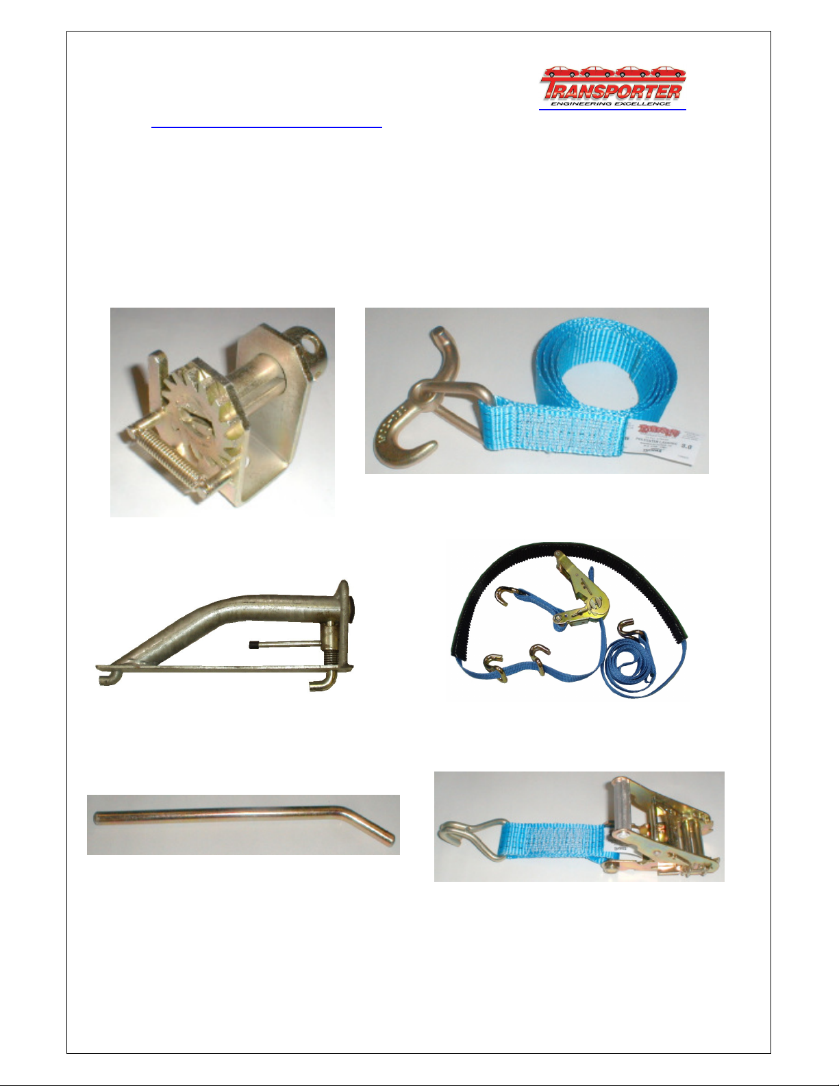
VEHICLE SECURING SYSTEMS
The load restraint system used on the transporter can either be bollards and straps,
mobile straps, or wheel chocks, or you may have a mixture of all three systems.
Pulling directions must be considered when securing vehicles on the transporter, as
a guideline two straps pulling in either direction (ie forwards and backwards), with
chocks on each wheel should be adequate. Your company should be able to
advise you on the system and number of restraints required for particular loads
being carried.
Bollard
Swivel T hook and strap
Over wheel Strap Assembly
Tommy Bar
A typical wheel chock
Hand Ratchet

Issue : - Man/P11,02 14 Last rev: 26.08.2010
CAUTION
BEFORE TILTING CAB
1. Remove or hinge the front ladder forward. Failure to carry out this procedure
will damage the cab.
2. You must ensure the peak ramp is DOWN to the stops before raising it
over the cab platform.
3. Failure to carry out this procedure will severely damage the lifting mechanism.
LOADING VEHICLES ONTO THE TRANSPORTER
1. Before loading ensure that all the decks are set in their correct position for
loading, with all the straps and wheel chocks stowed safely out of the way.
2. Check that visibility is good, with frost etc cleared from vehicle windows.
3. Check that the ground clearance is adequate.
4. When the vehicle is loaded into position, apply the hand brake fully and leave
the vehicle in first gear (or in park position on automatics).
LOADING THE TRANSPORTER PLUS 11
Before carrying out the following procedure, make sure you have had sufficient
training and are fully conversant with all the controls and operation of the
transporter. You should also be wearing suitable safety equipment, eg high visibility
jacket, boots and gloves. Remove all sharp objects such as rings and watches that
could damage the vehicles during loading.
The following pages will guide you through the method of loading the Plus 11
Transporter.
(The procedure for unloading the transporter is generally as for loading it, but in
reverse).
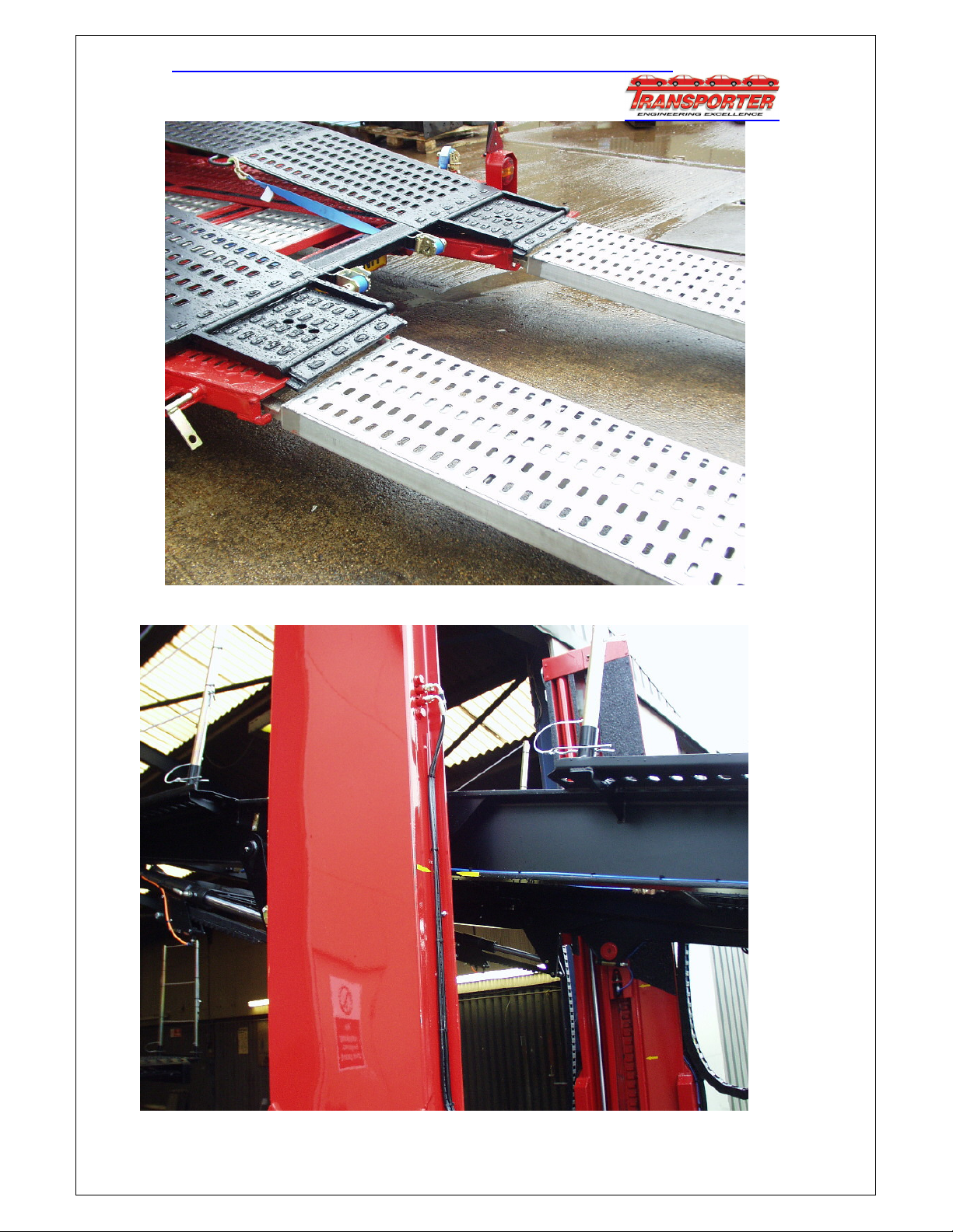
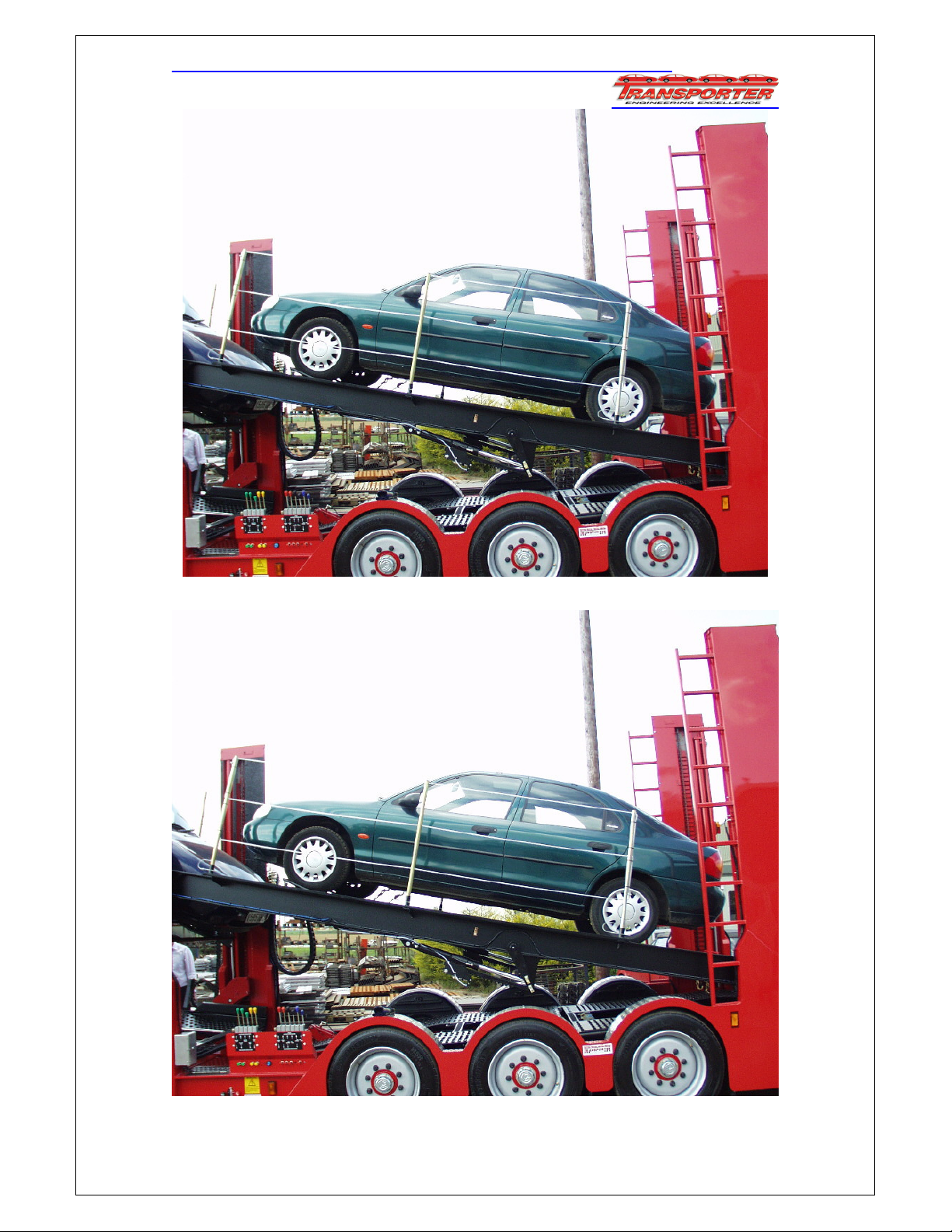
PLUS 11 MK 2 RIGID AND DRAWBAR LOADING SEQUENCE
Issue : - Man/P11,02 15 Last rev: 26.08.2010
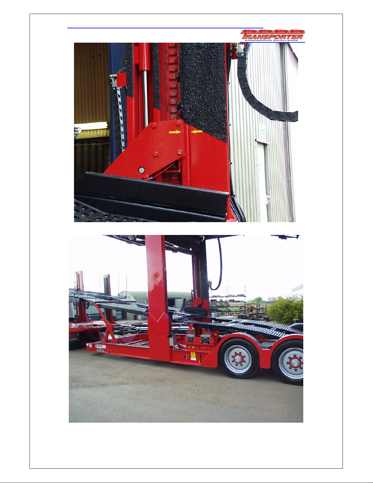
Remove loading ramp stowage pins, pull out loading ramps and lift into locked position.
Set trailer top deck front to align arrows and fully lower rear to loading angle.
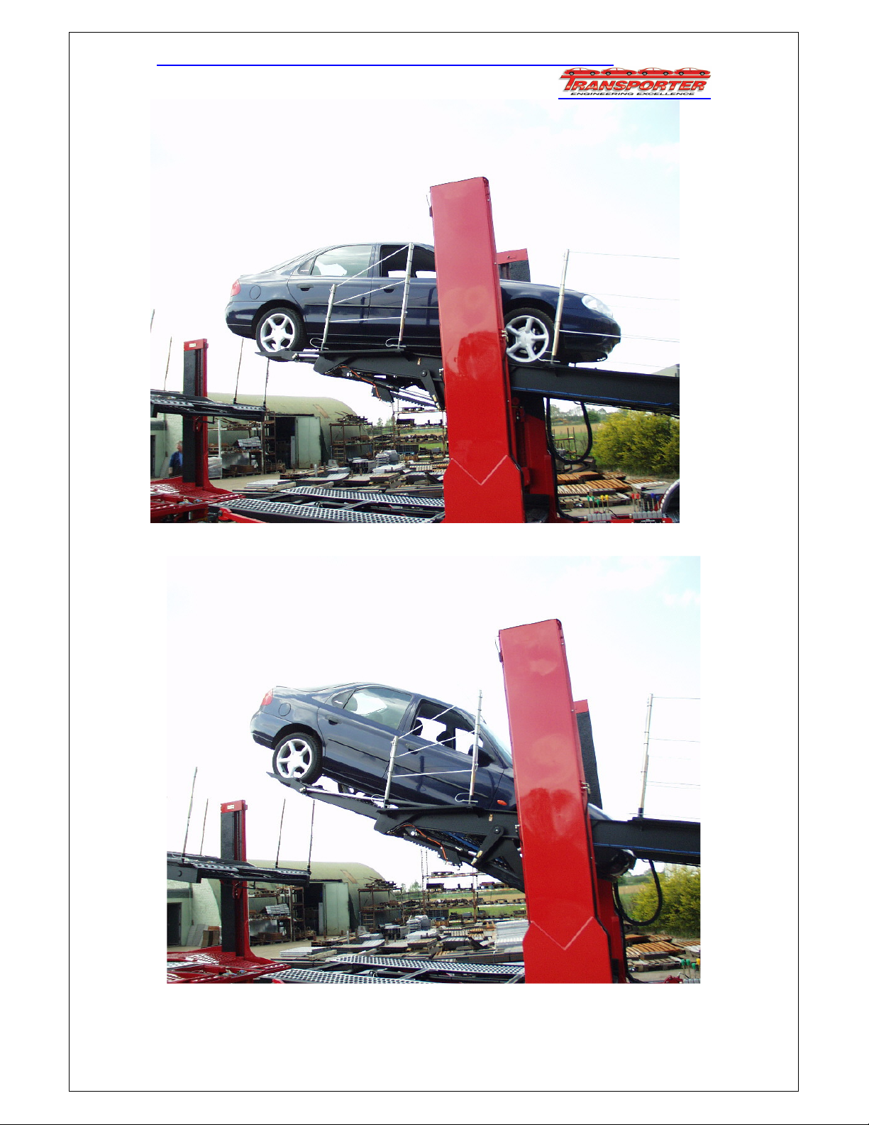
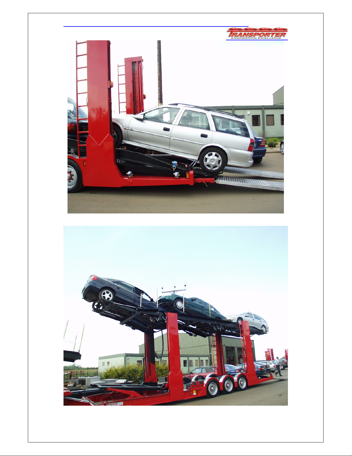
PLUS 11 MK 2 RIGID AND DRAWBAR LOADING SEQUENCE
Issue : - Man/P11,02 16 Last rev: 26.08.2010
Car 1: Reverse car onto front drop ramp.
Secure car to ramp, fully extend ramp and lower to desired height.
PLUS 11 MK 2 RIGID AND DRAWBAR LOADING SEQUENCE
Issue : - Man/P11,02 17 Last rev: 26.08.2010
Car 2: Fold over front wheel stops, drive car onto ramp up to stops.
Secure car to ramp, extend and lower to desired position.
PLUS 11 MK 2 RIGID AND DRAWBAR LOADING SEQUENCE
Issue : - Man/P11,02 18 Last rev: 26.08.2010
Car 3: Drive car onto rear of deck, lift up wheel stop and secure.
Adjust clearance between cars and raise top deck to maximum height.
PLUS 11 MK 2 RIGID AND DRAWBAR LOADING SEQUENCE
Issue : - Man/P11,02 19 Last rev: 26.08.2010
Adjust well deck rear to align with upper arrows on pillar and lower onto locks.
Raise front of well deck scissor and front of kickup
ramp to maximum, lowering ramps onto their locks.
PLUS 11 MK 2 RIGID AND DRAWBAR LOADING SEQUENCE
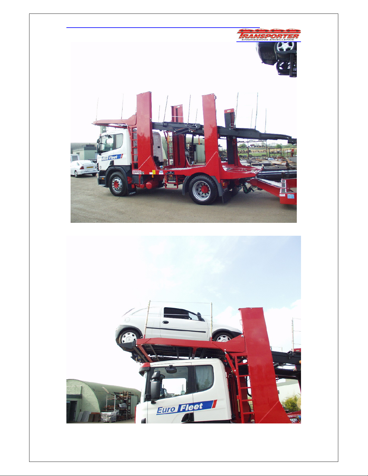
Issue : - Man/P11,02 20 Last rev: 26.08.2010
Raise over cab platform slightly, and adjust top deck to bridge between peak ramp and trailer.
Car 4: Reverse car onto peak ramp.
Table of contents
Other Transporter Farm Equipment manuals

Popular Farm Equipment manuals by other brands


Neogen Corporation
Neogen Corporation Electro Jac 6 Operator's manual

AGCO
AGCO Challenger RoGator 600C Workshop service manual

Vaderstad
Vaderstad TopDown TD 300 Series quick start

Farm King
Farm King 1684 Operator and parts manual

HEK
HEK GTP Dual T 1500 user manual

Montag
Montag Fortifier 2212 Operator's manual