Transporter Voyager S7 2017 User manual
TRANSPORTER
Engineering Excellence
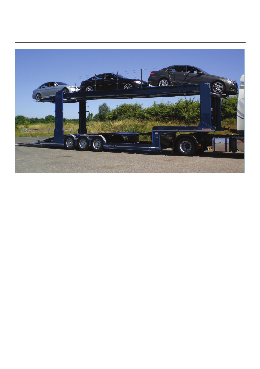
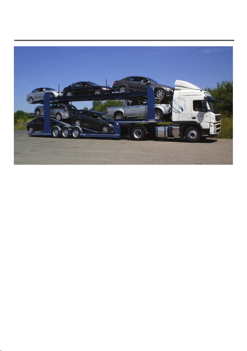
Voyager S7
Car Transporter Driver Loading Manual

3

3
Section Page
Deck Maximum Loads & Safety Signs 4
Paintwork & General Safety 5
Safety Checks & Power Take O (PTO) 6
Hydraulic Valve Controls 7
Operating Decks 8
Loading Lights & Hand Rails 9
Smart Board 10
Loading the Transporter: Loading Ramps 11
Loading the Transporter: Top Deck Front Flap 12
Loading the Transporter: Top Deck 13 - 14
Loading the Transporter: Swan Neck & Kick Up 15 - 16
Loading the Transporter: Kick Up 17 - 18
Loading the Transporter: Final Car 19 - 20
CONTENT

45
DECK MAXIMUM LOAD AND LOAD SECURITY
The following sets out the maximum applied load for each deck and load security:
Top deck complete 8,500kgs
Each lower deck should not exceed 2,800kgs
• All imposed loads should be uniformly distributed.
• All loads carried must be fully and properly secured in accordance with your company
loading instructions. Never move the transporter unless every loaded vehicle is fully and
properly secured.
• The above criteria apply subject to the transporter and all its equipment being correctly
maintained.
• If you are in any doubt never operate a deck or move a transporter without rst contacting
your manager.
OPERATION AND SAFETY SIGNS
• Operation signs are located next to all controls.
• Warning signs are a reminder to be alert to potential dangers in the area shown with a risk of
injury or death.
• Caution signs are a reminder to be alert to potential dangers in the area shown which may
cause product or surrounding damage.
• Always replace signs that have been lost or defaced.

45
CARE OF BODY & PAINTWORK
The use of cold water at normal tap pressure is recommended for the rst three months, after
which time hot wash at temperatures below 60 degrees centigrade and spraying no closer
than 300 mm from the surface is permissible with care.
Any damage to the painted surfaces, e.g. dents, scratches, should be treated and repainted as
soon as possible to prevent any further degradation of the bodywork.
ALWAYS ensure lubrication points, slides etc are adequately greased after the use of high
pressure or steam cleaners. Never pressure wash lifting chains.
GENERAL SAFETY
WARNING: These safety precautions are important. You must refer to the chassis/cab
manufacturers operating and maintenance instructions together with the Transporter
recommendations. You must always abide by the laws and regulations of the country in which
you operate.
• You must fully understand all controls for operating this vehicle before use.
• You must obey all warning/cautionary and safety labels on this vehicle and replace any that
are missing or damaged.
• Carry out routine servicing as specied by Transporter.
• Always know the height of your transporter by measuring the load before departure; adjust
the height indicator accordingly.
• Transporter recommends four straps per vehicle: 2 forwards and 2 rearwards.
• Beware of overhead obstructions: bridges, trees, cables etc.
• Make sure all loose equipment is secured safely.
• Stand the vehicle on rm level ground when operating, lifting or jacking. Apply the parking
brake and chock the wheels.
• Do not exceed the lifting capacities of the decks.
• It is important that the vehicle is operated within the C & U regulations and axle GVW and
GTW are not exceeded.
• Do not make any adjustments that you do not understand.
• Do not move the decks whilst on the transporter. Never go under an unsupported deck.
• Other persons must be kept at a safe distance while the vehicle or its equipment is in
operation.
• Check that the decks are not contaminated with oil or grease and that the straps are stored
in a manner that will not interfere with the safety of personnel working on the deck.
• All movements on the equipment are hydraulic.

67
SAFETY CHECKS
A visual inspection should be conducted daily on the following items:
All routine driver checks as set out in the Guide to Maintaining Roadworthiness should be
performed to the vehicle.
In addition the following items must be checked.
• Safety hand rails are all secure and complete with no visual damage (see the hand rails
section, page 8)
• Securing straps and bollards/ratchets are working correctly, with no cuts to straps or
defects to bollards/ratchets.
• Make sure that all straps are stowed securely, clear of all moving parts.
ENGAGING & DISENGAGING
THE POWER TAKE OFF PTO
• Make sure that the air is at full pressure.
• Press the clutch pedal down keeping it disengaged.
• Engage the PTO using the switch in the cab.
• Slowly re-engage the clutch.
• It may be necessary to increase the engine RPM to a maximum of 800 RPM. This will be
achieved by either a hand throttle or the cruise control.
• To disengage the PTO, press down the clutch pedal keeping it disengaged.
• Switch o the PTO.
• Re-engage the clutch gently.

67
HYDRAULIC VALVE CONTROLS
A hydraulic control valve bank is tted to the nearside of the vehicle.
The levers are colour coordinated and have a corresponding air lock button where necessary.
• Top Deck: Red levers with corresponding air lock buttons.
• Swan Neck Flap: Blue lever, no air lock.
• Kick Up Front: Yellow lever, no air lock.
• Kick Up Prop: Short Blue lever, no air lock.
• Kick Up Rear: Yellow lever with corresponding air lock button.
• Loading Ramps: Black lever, no air lock.

89
OPERATING DECKS
IMPORTANT! All personnel must be clear of the vehicle before operating any
controls. Always check that the control levers return to neutral when released.
LIFTING DECKS
• Pull the relevant control handle towards you from its neutral position. The deck should now
rise as the handle is held in this position.
• When the deck is at the required height, return the lever to the neutral position and where
present lower the deck onto the locking rack.
Where present the deck must always be supported by the locking rack,
NEVER by the chain or hydraulic cylinders.
LOWERING DECKS
• Push the relevant control handle away from you from its neutral position. The deck should
now lower as the handle is held in this position.
• When the deck is at the required height, return the lever to the neutral position.
LOWERING DECKS WITH LOCKING RACKS
• Pull the relevant control handle towards you from its neutral position, so that the deck lifts
enough to release the locking pawls on both sides.
• Press in and hold the relevant locking release air button.
• Push the control handle away from you whilst keeping the air button de-pressed, the deck
will now lower.
• When the deck has reached its required level, return the lever to the neutral position.
• Release the air button to re-engage the deck locks.
• Further lower the deck so that the pawl is supported by the locking rack.
89
LOADING LIGHTS
Loading lights are a standard tting on Transporter car
transporters; these lights are operated from the switch
on the valve bank.
Side lights must be switched on for lights to work.
Fuses for the Loading Lights are located in the vehicle
cab fuse box compartment.
HAND RAILS
The transporter has been tted with a hand rail system that meets Health and Safety
Regulations at time of manufacture, compliance with any retrospective change in the
legislation after the vehicle has entered service is the responsibility of the operator.
The system must be maintained and defected if:
• Posts are missing.
• Posts have been damaged, distorted or corroded.
• Ropes are not tensioned, frayed or broken.
• Any defects to the hand rail system are present.
• It is in the drivers own interests to include the hand rail system in the daily walk
round checks.

10 11
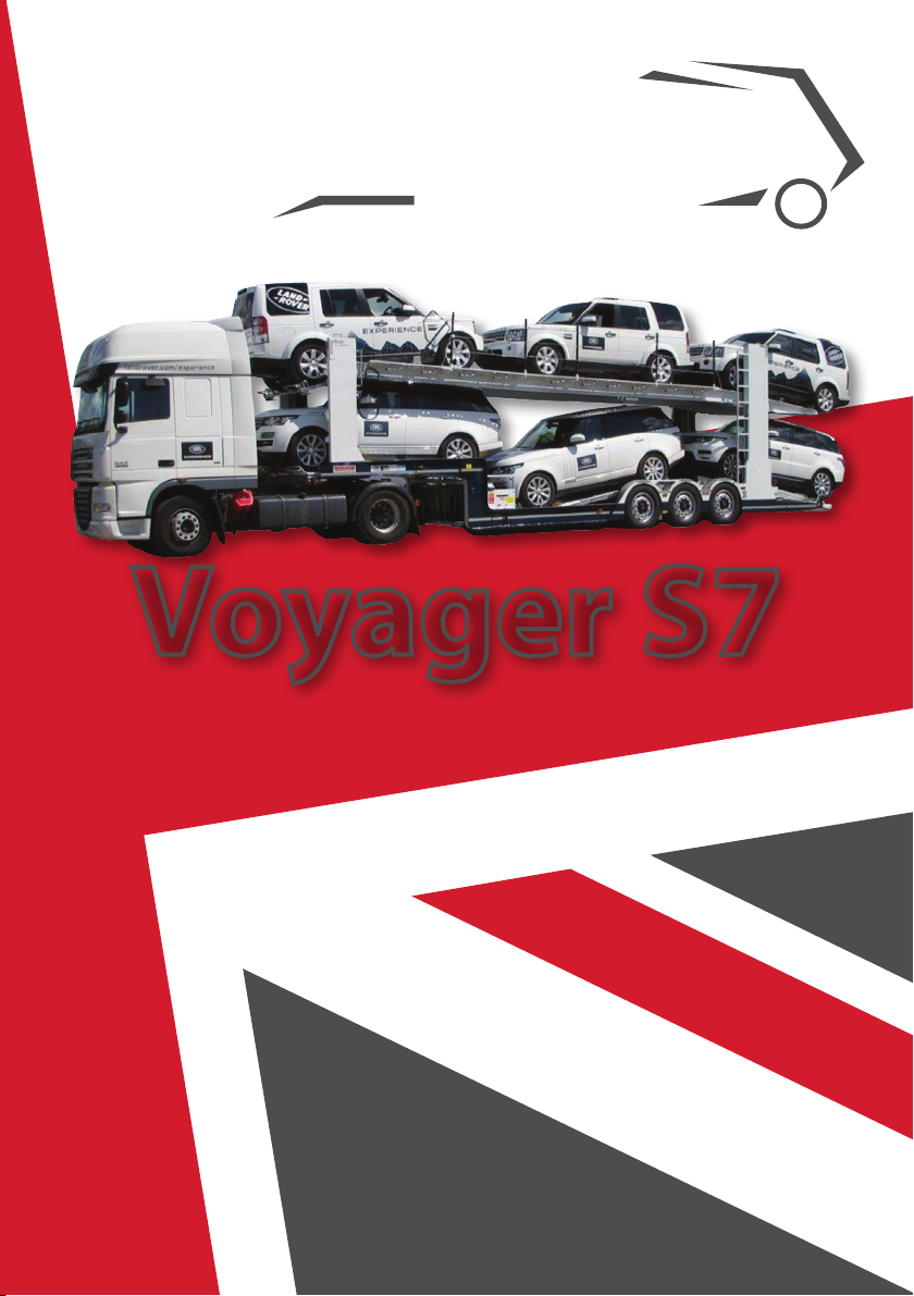
SMART BOARD
10 11
LOADING THE TRANSPORTER
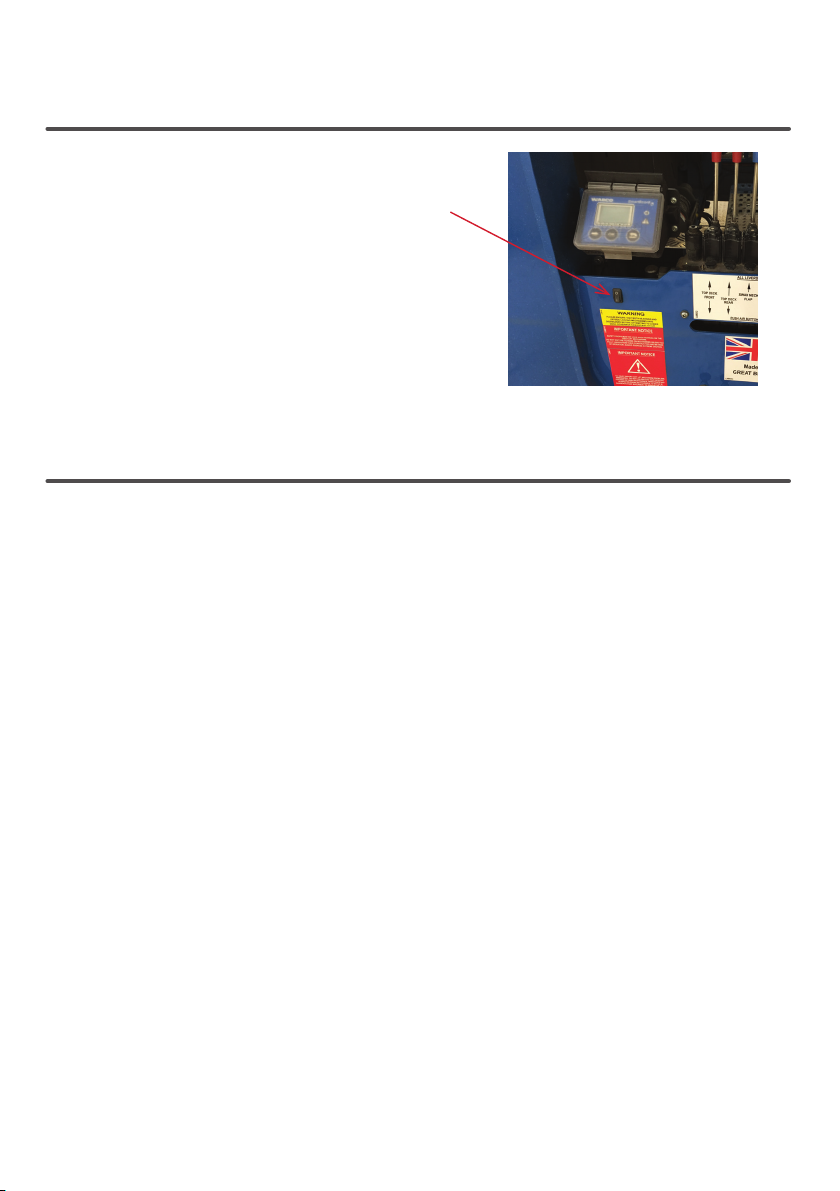
LOADING RAMPS
FULLY EXTEND BOTH O/S AND N/S HYDRAULIC LOADING RAMPS. UNLOCK THE
MANUAL RAMPS BY FOLDING OVER THE LOCKING BAR.
FULLY EXTEND THE MANUAL LOADING RAMPS BY LIFTING AND PULLING THE RAMP
BY THE ORANGE STRAP. ONCE FULLY EXTENDED, LOCK THE RAMP IN PLACE WITH THE
LOCKING BAR.

12 13
POSITION THE FRONT OF THE TOP DECK ONTO THE SUPPORT PINS LOCATED ON THE
FRONT PILLARS.
THE TOP DECK FRONT RAMP CAN BE SET AT TWO DIFFERENT ANGLES. THE PICTURE
SHOWS THE RAMPS SPRING LOADED PINS SET TO GIVE THE MINIMUM DROP ANGLE.
TO ADJUST THE DROP ANGLE TO MAXIMUM, SUPPORT THE TOP DECK ON THE PINS
HOUSED ON THE FRONT PILLARS AND PULL THE SPRING LOADED PINS BACK AND
LOCK THE HANDLES BEHIND THE LOCK PINS.
LOADING THE TRANSPORTER
TOP DECK FRONT FLAP
12 13
FULLY LOWER THE “PROP” DECK AND THE REAR KICK UP DECK. ENSURE WHEEL STOPS
ON THE REAR KICK UP ARE FOLDED OVER TOWARDS THE LOADING RAMPS, THEN
LOWER THE TOP DECK REAR ONTO THE REAR KICK UP DECK. RELEASE THE TOP DECK
WHEEL STOP LOCKS AND LOWER THE WHEEL STOPS.
LOAD THE TOP DECK AND SECURE THE VEHICLES TO THE DECK.
REFER TO YOUR OWN TIEDOWN POLICY FOR SECURING THE VEHICLES TO THE
TRANSPORTER.
LOADING THE TRANSPORTER TOP DECK
14 15
FULLY RAISE THE TOP DECK BY LIFTING THE REAR OF THE TOP DECK FIRST AND THEN
THE FRONT AND REAR IN EQUAL AMMOUNTS.
LOADING THE TRANSPORTER TOP DECK

14 15
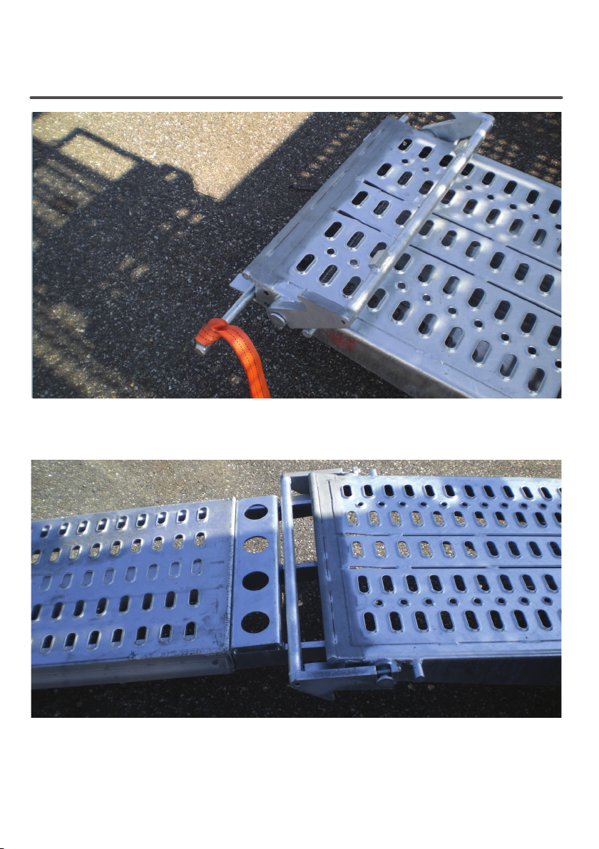
FULLY RAISE THE KICK UP PROP AND THE FRONT KICK UP RAMP.
ADJUST THE HEIGHT OF THE SWAN NECK FLAP TO LEVEL UP WITH THE FRONT OF THE
KICK UP RAMP.
LOADING THE TRANSPORTER
SWAN NECK & KICK UP
16 17
LOAD VEHICLE ONTO THE FIFTH WHEEL DECK AND SECURE VEHICLE TO THE
TRANSPORTER.
RAISE THE SWAN NECK FLAP TO MAXIMUM AND LOWER THE FRONT KICK UP TO BE
LEVEL WITH THE TOP OF THE CHASSIS FRAME.
LOADING THE TRANSPORTER
SWAN NECK & KICK UP
16 17
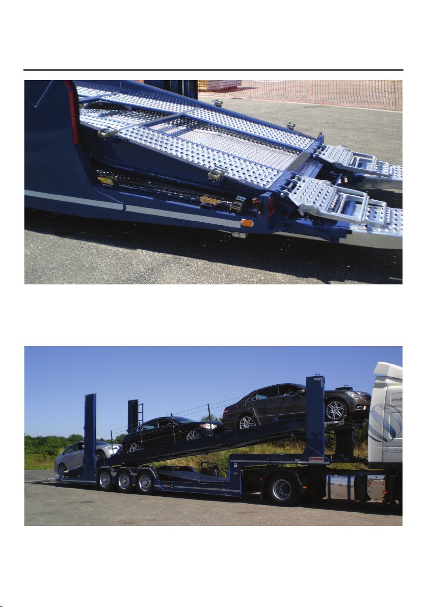
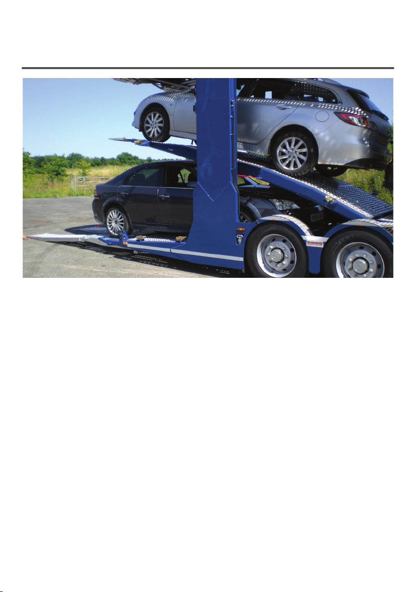
LOAD VEHICLE ONTO THE FRONT KICK UP RAMP AND SECURE THE VEHICLE TO THE
TRANSPORTER.
REVERSE VEHICLE ONTO THE REAR KICK UP RAMP AND SECURE THE VEHICLE TO
THE TRANSPORTER.
LOADING THE TRANSPORTER KICK UP

18 19
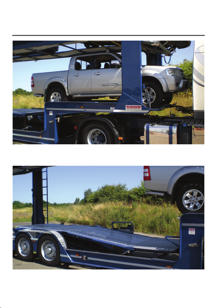
LOWER THE KICK UP PROP AND THE FRONT KICK UP RAMP, THEN RAISE THE REAR
KICK UP TO A HEIGHT TO ALLOW THE LOADING OF THE LAST CAR.
BEFORE LOADING THE LAST CAR FOLD OUT THE WHEEL STOPS.
NOTE: WHEN UNLOADING THE TRANSPORTER REMEMBER TO FOLD THE WHEEL STOPS
BACK OVER TO THE STOWED POSITION
LOADING THE TRANSPORTER KICK UP
18 19
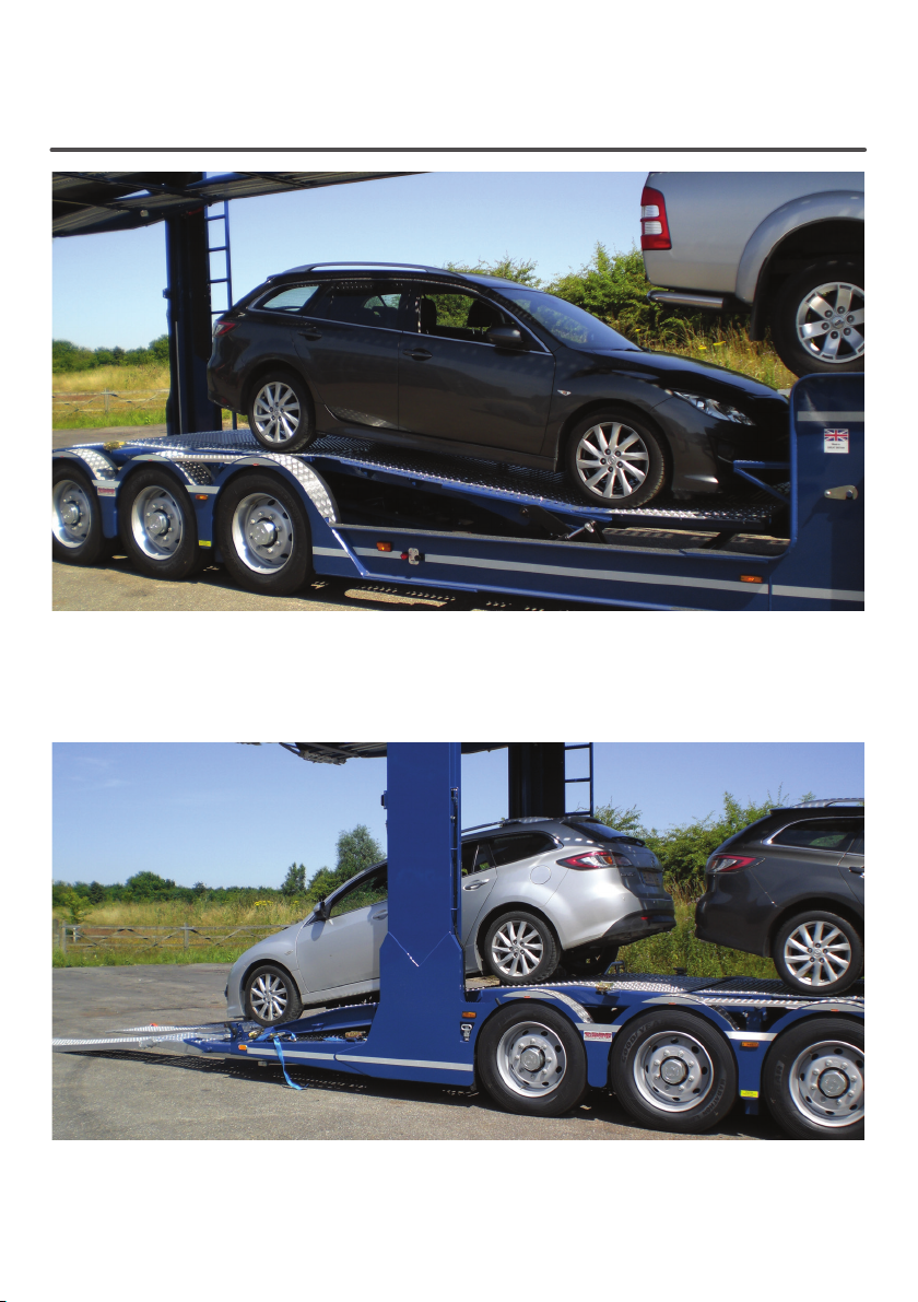
DRIVE THE LAST VEHICLE ONTO THE TRANSPORTER. PLACE A WHEEL CHOCK IN FRONT
OF EITHER THE FRONT OR REAR WHEELS AND SECURE THE VEHICLE TO
THE TRANSPORTER.
LOADING THE TRANSPORTER FINAL VEHICLE
20 21
RETURN THE MANUAL LOADING RAMPS INTO THE STOWAGE AND FULLY RETRACT
BOTH O/S AND N/S HYDRAULIC LOADING RAMPS. CHECK BOTH RAMPS ARE FULLY
CLOSED AND ARE LOCKING THE MANUAL RAMPS INTO THE STOWAGE RAMPS.
LOWER THE SWAN NECK FLAP AND THE REAR KICK UP RAMP THEN LOWER THE FRONT
AND REAR OF THE TOP DECK.
CHECK THE OVERALL HEIGHT OF THE VEHICLE AND THAT ALL VEHICLES AND
EQUIPMENT ARE SECURE.
LOADING THE TRANSPORTER
Table of contents
Other Transporter Farm Equipment manuals

Popular Farm Equipment manuals by other brands

Schaffert
Schaffert Rebounder Mounting instructions

Stocks AG
Stocks AG Fan Jet Pro Plus 65 Original Operating Manual and parts list

Cumberland
Cumberland Integra Feed-Link Installation and operation manual

BROWN
BROWN BDHP-1250 Owner's/operator's manual

Molon
Molon BCS operating instructions

Vaderstad
Vaderstad Rapid Series instructions


