TransTank TrailPro Deluxe Service manual

Manufacturer of The Safest Tanks in Motion
www.tti.com.au
TrailPro™ Deluxe
HANDBOOK
OPERATOR’S
with 6m boom and 30m Hose Reel

TTi’s TrailPro™ Deluxe HandBook
2Call 1800 816 277www.tti.com.au 2
Table of Contents
Introduction 3
Risk Assesment 4
Operating Instructions 5
Mixing and Filling 6
Calibration 6
Calibration Procedures 7
Spraying Guide 8
Spraying Consideration 9
After Season Care 10
STT Models 11
Spray Lance 12
Spare Parts List 13
Spare Parts List 14
Warranty 15
Warranty Limitations 16
Warranty Registration Card 17

TTi’s TrailPro™ Deluxe HandBook
3Call 1800 816 277www.tti.com.au 3
Introduction
Please read your operators handbook carefully before mounting and using your
SpotPro Deluxe sprayer. Keep your handbook in a safe place.
Congratulations on your purchase of a TTi SpotPro Sprayer which is complete and
ready to attach to an ATV. Ideally suited to farmers or spray contractors for weed
spraying, fence line spraying, spraying of drainage channels and around buildings
etc.
Your Safety
• When mounting to any vehicle ensure that you have read the Vehicle Owner’s
Manual and that you comply with all the weight restrictions as specified by the
vehicle manufacturer, as overloading can cause injury or death.
• To ensure your own safety and that of your employees if applicable you must
comply with all relevant environmental, work place health and safety legislation
and codes of practice.
• Select and wear appropriate Personal Protection Equipment in accordance with
the label of the product you intend using and your own safe work practices.
• Once the spraying operation has been completed, decontaminate the tank
and spray accessories. Dispose of tank rinsings in compliance with current
environmental, work place health and safety regulations.
• Personal Protection Equipment must still be worn while decontaminating your
sprayer as per warning at 3 above.
• Improper or careless use of this sprayer can cause serious injury. Minors should
never be allowed to use this sprayer. This sprayer should not be used when
bystanders or animals are in the area. This sprayer should never be used while
children are in the area.
• Never leave the sprayer unattended without turning off the engine and relieving
the line pressure, and flushing the sprayer of any harmful chemicals.
• You must be in good mental health to operate this sprayer and not be under the
influence of alcohol or any drugs that could impair your vision, physical strength,
dexterity, judgment, or other mental capacity

TTi’s TrailPro™ Deluxe HandBook
4Call 1800 816 277www.tti.com.au 4
Risk Assesment
Product Information Risk Assessment Sheet
TTi - TrailPro Sprayer
TASK HAZARDS RISK CONTROL MEASURES
Partially fill the tank
with water, start the
motor & test the spray
unit
Manual
handling; slips,
trips or falls;
petrol; fumes;
fingers jammed
Medium
Concentrate on task; follow safe
manual handling techniques:
• Don’t lift on your own if > 20kg;
• Bend knees & keep back
straight;
• Keep fingers clear;
• Keep unit at least 8m away
from overhead powerlines;
• Fire extinguisher nearby;
• Follow warning stickers on tanks;
• Wear PPE for petrol & fumes-
mask & gloves.
Check weather
conditions & select the
appropriate PPE to suit
the chemicals to be
used
Manual
handling; slips,
trips or falls
Low
• Put on PPE as per the chemical
requirements in the Material Safety
Data Sheet-coveralls, gloves, safety
footwear, glasses & respirator;
• Follow safe manual handling
techniques:-
• Don’t lift on your own if >20kg,
• Bend knees & keep back straight.
Mix chemicals
(if applicable)
&
fill spray tank
As above; spray
drift, chemical
spillage,
emission
of vapors or
flammability;
weather;
untrained
visitors
Medium
• As above;
• User trained in the state’s
chemical mixing &
administration course eg Chem.
Cert;
• Follow the relevant Environment
Protection Authority
requirements;
• Fire extinguisher present;
• Keep visitors away from the job
unless wearing full PPE.
Using spray unit
As above;
loss of load;
heat & cold;
noise; exceed
load limit of
vehicle; hose
entanglement;
exhaust fumes;
terrain & slopes;
run over by unit
High
• As above;
• Wear clothes to suit heat &
cold;
• Wear hearing protection if noise
> 85 dBa;
• follow the manufacturer’s safe
operation instruction for the
vehicle and the spray unit;
• Don’t overload - water weighs
1kg for every 1 litre;
• Secure load to vehicle;
• Keep hose tidy; put unit brakes
on.
Clean up,
maintenance &
storage
As above
Low
• As above;
• Continue to wear PPE for clean
up;
• Store unit in a dry, well
ventilated area.

TTi’s TrailPro™ Deluxe HandBook
5Call 1800 816 277www.tti.com.au 5
Operating Instructions
Check all hoses, connections and hose clamps to ensure that the unit has been
delivered to you without transportation loss or damage.
Before attempting any spraying with your new unit, operate it with water only to
familiarize yourself with its features and capabilities and to ensure that your sprayer
has arrived in a safe working condition. Please contact your dealer immediately
should anything appear to have been damaged.
Prepare the engine for use as per the engine manual supplies with your sprayer.
Ensure that the correct quantity and type of oil is used when filling the engine.
Start Up Procedure
• Prepare the engine for start as per the engine manual and pump manual.
• Add the spray solution to the tank (See “Mixing and Filling”).
• Ensure that the pressure regulator lever is in the BYPASS position and the pressure
adjusting knob is screwed out (anti-clockwise). Failure to do so will invalidate
pump warranty.
• Start the engine and allow it to warm up. Run the pump with the regulator lever
in the BYPASS position in order to discharge entrapped air from the system for at
least two minutes before changing the regulator lever to the PRESSURE position.
(Rotate clockwise)
• To set the correct spraying pressure, open the flow through the hand gun
(discharge solution back to tank) and turn the pressure regulator knob in a
clockwise direction until the required pressure is achieved. Spray nozzle pressure
will vary according to hose length, nozzle size, etc. When the hand gun is
released the increased pressure in the system will be automatically adjusted by
the pressure regulator valve and excess flow will be returned to the spray tank.

TTi’s TrailPro™ Deluxe HandBook
6Call 1800 816 277www.tti.com.au 6
Mixing and Filling
Sites for mixing and filling the sprayer should be carefully chosen to be away from any
risk of spillages draining into water courses or into environmentally sensitive areas.
Children and animals must always be kept way from mixing and filling operations.
The following steps are given as a guide for mixing and filling the sprayer.
• Read the product label and follow all directions carefully, taking special care
with regard to the order in which the products are added to the tank.
• Calibrate the sprayer according to recognized calibration method using water
only. Calibration must be done with the nozzle tip that has been selected for the
spraying task.
• Measure out the correct quantities of pesticides, using clean measuring jugs
used only for this purpose.
• Half fill the sprayer with clean water and then add the measured pesticide/
herbicide.
• Rinse out the measuring jug and empty container and pout all rinsings into the
spray tank. Agitate by stirring with a suitable round edged paddle.
• Top up the tank with water to the required level, ensure that the tank is not over-
filled and the outside is clean and dry before handling.
• Safely dispose of empty containers in compliance with current regulations
• Mixing sites must be well away from watercourses and other environmental
sensitive areas. Children and animals must be kept away.
Calibration
Accurate calibration is an essential of any spraying function as it ensures that
the chemical is applied at the rate intended on the product label. Application in
excess of the recommended rate is prohibited, can damage plants/foliage and is
uneconomical.
Calibration must always be carried out:
• When spraying for the first time with new spray equipment
• At the beginning of each season
• After changes of nozzle tips, spraying pressures or speed
• After every 100 hectares of spraying
When calibrating a sprayer, a minimum of coverall, gloves and boots must be worn.
A face shield and PVC apron may be included depending on the task and the
cleanliness of the sprayer.

TTi’s TrailPro™ Deluxe HandBook
7Call 1800 816 277www.tti.com.au 7
Calibration Procedures
Boom Sprayers Hydraulic Nozzles Example
Read the label
Spray VOLUME
Product Dose
Spray QUALITY
200 litres/hectare
50 litres/hectare
Medium
Measure TIME per
100 Metres
Measure time in seconds over land similar to
that to be sprayed 41.9 seconds
Calcute SPEED SPEED(km/h) = 360 divided by TIME (sec) 360/41.9 = 8.6km/h
Measure nozzle
SPACING Normally 0.5 metres (50cm) 0.5 metres
Measure TIME per
100 Metres
OUTPUT = VOLUME x SPEED x SPACE / 600
(L/min) (L/hec) (km/hr) (metre) 200 x 8.6 x 0.5 ÷600
Select NOZZLE
Refer to nozzle manufacturer data charts or
other sources and select the size and type
of nozzle that will produce the calculated
OUTPUT and required spray QUALITY
Now, check the calibration on the sprayer
Check nozzle
OUTPUT
With water, check outputs of 4 or more
nozzles using a calibrated jug or flow meter.
Check all nozzles are aligned correctly and
spray patterns are good
Average output = 41.9
litres/minute
Calibrate SPRAYER SPEED (km/h) = 360 divided by TIME (sec) 1.40 x 600 ÷0.5 ÷8.6
As the nozzle output and therefore the spray volume are less than target figures,
increase the pressure to, say 2.5 bar and repeat the calibration to achieve 200 litres
per hectare
Now, check the calibration on the sprayer
Nozzle Fitted 11004 - RED
Spray Volume 200 litres/hectare
Spray Pressure 2.5 bar
Spray Quality Medium
Forward Speed 8.6 km/h

TTi’s TrailPro™ Deluxe HandBook
8Call 1800 816 277www.tti.com.au 8
Spraying Guide
The following steps are given as a guide for spraying with your trailer unit.
• Before commencing spraying, plan the work effectively to reduce potential
contamination to a minimum.
• Wind Direction and speed must be taken into account. Avoid spraying on hot
and sunny days or when wind speed exceeds 6.5km/h
• Do not spray if the operator, bystanders, watercourses or any not targeted
vegetation appears to be in danger from spray drift contamination.
• Drift can be reduced by lower nozzle height, lower pressures or by fitting larger
nozzles.
• To commence spraying, squeeze trigger. Release the trigger to stop the spray –
the regulator will automatically allow spray solution to bypass through the return
line and back to the tank.
• Spray at a constant speed (as used during calibration) and shut off the hand
lance trigger or boom at the end of each swath or before changing direction.
• Work in parallel lines at the correct spacing when spraying large area – this is
better than moving the hand lance from side to side in a swinging movement
which causes damage by overdosing.

TTi’s TrailPro™ Deluxe HandBook
9Call 1800 816 277www.tti.com.au 9
Spraying Consideration
For effective spraying ensure you have taken the following factors into account.
1. Work Rates
• Speed of operation
• Water points or nurse tanks
• Rate of travel
• Swath width
• Spray volume applied
2. Wind and Drift
• Wind Speed
• Wind Direction
• Airspeed at boom height
• Avoid spraying on still warm days as convection currents may cause drift
in unpredictable directions.
• Optimum wind speeds are between 3km/h to 7km/h
• Wind direction and drift is controlled by;
• Reducing nozzle height
• Reducing pressure and using larger nozzle
• Fit low-drift nozzles producing larger droplets
3. Field Work (see diagram)
Swath marking and spraying
• Mark out to ensure proper pass matching
– use flags foam markers or tramlines
• Where large obstructions exist in the
middle of an area to be sprayed, mark
out and spray the area like a separate
headland
• The perimeter of the eld should be
sprayed rst. The width of two swaths will
give adequate turning space at the ends
of spray runs
• Never spray while turning
4. Speed
• Maintain a constant speed when spraying. Should you need to increase
your spraying speed, larger delivery nozzles must be fitted. Re-calibrate as
required
S G S D
OPERATORS HANDBOOK 9
SPRAYING CONSIDERATION
For effective spraying ensure you have taken the following factors into account
1. Work Rates
• Speed of operation
• Water points or nurse tanks
• Rate of travel
• Swath width
• Spray volume applied
2. Wind and drift
• Wind Speed
• Wind Direction
• Airspeed at boom height
Avoid spraying on still warm days as convection currents may cause drift in unpredictable
directions.
Optimum wind speeds are between 3km/h to 7 km/h
• Wind direction and drift is controlled by;:
• Reducing nozzle height
• Reducing pressure and using larger nozzles
• Fit low-drift nozzles producing larger droplets
3. Field Work (See diagram below)
Swath marking and spraying
• Mark out to ensure proper pass matching – use ags foam markers or tramlines
• Where large obstructions exist in the middle of an area to be sprayed, mark out and spray
the area like a separate headland.
• The perimeter of the eld should be sprayed rst. The width of two swaths will give
adequate turning space at the ends of spray runs.
• Never spray while turning.
4. Speed
Maintain a constant speed when spraying. Should you need
to increase your spraying speed, larger delivery nozzles
must be tted. Re-calibrate as required
OPERATOR HANDBOOK 8
CONSIDERATIONS WHEN SPRAYING
For effective spraying ensure you have taken the following factors into account
1. Work Rates
• Speed of operation
• Water points or nurse tanks
• Rate of travel
• Swath width
• Spray volume applied
2. Wind and drift
• Wind Speed
• Wind Direction
• Airspeed at boom height
Avoid spraying on still warm days as convection currents may cause drift in unpredictable
directions.
Optimum wind speeds are between 3km/h to 7 km/h
• Wind direction and drift is controlled by;:
• Reducing nozzle height
• Reducing pressure and using larger nozzles
• Fit low-drift nozzles producing larger droplets
3. Field Work (See diagram below)
Swath marking and spraying
• Mark out to ensure proper pass matching – use flags foam markers or tramlines
• Where large obstructions exist in the middle of an area to be sprayed, mark out and spray
the area like a separate headland.
• The perimeter of the field should be sprayed first. The width of two swaths will give
adequate turning space at the ends of spray runs.
• Never spray while turning.
4. Speed
Maintain a constant speed when spraying. Should you need to increase your spraying speed, larger
delivery nozzles must be fitted. Re-calibrate as required
www.tti.com.au
Call 1800 816 277
• After use, the sprayer must be thoroughly decontaminated including tank,
pump, hoses, boom and hand lance to avoid damage to crops from harmful
spray residue and to the sprayer from corrosion or abrasion.
• After spraying, flush the tank, hose, boom, and hand lance by running it with
clean water plus recommended cleaning fluid. It is best to clean sprayers in
the field or area just treated.
• The suction strainer attached to the pump suction line should be cleaned
periodically. Lift the strainer from the base of the tank and brush off with a soft
brush.
• Nozzle filters (if fitted), nozzle tips, nozzle caps and gaskets should be cleaned
by soaking in water, brushing with a nozzle brush and allowed to dry. Never blow
through nozzles with your mouth, not use wire or pins to clear any blockages.
• Unscrew the hand lance grip and remove the filter screen and clean in the
same way as described for the suction strainer. Ensure that the o-rings do not
become displaced during cleaning. Re-assemble the hand lance correctly.
• Aligning the filter screen in the handle body before the hand lance grip is
screwed back.
• Check tyre pressure.
• When storing your sprayer ensure that it is clean and dry and kept in a well
ventilated place.
9www.tti.com.au | Call 1800 816 277
TTi - Operators Handbook

TTi’s TrailPro™ Deluxe HandBook
10 Call 1800 816 277www.tti.com.au 10
After Season Care
NOTE: It is important that when cleaning the sprayer one wears proper safety
equipment. See your chemical or fertilizer package for this information.
• After spraying chemicals run water through the tank, pump, and all hose hookups.
If wettable powder dries out in the system it is very difficult to put back into
suspension and can cause malfunction, damage or injury.
• Disassemble the tips and rinse with water or cleaning solution (ie one appropriate
for the chemical sprayed).
• Clean the tip opening with a wooden toothpick. Never use wire or a hard object
that could distort the opening.
• Water rinse and dry the tips before storing.
Be sure to dispose of all unused chemicals or solutions in a proper and ecologically
sound manner.

TTi’s TrailPro™ Deluxe HandBook
11 Call 1800 816 277www.tti.com.au 11
STT Models
22 L/min Pump
Item Code Description
11 STA31 1 ¼” MBSP Poly Tank Fitting with Gasket
12 STAHS25 25mm Suction Hose
13 STAB031 1 ¼” Suction Filter Complete
14 4HP Honda Motor GC135
15 STAP31 Bertonini Pump & Gearbox 22l/m, 20Bar, - 20RT4
16 i) BE 80.3060.00.2 O’Ring 1.78 x 12.42mm
ii) BE 84.0521.00.2 90° Elbow Connector 19mm
iii) BE 82.0042.10.2 ¾” Flynut
17 STAHS19 19mm Suction Hose
18 aAR2452045 1 ¼” FBSP to 1” MBSP Reducer
18 bi) AR116420 1” X 20mm Elbow
ii) AR2002040 1” Flynut
iii) ARG10041 1” O’Ring
19 AIBFP30606 3/8” MBSP x 10mm Hose Barb - Brass
20 STAH10 10mm Spray Hose
21 STAP76 NPR20 Regulator - 20Ba
26 i) AR106525 1¼” x 25mm Straight
ii) ARG10051 1¼” O’Ring
iii) AR2002050 1¼” Flynut
34 L/min Pump
Item Code Description
11 STA31 1 ¼” MBSP Poly Tank Fitting with Gasket
12 STAHS25 25mm Suction Hose
13 STAB031 1 ¼” Suction Filter Complete
14 6.5HP Honda Motor GX160
15 STAP37 Bertonini Pump & Gearbox 34L/m, 40bAR,-PA330
16 i) BE 80.3200.00.2 O’Ring 2.62 x 22.22mm
ii) BE 84.0542.00.2 90° Elbow Connector 19mm
iii) BE 82.0049.10.2 Nut M34
17 STAHS25 25mm Suction Hose
18 i) AR2002050 1 ¼” Fly Nut
ii) ARG10051 1¼” O’Ring
iii) AR116525 1¼” x 25mm Elbow
19 AIBFP30606 3/8” MBSP x 10mm Hose Barb - Brass
20 STAH10 10mm Spray Hose
21 STAP78 NPR20 Regulator - 20Ba
26 i) AR106525 1¼” x 25mm Straight
ii) ARG10051 1¼” O’Ring
iii) AR2002050 1¼” Flynut

TTi’s TrailPro™ Deluxe HandBook
12 Call 1800 816 277www.tti.com.au 12
Spray Lance
S Lance
30.1903.8
29.17.02.26
23.602.34
23.602.29
29.507.10
29.1607.3
29.902.8
29.1003.24
23.1310.8
23.1603.14
23.1304.29
23.601.25
30.208.130
23.1003.16
29.801.40
29.1101.1
23.602.34
12 www.tti.com.au | Call 1800 816 277
TTi - Operators Handbook
TTi’s TrailPro™ Deluxe HandBook
13 Call 1800 816 277www.tti.com.au 13
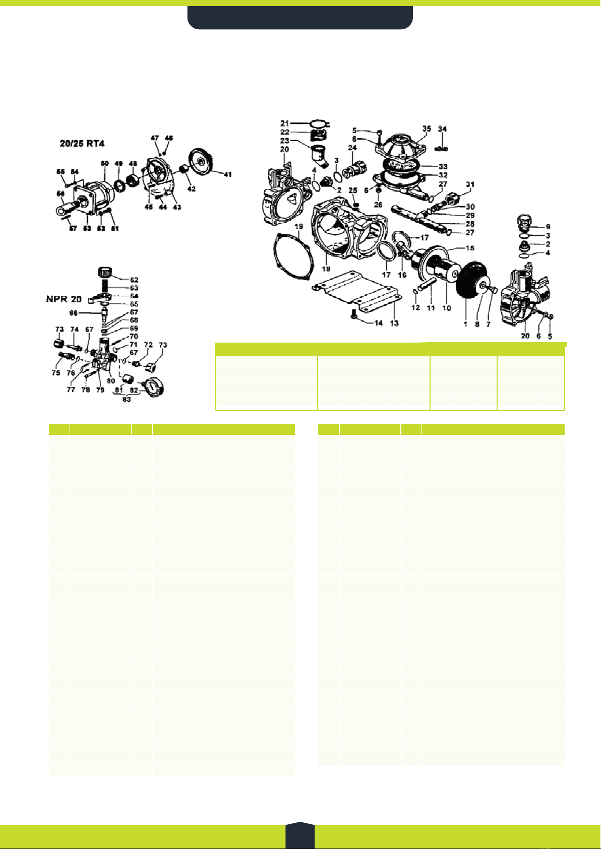
Spare Parts List
(Pump Series VF - STAP30) 22L/min
(PA 330 VF - STAP36) 34L/min
Pos Code Qty Description
194.0040.31.2 2Piston Diaphragm
194.0040.33.2 2Viton Piston Diaphragm (non stock)
294.9828.97.3 4Valve Assy
380.3219.00.2 4O-Ring 3.0 x 25
482.4154.00.2 4Gasket Dia. 30 x 24 x 1
586.2796.00.2 12 Screw M8 x 40 UNI5931
684.3685.00.2 16 Washer Dia. 8.4 x 15 x 1.5
794.0048.43.2 2Diaphragm Locking Bolt
894.0036.32.2 2Disk
994.0091.98.2 2Outlet Valve Cap
10 94.0017.08.2 2Piston Dia. 42 (20 series)
10 94.0016.08.2 2Piston Dia. 48 (25 series)
11 85.2004.00.2 2Piston Pin
12 80.0003.00.2 4Ring Dia. 10
13 94.0022.61.2 1Mounting Rail
14 86.2059.00.2 4Screw M6 x 14 UNI5739
15 94.0007.01.2 2Piston Sleeve Dia. 42 (20 series)
15 94.0005.01.2 Piston Sleeve Dia. 48 (25 series)
16 94.0008.09.2 2Conrod
17 94.0047.76.2 2Conrod Ring
18 94.0001.09.2 1Crankcase
19 94.0080.72.2 1Crankcase Cover Gasket
20 94.0002.09.2 2Pump Head
21 81.7537.00.2 1Clamp
22 94.0044.31.2 1Oil Filter Cap
23 94.0043.32.2 1Oil Filter
24 94.0090.98.2 2Inlet Valve Cap
25 94.0075.66.2 1Cap
26 81.4575.00.2 4Nut MB UNI5588
27 80.3181.00.2 4O-Ring 2.62 x 15.54
28 94.0014.32.2 1Inlet Manifold
29 80.3060.00.2 1O-Ring 1.78 x 12.42
30 84.0521.00.2 190° Elbow Connector Dia. 20
31 82.0042.10.2 1Wing Nut G. 3/4
32 94.0004.09.2 1Damper Body
33 94.0041.31.2 1Damper Diaphragm
33 94.0041.33.2 1Viton Damper Diaphragm
34 86.1605.00.2 1Air Valve
35 94.0003.09.2 1Damper Cover
Pos Code Qty Description
41 81.2837.00.2 1Ball Bearing Dia. 35 x 62 x 14
42 80.2178.10.2 1Oi Seal Dia. 40 x 52 x 7
43 94.0216.09.2 1Bearing Housing (VF)
44 86.2168.00.2 4Screw M6 x 22 UNI5931
45 94.0029.26.2 1Crankshaft VF
46 81.4525.00.2 3Dado M5 Uni5588
47 84.3542.00.2 2Rosetta D.5, 3 x 10 x 1
48 81.2631.00.2 1Cuscinetto Stere
49 80.2117.00.2 1Anello Radiale
50 80.3210.64.2 1Anello Or 2,62 x 75, 87
51 86.2566.00.2 4Vite Te 5/16” - 24 unf L=3/4”
51 86.2622.00.2 4Vite Te M8 x 22 Uni5739 (Honda G100)
52 84.3685.00.2 4Rosetta D.8, 2 x 15 x 1,5
53 94.0210.09.2 1Flangia Motori Termici (Rt4”)
54 84.3560.00.2 3Rosetta D.5, 5 x 15 x 1,6
55 86.1935.10.2 2Vite Te M5 x 25 Uni 5737
56 94.0211.42.2 1Pignone Z=10 (Sae 3/4”)
56 94.0228.42.2 1Pignone Z=10 (Honda G100-s)
56 94.0218.42.2 1Pignone Z=10 (Honda G100-q)
57 80.6436.00.2 1Linguetta 4, 75 x 5 x 30
57 80.6445.00.2 1Linguetta 5 x 5 x 30 (Honda G100-s)
62 94.0203.32.2 1Knob
63 94.0073.48.2 1Spring
64 94.0202.32.2 1Lever
65 80.3199.00.2 1O-Ring 2.62 x 21.89
66 94.0204.32.2 1Poppet
67 80.3174.00.2 4O-Ring 2.62 x 9.92
68 05.0068.51.2 1Seat
69 80.3056.00.2 1O-Ring 1.78 x 8.73
70 85.1045.00.2 1Pin Dia, 3 x 30
71 80.3217.00.2 1O-Ring 3.0 x 14
72 94.0201.32.2 1Pressure Regulator Plug
73 82.0015.00.2 2Wing Nut G. 1/2
74 84.1528.00.2 1Outlet Conenctor Dia. 10
75 84.1551.00.2 1Return Connector Dia. 13
76 80.3178.00.2 1O-Ring 2.62 x 13.1
77 94.0206.49.2 1Quick Release Pin
78 86.1743.90.2 2Screw M5 x 45 UNI5931
Spare Kits
TTi Part No. STAP101 STAP102 STAP103
Kit Part No. 94.9881.97.3 94.9870.97.3 94.9871.97.3
Kit Description Pump
Seals Kit VF
Valves
Assy
BUNA-N
Diaphragms
Position No. 42 27 3 4 19 234127 4
S L
(Pump Series VF - STAP30) 22L/min
(PA 330 VF - STAP36) 34L/min
S P L
Pos Code Qty Description
194.0040.31.2 2Piston Diaphragm
194.0040.33.2 2Viton Piston Diaphragm (non stock)
294.9828.97.3 4Valve Assy
380.3219.00.2 4O-Ring 3.0 x 25
482.4154.00.2 4Gasket Dia. 30 x 24 x 1
586.2796.00.2 12 Screw M8 x 40 UNI5931
684.3685.00.2 16 Washer Dia. 8.4 x 15 x 1.5
794.0048.43.2 2Diaphragm Locking Bolt
894.0036.32.2 2Disk
994.0091.98.2 2Outlet Valve Cap
10 94.0017.08.2 2Piston Dia. 42 (20 series)
10 94.0016.08.2 2Piston Dia. 48 (25 series)
11 85.2004.00.2 2Piston Pin
12 80.0003.00.2 4Ring Dia. 10
13 94.0022.61.2 1Mounting Rail
14 86.2059.00.2 4Screw M6 x 14 UNI5739
15 94.0007.01.2 2Piston Sleeve Dia. 42 (20 series)
15 94.0005.01.2 Piston Sleeve Dia. 48 (25 series)
16 94.0008.09.2 2Conrod
17 94.0047.76.2 2Conrod Ring
18 94.0001.09.2 1Crankcase
19 94.0080.72.2 1Crankcase Cover Gasket
20 94.0002.09.2 2Pump Head
21 81.7537.00.2 1Clamp
22 94.0044.31.2 1Oil Filter Cap
23 94.0043.32.2 1Oil Filter
24 94.0090.98.2 2Inlet Valve Cap
25 94.0075.66.2 1Cap
26 81.4575.00.2 4Nut MB UNI5588
27 80.3181.00.2 4O-Ring 2.62 x 15.54
28 94.0014.32.2 1Inlet Manifold
29 80.3060.00.2 1O-Ring 1.78 x 12.42
30 84.0521.00.2 190° Elbow Connector Dia. 20
31 82.0042.10.2 1Wing Nut G. 3/4
32 94.0004.09.2 1Damper Body
33 94.0041.31.2 1Damper Diaphragm
33 94.0041.33.2 1Viton Damper Diaphragm
34 86.1605.00.2 1Air Valve
35 94.0003.09.2 1Damper Cover
36 81.2531.00.2 1Needle Bearing DHK 1312
37 94.0026.32.2 1Crankshaft Spacer
38 81.2688.00.2 1Needle Bearing DHK 2520
39 94.0027.32.2 1Spacer
40 80.1264.00.2 1Ring Dia. 35
Pos Code Qty Description
41 81.2837.00.2 1Ball Bearing Dia. 35 x 62 x 14
42 80.2178.10.2 1Oi Seal Dia. 40 x 52 x 7
43 94.0216.09.2 1Bearing Housing (VF)
44 86.2168.00.2 4Screw M6 x 22 UNI5931
45 94.0029.26.2 1Crankshaft VF
46 81.4525.00.2 3Dado M5 Uni5588
47 84.3542.00.2 2Rosetta D.5, 3 x 10 x 1
48 81.2631.00.2 1Cuscinetto Stere
49 80.2117.00.2 1Anello Radiale
50 80.3210.64.2 1Anello Or 2,62 x 75, 87
51 86.2566.00.2 4Vite Te 5/16” - 24 unf L=3/4”
51 86.2622.00.2 4Vite Te M8 x 22 Uni5739 (Honda G100)
52 84.3685.00.2 4Rosetta D.8, 2 x 15 x 1,5
53 94.0210.09.2 1Flangia Motori Termici (Rt4”)
54 84.3560.00.2 3Rosetta D.5, 5 x 15 x 1,6
55 86.1935.10.2 2Vite Te M5 x 25 Uni 5737
56 94.0211.42.2 1Pignone Z=10 (Sae 3/4”)
56 94.0228.42.2 1Pignone Z=10 (Honda G100-s)
56 94.0218.42.2 1Pignone Z=10 (Honda G100-q)
57 80.6436.00.2 1Linguetta 4, 75 x 5 x 30
57 80.6445.00.2 1Linguetta 5 x 5 x 30 (Honda G100-s)
62 94.0203.32.2 1Knob
63 94.0073.48.2 1Spring
64 94.0202.32.2 1Lever
65 80.3199.00.2 1O-Ring 2.62 x 21.89
66 94.0204.32.2 1Poppet
67 80.3174.00.2 4O-Ring 2.62 x 9.92
68 05.0068.51.2 1Seat
69 80.3056.00.2 1O-Ring 1.78 x 8.73
70 85.1045.00.2 1Pin Dia, 3 x 30
71 80.3217.00.2 1O-Ring 3.0 x 14
72 94.0201.32.2 1Pressure Regulator Plug
73 82.0015.00.2 2Wing Nut G. 1/2
74 84.1528.00.2 1Outlet Conenctor Dia. 10
75 84.1551.00.2 1Return Connector Dia. 13
76 80.3178.00.2 1O-Ring 2.62 x 13.1
77 94.0206.49.2 1Quick Release Pin
78 86.1743.90.2 2Screw M5 x 45 UNI5931
79 84.3542.00.2 2Washer Dia. 5.3 x 10 x 1
80 94.0200.32.2 1Pressure Regulator Body
81 94.0207.32.2 1Nipples G. 1/2 - G. 1/4
82 83.0010.002 1Pressure Gauge
83 94.9849.97.3 1Pressure Gauge Kit
Spare Kits
TTi Part No. STAP101 STAP102 STAP103
Kit Part No. 94.9881.97.3 94.9870.97.3 94.9871.97.3
Kit Description Pump
Seals Kit VF
Valves
Assy
BUNA-N
Diaphragms
Position No. 42 27 3 4 19 234127 4
Quantity Incl. 14441444241
13www.tti.com.au | Call 1800 816 277
TTi - Operators Handbook

TTi’s TrailPro™ Deluxe HandBook
14 Call 1800 816 277www.tti.com.au 14
Spare Parts List
Karin STAP77 (15bar) + STAP78 (40bar)
Karin STAP77 (15bar) + STAP78 (40bar)
STING - STAP79 (15bar) + STAP80 (40bar)
S P L
Pos Code Qty Description
124.0310.32.2 1Valve Housing
283.0080.00.2 1Pressure Gauge 0-100 Bar
283.0010.00.2 1Pressure Gauge 0-24 Bar
380.3060.00.2 1O-Ring 1.78 x 12.42
454.0521.00.2 190° Elbow Connector Dia. 20
582.0042.10.2 1Wing Nut G. 3/4
684.5544.10.2 1Left Tap G.3/8 - G. 1/2
784.1544.00.2 2Outlet Straight Port D. 10
882.0010.00.2 2Wing Nut G. 1/2
984.5544.00.2 1Right Tap G. 3/8 - G. 1/2
10 85.2585.00.2 1Cap G. 3/8
11 84.3585.00.2 2Washer Dia. 6.4 x 12.5 x 1.6
12 86.2426.00.2 2Screw M6 x 60 UNI5737
13 84.4525.00.2 4Nut M5 UNI5588
14 80.3218.00.2 1O-Ring 3.0 x 22
15 80.3059.00.2 1O-Ring D. 1.78 x 11.11
16 24.0320.51.2 1Valve Seat
17 86.1841.50.2 1Screw M4 x 12
18 24.0319.51.2 1Poppet
19 24.0313.36.2 1HPS Diaphragm
20 84.3539.00.2 4Washer Dia. 5.3 x 10 x 1
21 86.1944.20.2 4Screw M5 x 50
22 24.0311.32.2 1Flange
23 80.3075.00.2 1O-Ring
24 80.3175.00.2 1O-Ring 2.62 x 10.78
25 85.1148.00.2 1Pin
26 24.0314.53.2 1Guiding Piston
27 24.0312.32.2 1Lever
28 24.0316.48.2 1Spring 40 Bar
28 24.0550.18.2 1Spring 15 Bar
29 24.0321.32.2 1Knob
Pos Code Qty Description
124.0310.32.2 1Valve Housing
283.0080.00.2 1Pressure Gauge 0-100 Bar
283.0010.00.2 1Pressure Gauge 0-24 Bar
380.3060.00.2 1O-Ring 1.78 x 12.42
454.0521.00.2 190° Elbow Connector Dia. 20
582.0042.10.2 1Wing Nut G. 3/4
684.5544.10.2 1Left Tap G.3/8 - G. 1/2
784.1544.00.2 2,3 Outlet Straight Port D. 10
882.0010.00.2 2,3 Wing Nut G. 1/2
984.5544.00.2 1,2 Right Tap G. 3/8 - G. 1/2
10 85.2585.00.2 1,2 Cap G. 3/8
11 80.3213.00.2 1C-Ring 3.0 x 22
12 80.3182.00.2 1C-Ring 2.62 x 17.13
13 26.0220.18.2 1Valve Seat
14 86.1934.80.2 1Screw M5 x 16 UNI5933 Inox
15 26.0201.18.2 1Ceramic Poppet
16 26.0189.36.2 1HPS Diaphragm
17 26.0203.32.2 1Diaphragm Holder Piston
18 24.0301.32.2 1Flange
19 80.3208.20.2 1O-Ring 2.62 x 34.6
20 80.3181.20.2 4O-Ring 2.62 x 15.88
21 24.0302.53.2 4Guiding Piston
22 24.0303.32.2 1Lever
23 85.1161.00.2 1Pin Dia. 4 x 45.5
24 26.0217.48.2 1Spring (15 Bar)
24 26.0212.48.2 1Spring (40 Bar)
25 24.0304.61.2 1Shim
26 24.0304.32.2 1Knob
27 24.0306.49.2 1Spring
28 86.2428.00.2 1Screw T.C.E.I. M6 x 65 UNI5931
29 24.0307.32.2 1Cap
30 81.4542.00.2 4Nut M6 UNI5588
31 84.3585.00.2 6Washer Dia. 6.4 x 12.5 x 1.6
32 86.2426.00.2 6Screw M6 x 60 UNI5737
Spare Kits
TTi Part No. STAP133
Kit Part No. 25.9963.97.3
Kit Description Karin Kit
Position No. 314 15 16 18 19 23 24
Quantity Incl. 1 1 1 1 1 1 1 1
Spare Kits
TTi Part No. STAP134
Kit Part No. 25.9964.97.3
Kit Description Sting Kit
Position No. 311 12 13 15 16 19 20
Quantity Incl. 1 1 1 1 1 1 1 1
14
www.tti.com.au |
Call 1800 816 277
TTi - Operators Handbook
Pos Code Qty Description
124.0310.32.2 1Valve Housing
283.0080.00.2 1Pressure Gauge 0-100 Bar
283.0010.00.2 1Pressure Gauge 0-24 Bar
380.3060.00.2 1O-Ring 1.78 x 12.42
454.0521.00.2 190° Elbow Connector Dia. 20
582.0042.10.2 1Wing Nut G. 3/4
684.5544.10.2 1Left Tap G.3/8 - G. 1/2
784.1544.00.2 2Outlet Straight Port D. 10
882.0010.00.2 2Wing Nut G. 1/2
984.5544.00.2 1Right Tap G. 3/8 - G. 1/2
10 85.2585.00.2 1Cap G. 3/8
11 84.3585.00.2 2Washer Dia. 6.4 x 12.5 x 1.6
12 86.2426.00.2 2Screw M6 x 60 UNI5737
13 84.4525.00.2 4Nut M5 UNI5588
14 80.3218.00.2 1O-Ring 3.0 x 22
15 80.3059.00.2 1O-Ring D. 1.78 x 11.11
16 24.0320.51.2 1Valve Seat
17 86.1841.50.2 1Screw M4 x 12
18 24.0319.51.2 1Poppet
19 24.0313.36.2 1HPS Diaphragm
20 84.3539.00.2 4Washer Dia. 5.3 x 10 x 1
21 86.1944.20.2 4Screw M5 x 50
22 24.0311.32.2 1Flange
23 80.3075.00.2 1O-Ring
24 80.3175.00.2 1O-Ring 2.62 x 10.78
25 85.1148.00.2 1Pin
26 24.0314.53.2 1Guiding Piston
27 24.0312.32.2 1Lever
28 24.0316.48.2 1Spring 40 Bar
28 24.0550.18.2 1Spring 15 Bar
29 24.0321.32.2 1Knob
Spare Kits
TTi Part No. STAP133
Kit Part No. 25.9963.97.3
Kit Description Karin Kit
Position No. 314 15 16 18 19 23 24
Quantity Incl. 1 1 1 1 1 1 1 1
STING - STAP79 (15bar) + STAP80 (40bar)
Karin STAP77 (15bar) + STAP78 (40bar)
STING - STAP79 (15bar) + STAP80 (40bar)
S P L
Pos Code Qty Description
124.0310.32.2 1Valve Housing
283.0080.00.2 1Pressure Gauge 0-100 Bar
283.0010.00.2 1Pressure Gauge 0-24 Bar
380.3060.00.2 1O-Ring 1.78 x 12.42
454.0521.00.2 190° Elbow Connector Dia. 20
582.0042.10.2 1Wing Nut G. 3/4
684.5544.10.2 1Left Tap G.3/8 - G. 1/2
784.1544.00.2 2Outlet Straight Port D. 10
882.0010.00.2 2Wing Nut G. 1/2
984.5544.00.2 1Right Tap G. 3/8 - G. 1/2
10 85.2585.00.2 1Cap G. 3/8
11 84.3585.00.2 2Washer Dia. 6.4 x 12.5 x 1.6
12 86.2426.00.2 2Screw M6 x 60 UNI5737
13 84.4525.00.2 4Nut M5 UNI5588
14 80.3218.00.2 1O-Ring 3.0 x 22
15 80.3059.00.2 1O-Ring D. 1.78 x 11.11
16 24.0320.51.2 1Valve Seat
17 86.1841.50.2 1Screw M4 x 12
18 24.0319.51.2 1Poppet
19 24.0313.36.2 1HPS Diaphragm
20 84.3539.00.2 4Washer Dia. 5.3 x 10 x 1
21 86.1944.20.2 4Screw M5 x 50
22 24.0311.32.2 1Flange
23 80.3075.00.2 1O-Ring
24 80.3175.00.2 1O-Ring 2.62 x 10.78
25 85.1148.00.2 1Pin
26 24.0314.53.2 1Guiding Piston
27 24.0312.32.2 1Lever
28 24.0316.48.2 1Spring 40 Bar
28 24.0550.18.2 1Spring 15 Bar
29 24.0321.32.2 1Knob
Pos Code Qty Description
124.0310.32.2 1Valve Housing
283.0080.00.2 1Pressure Gauge 0-100 Bar
283.0010.00.2 1Pressure Gauge 0-24 Bar
380.3060.00.2 1O-Ring 1.78 x 12.42
454.0521.00.2 190° Elbow Connector Dia. 20
582.0042.10.2 1Wing Nut G. 3/4
684.5544.10.2 1Left Tap G.3/8 - G. 1/2
784.1544.00.2 2,3 Outlet Straight Port D. 10
882.0010.00.2 2,3 Wing Nut G. 1/2
984.5544.00.2 1,2 Right Tap G. 3/8 - G. 1/2
10 85.2585.00.2 1,2 Cap G. 3/8
11 80.3213.00.2 1C-Ring 3.0 x 22
12 80.3182.00.2 1C-Ring 2.62 x 17.13
13 26.0220.18.2 1Valve Seat
14 86.1934.80.2 1Screw M5 x 16 UNI5933 Inox
15 26.0201.18.2 1Ceramic Poppet
16 26.0189.36.2 1HPS Diaphragm
17 26.0203.32.2 1Diaphragm Holder Piston
18 24.0301.32.2 1Flange
19 80.3208.20.2 1O-Ring 2.62 x 34.6
20 80.3181.20.2 4O-Ring 2.62 x 15.88
21 24.0302.53.2 4Guiding Piston
22 24.0303.32.2 1Lever
23 85.1161.00.2 1Pin Dia. 4 x 45.5
24 26.0217.48.2 1Spring (15 Bar)
24 26.0212.48.2 1Spring (40 Bar)
25 24.0304.61.2 1Shim
26 24.0304.32.2 1Knob
27 24.0306.49.2 1Spring
28 86.2428.00.2 1Screw T.C.E.I. M6 x 65 UNI5931
29 24.0307.32.2 1Cap
30 81.4542.00.2 4Nut M6 UNI5588
31 84.3585.00.2 6Washer Dia. 6.4 x 12.5 x 1.6
32 86.2426.00.2 6Screw M6 x 60 UNI5737
Spare Kits
TTi Part No. STAP133
Kit Part No. 25.9963.97.3
Kit Description Karin Kit
Position No. 314 15 16 18 19 23 24
Quantity Incl. 1 1 1 1 1 1 1 1
Spare Kits
TTi Part No. STAP134
Kit Part No. 25.9964.97.3
Kit Description Sting Kit
Position No. 311 12 13 15 16 19 20
Quantity Incl. 1 1 1 1 1 1 1 1
14 www.tti.com.au | Call 1800 816 277
TTi - Operators Handbook
Pos Code Qty Description
124.0310.32.2 1Valve Housing
283.0080.00.2 1Pressure Gauge 0-100 Bar
283.0010.00.2 1Pressure Gauge 0-24 Bar
380.3060.00.2 1O-Ring 1.78 x 12.42
454.0521.00.2 190° Elbow Connector Dia. 20
582.0042.10.2 1Wing Nut G. 3/4
684.5544.10.2 1Left Tap G.3/8 - G. 1/2
784.1544.00.2 2,3 Outlet Straight Port D. 10
882.0010.00.2 2,3 Wing Nut G. 1/2
984.5544.00.2 1,2 Right Tap G. 3/8 - G. 1/2
10 85.2585.00.2 1,2 Cap G. 3/8
11 80.3213.00.2 1C-Ring 3.0 x 22
12 80.3182.00.2 1C-Ring 2.62 x 17.13
13 26.0220.18.2 1Valve Seat
14 86.1934.80.2 1Screw M5 x 16 UNI5933 Inox
15 26.0201.18.2 1Ceramic Poppet
16 26.0189.36.2 1HPS Diaphragm
17 26.0203.32.2 1Diaphragm Holder Piston
18 24.0301.32.2 1Flange
19 80.3208.20.2 1O-Ring 2.62 x 34.6
20 80.3181.20.2 4O-Ring 2.62 x 15.88
21 24.0302.53.2 4Guiding Piston
22 24.0303.32.2 1Lever
23 85.1161.00.2 1Pin Dia. 4 x 45.5
24 26.0217.48.2 1Spring (15 Bar)
24 26.0212.48.2 1Spring (40 Bar)
25 24.0304.61.2 1Shim
26 24.0304.32.2 1Knob
27 24.0306.49.2 1Spring
28 86.2428.00.2 1Screw T.C.E.I. M6 x 65 UNI5931
29 24.0307.32.2 1Cap
30 81.4542.00.2 4Nut M6 UNI5588
31 84.3585.00.2 6Washer Dia. 6.4 x 12.5 x 1.6
32 86.2426.00.2 6Screw M6 x 60 UNI5737
Spare Kits
TTi Part No. STAP134
Kit Part No. 25.9964.97.3
Kit Description Sting Kit
Position No. 311 12 13 15 16 19 20
Quantity Incl. 1 1 1 1 1 1 1 1

TTi’s TrailPro™ Deluxe HandBook
15 Call 1800 816 277www.tti.com.au 15
Warranty
Warranty Policy
Your TrailPro is guaranteed free from defect in materials, workmanship or manufacture
for 12 months from the date of purchase. Any parts which appear to us to be
defective either in material or workmanship will be replaced or repaired at no cost
to the purchaser, subject to the following conditions:
1. The registration card enclosed in this handbook must be returned to us within 7
days of purchase.
2. The guidelines in this handbook have been adhered to in every respect.
3. In the unlikely event of sprayer failure this should be reported to your dealer who
will act on your behalf to resolve the issue to your satisfaction.
4. Any defective parts will be returned by your dealer within 7 days of failure,
together with a report describing the failure and conditions in which the failure
occurred.
5. The following are specifically excluded from the terms of warranty:
• Fair wear and tear to pump moving parts and diaphragms
• Fair wear and tear to nozzles and nozzle bodies
• Damage caused by neglect or lack of lubrication
• Damage caused by misuse or abuse
• Damage caused while the sprayer is in transit

TTi’s TrailPro™ Deluxe HandBook
16 Call 1800 816 277www.tti.com.au 16
Warranty Limitations
a] There is no other express warranty. Any warranty that may be implied from this
purchase including merchantibility and finess for a particular purpose is hereby
limited to the duration of this warranty and to the extent permitted by law. Any and
all implied warranties are excluded.
b] TTI will not be liable for any incidental, consequential or special damages and/
or expenses in connection with the purchase or use of this equipment, to the extent
permitted by law.
c] Only the warranty expressed in this limited warranty shall apply and no dealer,
distributor, or individual is authorized to amend, modify, or extend this warranty
in any way. Accordingly, additional statements, whether oral or written, do not
constitute warranties by TTi, and should not be relied upon.
Whilst every care has been taken in the preparation of these instructions, no liabilities
can be accepted with regard to errors or omissions. Product specifications are
subject to change in line with our commitment to continuous improvement.

TTi’s TrailPro™ Deluxe HandBook
17 Call 1800 816 277www.tti.com.au 17
Warranty Registration Card
To validate your warranty, please complete registration on-line at:
www.tti.com.au/warranty-registration
Alternatively if you are unable to register on-line fill in all the details below, copy
I have read and understood the instructions in this booklet.
[located on side of tank]
Model:
Serial Number:
Date Purchased:
Purchaser’s Name:
Post code:
Purchaser’s Address:
Phone #: Mobile #:
Email Address:
Purchaser’s Signature:
/.
/.
/.
/.


www.tti.com.au
1800 816 277
sales@tti.com.au
PO Box 137, Nathalia, VIC, 3638
Murray Valley Hwy, Nathalia, VIC 3638
Table of contents
Other TransTank Utility Vehicle manuals


Popular Utility Vehicle manuals by other brands


Cub Cadet
Cub Cadet M465 Operator's manual

Polaris
Polaris BRUTUS HD Operator's handbook

Taylor-Dunn
Taylor-Dunn B0-248-48AC Operation, t roubleshooting and replacement parts manual

Craftsman
Craftsman ZTS 7500 Operator's manual

Textron Specialized Vehicles
Textron Specialized Vehicles Cushman Shuttle 4 ELiTE 2020 owner's manual

Polaris
Polaris RANGER XP 900 2013 owner's manual


