Trapeze Ranger 7-RNGR-04X Manual

Hardware Installation Guide
Ranger 7-RNGR-04X
Ver 5.8

Adobe Reader® is a registered trademark/trademark of Adobe Systems Incorporated in the
United States and other countries. Microsoft® Windows® and Microsoft® Word are registered
trademarks/trademarks of Microsoft Corporation in the United States and/in other countries.
© 2013 Trapeze Software ULC, its subsidiaries and affiliates (collectively “TSU”). All rights
reserved. TSU Proprietary and Confidential: Information contained in this document is propri-
etary to TSU, and may be used or disclosed only with written permission from TSU. This guide,
or any part thereof, may not be reproduced without the prior written permission of TSU. The
recipient acknowledges and agrees that disclosure of this document to recipient, and its use,
are subject to the terms and conditions specified in their relevant software license Agreement,
software maintenance
agreement, and/or non-disclosure agreement (“Governing Agreement”) under which this doc-
ument was disclosed. This document is for internal use only in conjunction with TSU products.
This document may not be modified in any way. Except as may be provided in the Governing
Agreement, TSU and its affiliates, subsidiaries, officers, directors, employees and agents pro-
vide the information contained in this manual on an “as-is” basis and do not make any express
or implied warranties or representations with respect to such information including, without lim-
itation, warranties as to non-infringement,
reliability, fitness for a particular purpose, usefulness, completeness, accuracy or currentness.
TSU shall not in any circumstances be liable to any person for any special, incidental, indirect
or consequential damages, including without limitation, damages resulting from use of or reli-
ance on information presented herein, or loss of profits or revenues or costs of replacement
goods, even if informed in advance of the possibility of such damages.
TSU reserves the right, to be exercised at its sole discretion and without notice, to change,
modify or adapt the contents of this edition in order to accurately reflect any future upgrades
to the TSU proprietary software and/or hardware. In the event of such changes, TSU expects,
but does not represent or guarantee, that this current edition will continue to remain reason-
ably accurate insofar as it describes the basic functions of the TSU proprietary software and/or
hardware. Furthermore, based on your system settings, certain functionality, such as applica-
tion screens, may not function exactly as shown or described in this guide.


Safety & After-Market Equipment............................1
Qualied Installer....................................................2
Introduction ............................................................3
Before You Begin .....................................................4
Cautions................................................................. 4
Ranger Overview .......................................................... 5
Parts List..................................................................6
Supplied................................................................. 6
Supplied (Optional) ................................................. 6
Not Supplied........................................................... 6
Mounting Locations .................................................7
Placement .............................................................. 7
Ranger Mounting Examples .....................................8
Examples of Suitable Mounting Locations .................. 8
Installing The Ranger Cover Plate ...........................9
Wiring - Ranger Back View ......................................12
Connection Points....................................................14
1) Splicing.............................................................. 14
2) Power ................................................................ 14
3) Ground .............................................................. 14
4) Switched Ignition Power ...................................... 14
5) VSS (Vehicle Speed Sensor for Odometer Pulses)... 15
6) Emergency Switch (optional)................................ 16
Ranger V1/V2 Upgrades ..........................................17
Cabling.....................................................................18
1) Routing.............................................................. 18
2) Strain Relief........................................................ 18
3) Labeling ............................................................. 18
4) Connection Types................................................ 19
5) Wire Types ......................................................... 20
6) Electrical Measurements ...................................... 20
TABLE OF CONTENTS

Antennas..................................................................21
1) Internal Antennas ............................................... 21
2) External Antennas............................................... 21
3) Cable Routing..................................................... 21
4) Connectors......................................................... 22
Ranger Specs 7-RNGR-04X .....................................23
General Description................................................. 23
Standard Features................................................... 23
Compliance and Testing........................................... 24
Optional Features.................................................... 24
KeySpecications ................................................... 24
Appendix A - Conformity..........................................26
1) FCC Class B Part 15............................................. 26
2) IEC 60950 3rd Edition (2000) Safety of Information
Technology Equipment ........................................ 28
3) ISO 7637-1 Load Dump Transient......................... 27
4) MIL STD 810F: General Vibration.......................... 28
5) MIL STD 810F: Shock Test ................................... 28
6) IEC 60529 - IP54 ................................................ 28
Appendix B - RF Radiation Specs .............................29
RF Exposure ........................................................... 30
Appendix C - Approvals............................................30
1) CDMA/EVDO....................................................... 30
2) GSM/HSPA.......................................................... 30
3) WIFI/Bluetooth Only ........................................... 30
TABLE OF CONTENTS

1
TRADE SECRET. Trapeze Proprietary and Confidential. © 2013 Trapeze Software ULC, its subsidiaries and affiliates. All rights reserved.
The use of after-market equipment in motor vehicles can compromise a vehicle’s safe-
ty-related design characteristics, including but not limited to:
• Airbags, including but not limited to potential obstruction of airbag deployment;
• Passenger compartment, including but not limited to potential for ergonomic
problems, physical obstacles, etc.; and
• Trunk/gas tank protection, including but not limited to the potential for
trunk-mounted equipment to exacerbate tank vulnerability in a rear collision.
This product is to be installed by qualified installation personnel only. The installer must
be trained in industry best practices for this type of installation. The training would
include but not be limited to:
1. The appropriate methods for installing cables such that:
• The operation of the vehicle is not interfered with.
• The installation process does not damage or interfere with other vehicle compo-
nents and/or systems.
• Wiring is kept clear of sharp objects, sources of heat and any other hazard that
could damage the cable or wire.
• Wiring is secured such that it does not cause damage to other equipment, itself,
or interfere with the operation of other systems and devices.
• Wiring through bulkheads is performed such that wiring does not chafe, and a
seal is maintained between compartments.
• Appropriate and industry standard fasteners, splices, connectors and ties are used
for the vehicle environment.
• Appropriate slack is in place to prevent straining of the wire, cable or connectors.
• Any other issue that could affect the integrity of the wiring or the safe operation
of the vehicle is addressed appropriately.
• All wires connected to power sources are fused at the power source.
SAFETY & AFTER-MARKET EQUIPMENT
FAILURE TO INSTALL THE EQUIPMENT
AS RECOMMENDED COULD CAUSE OR
CONTRIBUTE TO AN ACCIDENT AND RESULT
IN DAMAGE TO PROPERTY OR PERSONS.
WARNING

2TRADE SECRET. Trapeze Proprietary and Confidential. © 2013 Trapeze Software ULC, its subsidiaries and affiliates. All rights reserved.
QUALIFIED INSTALLER
This product is to be installed by
qualified installation personnel only.
Incorrect installation may result in FIRE
or contribute to an ACCIDENT
WARNING
2. The appropriate methods for mounting equipment in vehicles such that:
• The safe operation of the vehicle is not interfered with.
• The equipment is attached to the vehicle as securely as possible to minimize
the risk of the equipment breaking free in an accident situation.
• The installed device does not interfere with the deployment of air bags.
• The installed device does not obscure displays or interfere with the ability of
the driver to operate other vehicle systems and components.
• The installation process does not damage other vehicle systems or components.
• Compartments remain sealed against the elements.
3. The correct use and operation of the required tools.
Further:
• The installer must have the ability to read, understand and follow the instruc-
tions in the installation manual.
• The installer must be equipped with the correct tools for performing each installa-
tion operation.
The Customer must ensure that the installation of all equipment provided for this
project is safe, used for its intended purpose, and is in continual accordance with
all applicable codes, rules, regulations and guidelines provided by motor vehicle and
equipment manufacturers, as well as any state, local or jurisdictional bodies.

3
TRADE SECRET. Trapeze Proprietary and Confidential. © 2013 Trapeze Software ULC, its subsidiaries and affiliates. All rights reserved.
Trapeze Ranger v4.0 is a Windows CE fixed-mount computer for two-way wireless
communication, electronic dispatching, in-vehicle navigation, and more.
This Ranger Installation guide includes directions for successfully installing and
interfacing a Ranger into a vehicle. Specific wiring and installation procedures may
change from customer to customer and should be discussed prior to installation.
If any questions remain after reading this guide, please contact Customer Care at
1-877-411-8727 for more information.
INTRODUCTION
F1
F2
F3
F4
F5

4TRADE SECRET. Trapeze Proprietary and Confidential. © 2013 Trapeze Software ULC, its subsidiaries and affiliates. All rights reserved.
CAUTIONS
a) Carefully read the Installation Guide before installing this product. If anything is un-
clear please contact Trapeze for support.
b) Ensure that the NEGATIVE battery connection is disconnected before beginning work.
Note: Some components may lose short-term memory (i.e. engine or transmission adap-
tive parameters, and radio presets) after a protracted time without battery power.
c) Ranger should be serviced by qualified, trained personnel only. Attempting to
remove the cover or disassemble the device could expose you to dangerous high
voltage points.
d) Do not attempt to install or operate a damaged device. If the unit has been
exposed to excessive amounts of water; shows evidence of physical damage; or
is not operating properly; unplug it from the power source and contact qualified
service personnel.
e) Use of thread-locking compounds such as Loctite may cause serious damage
to plastic enclosures. Many thread-locking compounds are not compatible with
thermoplastics and can lead to stress cracking. This will require the unit to be
returned to replace the ABS enclosures.
TOUCH PANEL CARE AND CLEANING
• Do not use high-pressure air, water or steam to clean the surface of the touch
panel. The action may cause the touchpanel to mal-function.
• Clean the touch panel surface with a dry soft cloth; only Alcohol or Ammonia
based cleaner can be used with caution when necessary.
• Always dampen the cloth and clean the panel. Do not spray the cleaning agent on
the panel itself
• The touch panel is sensitive to long term water exposure and any excess
moistrue should be wiped off.
• Do not apply adhesive materials to the surface of the touch panel. This can
cause permanent damage. This restriction includes stickers, tape and static
screen protectors.
• The use of aftermarket screen protectors is not recommended and may void
the warranty of the touch panel. A heavy duty film option is available as a
manufacturing option.
Ensure that you have all of the items listed in the Parts List
BEFORE YOU BEGIN
5
TRADE SECRET. Trapeze Proprietary and Confidential. © 2013 Trapeze Software ULC, its subsidiaries and affiliates. All rights reserved.
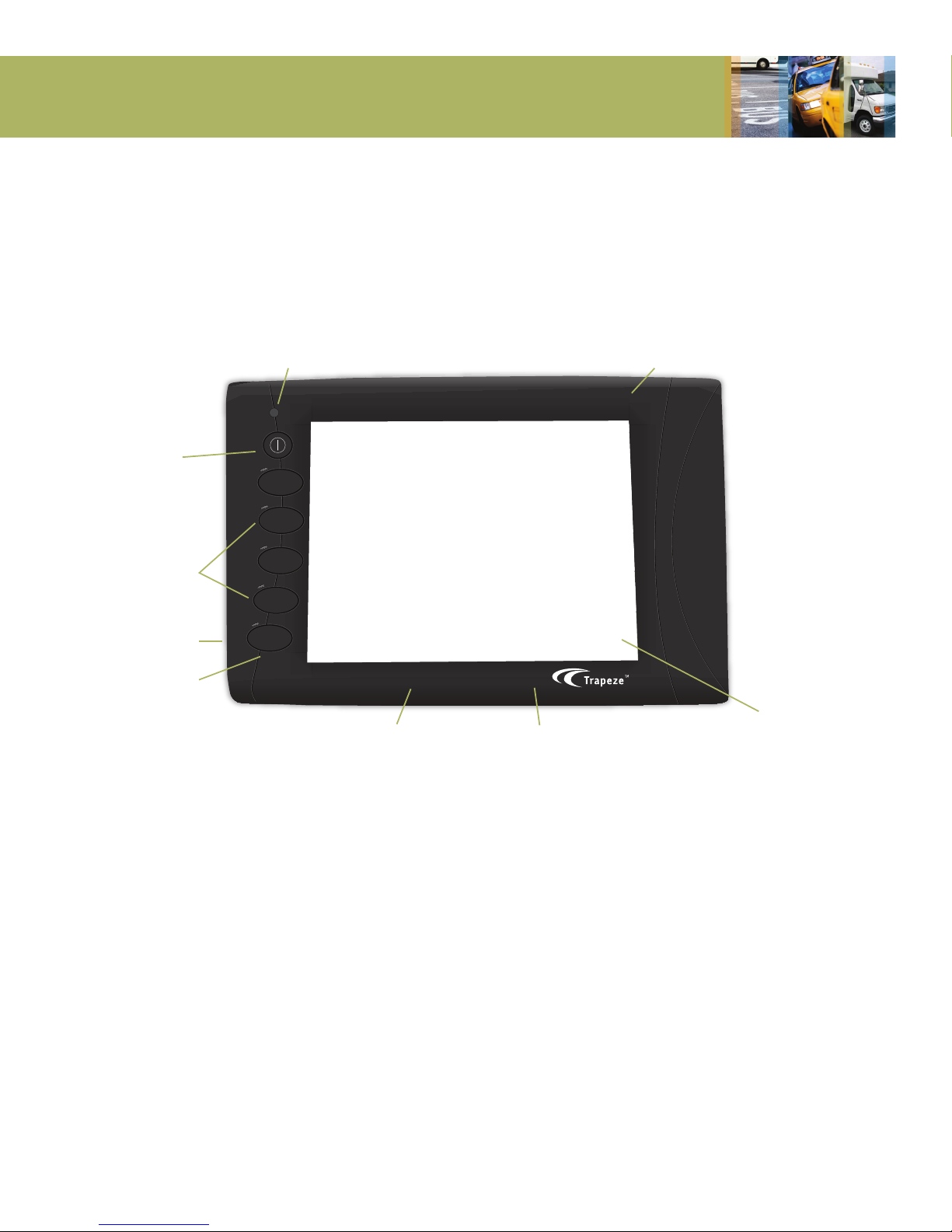
RANGER OVERVIEW
F1
F2
F3
F4
F5
Ambient Light Sensor Windows CE
6.5” VGA TFT
Backlit Color
Display &
Touchscreen
Internal Wi-Fi, Bluetooth Internal Cellular Modem
Microphone
Stereo Speakers
Function Keys
Power Key
6TRADE SECRET. Trapeze Proprietary and Confidential. © 2013 Trapeze Software ULC, its subsidiaries and affiliates. All rights reserved.
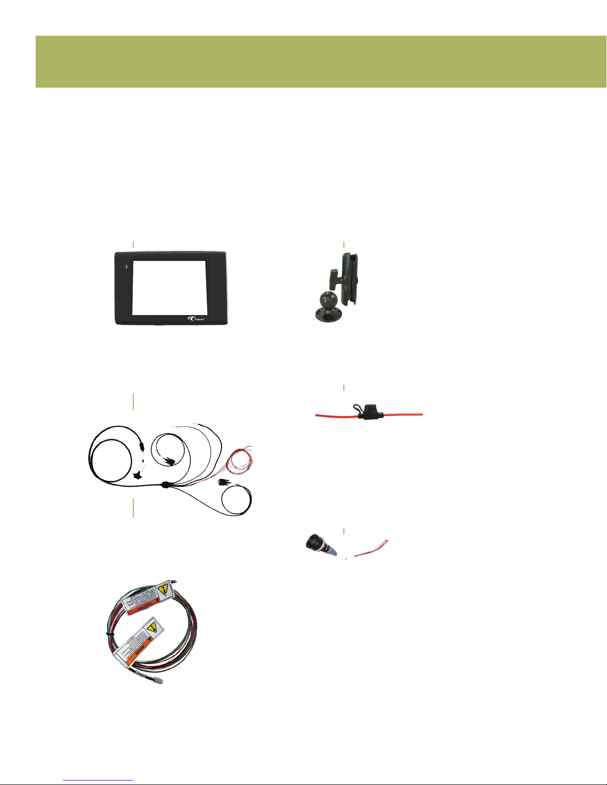
Ranger
Ranger Interface Cable
Ranger Power Pigtail
Ranger Mount
In-line Cable Fuse(s)
In-line cable fuse holder. Two holders and fuses
are supplied. The 3 Amp fuse is for power and
the 2 Amp fuse for the igntion input.
SUPPLIED (OPTIONAL)
Emergency switch
NOT SUPPLIED
• Zip Ties
• Glued Heat Shrink
• Tools as Required
• Grommets
• Loom
• Fasteners
Please verify that you have everything that you need to complete the Ranger installation.
NOTE: Not all parts are provided by Trapeze.
SUPPLIED
PARTS LIST
F1
F2
F3
F4
F5
4-CAS-PIGTMMLX20-00

7
TRADE SECRET. Trapeze Proprietary and Confidential. © 2013 Trapeze Software ULC, its subsidiaries and affiliates. All rights reserved.
MOUNTING LOCATIONS
Placement
1. Ensure that the driver’s view of the road will not be impacted.
2. Ensure that the equipment will not be in the path of any active airbags.
3. Ensure that the driver will still have access to all controls on the dash.
4. Ensure that the driver has a clear view of the terminal from the seated
driving position.
5. Ensure that the terminal is within easy reach of the driver from the seated
driving position.
6. Ensure that the mounting location is a solid surface. Locations that allow even
small amounts of initial movement will loosen over time.
7. Before drilling any holes or using screws, check for vehicle wiring under the
carpet or behind the instrument panel which could be pinched, cut or otherwise
damaged.
8.Ifmountingthroughtheoor,putbodysealerovertheunderbodyprojections.
Stampedacornnuts,lledwithsealer,areavailableatmostbodyshopsfor
this purpose. This will keep moisture out of the carpet and insulation and will
forestall rust in this area.
9. If mounting under the instrument panel, be sure that there is no interference
with proper operation of the foot controls.
10. Inquire if the vehicle will be cleaned with a high pressure water wand. If so,
ensure that all equipment is installed somewhere that will be protected from
this type of cleaning.

8TRADE SECRET. Trapeze Proprietary and Confidential. © 2013 Trapeze Software ULC, its subsidiaries and affiliates. All rights reserved.
Ranger Installed in an
Orion II Bus
Ranger Installed in a
Ford E-Series Cutaway
Ranger Installed in a
Chevrolet 3500 Series Cutaway
EXAMPLES OF SUITABLE MOUNTING LOCATIONS
RANGER MOUNTING EXAMPLES
9
TRADE SECRET. Trapeze Proprietary and Confidential. © 2013 Trapeze Software ULC, its subsidiaries and affiliates. All rights reserved.
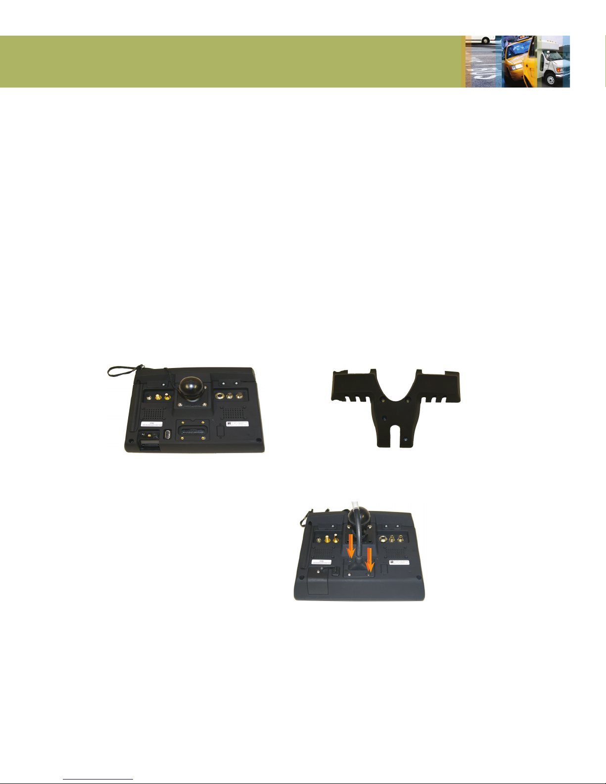
INSTALLING THE RANGER COVER PLATE
Ranger Back View
STEP 1
Connect the Ranger power cable
to the power input as shown.
Use 2mm screws and fasten cover.
This requires a 2mm Hex bit.
Torque main cable cover screws to
80 - 90 oz-inches (55 - 65 N-cm).
Ranger Back Cover Plate
SUPPLIES REQUIRED TO INSTALL COVER
In order to install the Ranger Cover, the following
items will be used. Most items are included in your
shipment of Ranger equipment:
- Ranger Cover Plate
- 6mm hex head screw (Quantity 2)
- 2mm hex head screw (Quantity 2)
- Hex bit, for 2mm hex head screws
- 5/16” wrench (torque wrench preferred) **
**Not included
10 TRADE SECRET. Trapeze Proprietary and Confidential. © 2013 Trapeze Software ULC, its subsidiaries and affiliates. All rights reserved.
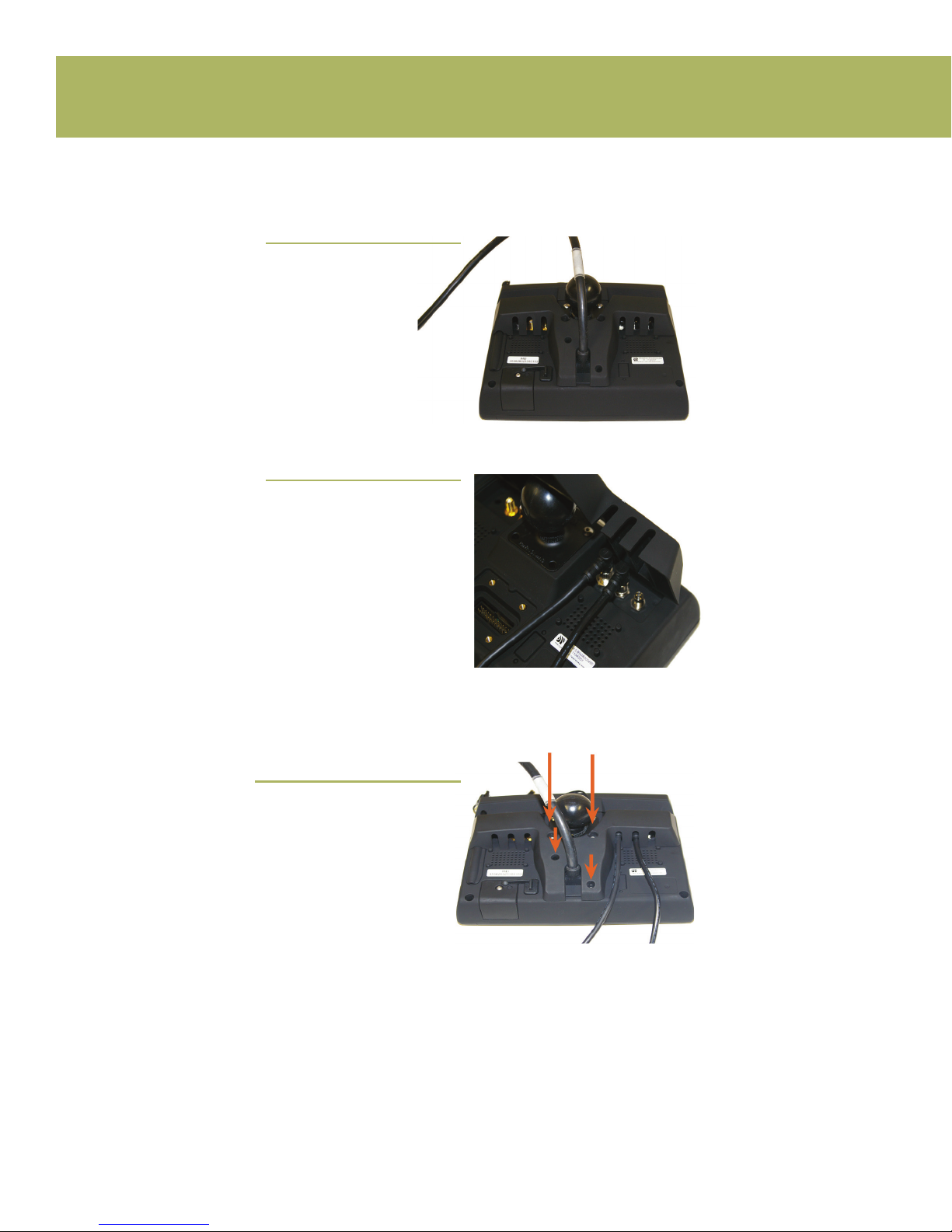
INSTALLING THE RANGER COVER PLATE
STEP 2A
Align the back cover
plate with the Ranger
as shown.
STEP 2B
If there are external cables
connected to the Ranger,
ensure to thread the cables
through the holes in the cover.
The cables must be threaded
in such a way that they are
not pinched by the cover when
fastened to the Ranger.
If an optional WiFi antenna is
provided, torque the R-SMA
connector to 140 oz-inches
(100 N-cm).
STEP 3
Secure the cover to the Ranger
with the screws provided. This
will require 6mm and 2mm hex
head screws (2 of each).
Torque mounting ball and RF
cable cover screws to 80 - 90
oz-inches (55 - 65 N-cm).

11
TRADE SECRET. Trapeze Proprietary and Confidential. © 2013 Trapeze Software ULC, its subsidiaries and affiliates. All rights reserved.
TORQUE SETTINGS
Thereareanumberofitemsthatmayneedtobeinstalledtoaspecictorquelevel.
This includes the Main Cable Cover, Mounting Ball, RF Cable Cover and antennas.
The following Table lists the recommended torque settings for installing these items.
Over and under torquing can lead to product damage and/or failure.
We recommend using a calibrated torque screwdriver for tightening all screws.
A Huber Suhner SMA torque wrench (74Z-0-0-21) is recommended for tightening
the Antenna cable.
INSTALLING THE RANGER COVER PLATE
Description Trapeze Part Number
Recommended Torque
Oz.In N.cm
Main Cable Cover 3-ENC-RNGRP226-XX 80-90 55-65
Mounting Ball 6-MNT-RAMCMN3X-XX 80-90 55-65
RF Cable Cover 3-ENCRNGRP301-XX 80-90 55-65
R-SMA Antenna Cable 6-ANT-XXXXXXXX-XX 140 100

12 TRADE SECRET. Trapeze Proprietary and Confidential. © 2013 Trapeze Software ULC, its subsidiaries and affiliates. All rights reserved.
WIRING Ranger Back View

13
TRADE SECRET. Trapeze Proprietary and Confidential. © 2013 Trapeze Software ULC, its subsidiaries and affiliates. All rights reserved.
WIRING Ranger Back View
DB9
DB9
1x3
Molex
2x2
Molex
Comm 1
RS 232
Serial Port
Minimum Required Connections Cable P/N:
4-CAS-PIGTMMLX20-00
Ranger Power Pigtail Cable P/N:
4-CAS-RNG4MUL310-00
(Ships attached to Ranger)
Comm 2
RS 232
Serial Port
J-1708
Contact Trapeze
Vehicle Specialist for
application details
Red 3A
Black
Green 2A
White
Blue GPI01
Violet GPI02
Orange GPI03
Yellow GPI04
Red
Green
Vin, 12/24/ v
Ground
Ignition Sense
Odometer
(typically not used)
Optional Emergency
Switch
Normally closed SPDT

14 TRADE SECRET. Trapeze Proprietary and Confidential. © 2013 Trapeze Software ULC, its subsidiaries and affiliates. All rights reserved.
1. SPLICING
T-Taps are not a suitable form of splicing into existing cabling. All splices must be
soldered and glued. Heat shrink must be used for protection.
2. POWER
Power connections should be made directly to the battery and fused as close to the
battery as possible. Avoid using a cigarette lighter or “Power Point” receptacles as
power sources. Trapeze does not recommend wiring power directly to a vehicle kill
switch because the Ranger will not power down correctly. Appropriate fuses are pro-
vided with the installation equipment.
3. GROUND
The ground point should be that point where the (-) terminal from the battery is
connected to the body. This connection to the battery is typically a 6 or 8 AWG
black wire connected to the wheelhouse or radiator support.
Do not fuse the ground lead. If the ground-side fuse were to open, the entire sup-
ply current would be conducted by an alternate current return path, which may
cause the feed line to overheat possibly resulting in damage.
4. SWITCHED IGNITION POWER
It is important to utilize an unused ignition point. Connecting to an ignition point
that is currently being used to switch other devices can cause improper operation of
those devices.
There are two methods for interfacing to the vehicle ignition. If neither of these
options are possible, then contact your Trapeze representative and alternate ignition
options can be discussed and approved.
Itishighlypreferabletondanignitionsourcethatgoeshighonlywhentheengine is
actually on. If this source cannot be found, an ignition source that goes high only when
the ignition is in the ON position is the next recommended source.
A) AUXILIARY ELECTRICAL PANEL (PREFERRED)
Many bus manufacturers will include an auxiliary electrical panel for interfacing periph-
eral devices. Below is an example of a common location in buses with a Ford chassis.
One of these terminals will typically be a switched ignition point. A ring terminal should
be used when connecting to this type of ignition interface point. Ask the local mainte-
nance personnel if you need assistance to find this panel.
CONNECTION POINTS
Table of contents
Popular Automobile Accessories manuals by other brands

Go groove
Go groove SMARTmini AUX operating manual

Air Design
Air Design SILVERADO 2014 + installation manual

Premier Manufacturing Co.
Premier Manufacturing Co. 240KSA Installation, Inspection, Operation & Maintenance Guide

MRHANDSFREE
MRHANDSFREE Blue Multi user manual

FormFit
FormFit Tough Guard TG 7W07 installation instructions

TigerTough
TigerTough 182103 installation guide


FormFit
FormFit HD 3A04 installation instructions

Let's Go Aero
Let's Go Aero TireBiter V-Rack product manual

TigerTough
TigerTough 32608 quick start guide

B-Link
B-Link SEMACONNECT 7 Series installation manual

Caraudio-Systems
Caraudio-Systems blueLOGiC BT-AU02 manual

Caraudio-Systems
Caraudio-Systems c.LOGiC C2-E65-TV manual