Travis Industries Tempest User manual

Tempest™ Lantern Wall Mount
(sku 94800831)
Page 1 of 11 17602174 - 2/17/21 © Travis Industries, Inc.
Overview
Tempest Lantern 24v (SKU 94900747 NG, 94900757 LP)
Tempest Lantern – Manual Ignition (SKU 94900746 NG, 94900756 LP) *
* This lantern will work with the wall mount. If installing a Manual Ignition lantern disregard instructions regarding the
electrical line.
Packing List
Control Cover
Post
Wall Plate Cover
Wall Plate with Post Bracket
Rough-in Template
Hardware Pack Components
Head Mounting Brackets
(4) 2-1/2” Stainless Steel Lag Bolts and Washers
½” FPT to ½” MPT Elbow
Shutoff Valve - ½” FPT to 3/8” Flare
3/8” x 16” Stainless Flex Tubing
3/8” to 3/8” Tubing Connector
a
c
d
f
e
g
b
a
b
c
d
e
f
g

Tempest™ Lantern Wall Mount
(sku 94800831)
Page 2 of 11 17602174 - 2/17/21 © Travis Industries, Inc.
Lantern Location – Clearance to Combustibles
The wall mount must be properly positioned to provide proper clearance to combustibles when the lantern is
attached. See the illustration below for details.
NOTE: If the siding is thicker than 1/2” (13mm) add material behind the lantern mount so the base is not
submerged more than 1/2” (13mm) into the siding.

Tempest™ Lantern Wall Mount
(sku 94800831)
Page 3 of 11 17602174 - 2/17/21 © Travis Industries, Inc.
Gas Line Location and Wall Plate Placement
The gas line must be located correctly to allow proper placement of the shutoff valve under the wall plate cover.
See the illustration below for details.
Tempest™ Lantern Wall Mount
(sku 94800831)
Page 4 of 11 17602174 - 2/17/21 © Travis Industries, Inc.
Installation
NOTE: The illustrations below are for example only. Make sure to follow all gas line and building code
requirements for your location.
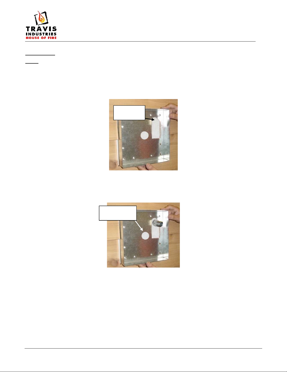
1. Make sure adequate framing is provided behind the wall to support the weight of the lantern. Install the
wall plate template in the desired location using the (4) included lag bolts. This template will help locate
where the gas line and electrical will penetrate the wall (see Figure 1).
Figure 1
2. Run the gas line to the correct location (see the illustration figure 3 details). Make sure the gas nipple
protrudes between ¾” and 1-1/2”
Figure 2
Stub in gas
line here
Install 24VDC
electrical here

Tempest™ Lantern Wall Mount
(sku 94800831)
Page 5 of 11 17602174 - 2/17/21 © Travis Industries, Inc.
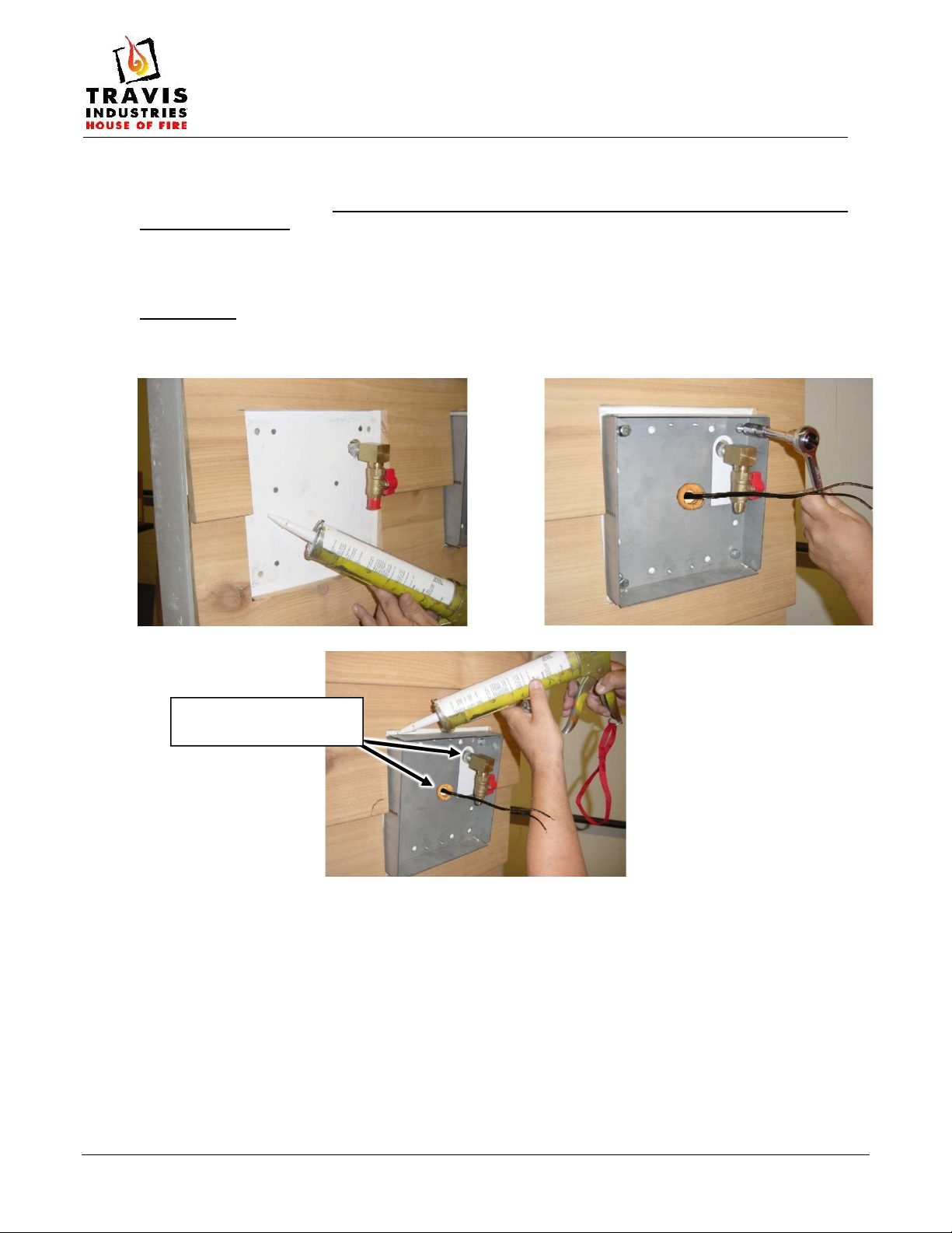
3. Attach the included elbow and shutoff valve to the nipple (use thread sealant, etc.). Make sure the elbow
is facing directly down and shutoff valve is facing outwards as shown in Figure 3. Run the electrical line
(if applicable) through the center hole of the wall plate and leave at least 14” of wire forward of the wall
plate.
NOTE: You may wish to pressure-test the gas line at this time.
NOTE: If you are doing this installation in two stages, you can now mask off the front of the template box
and finish material can be applied to the wall surface around the mount. You will remove the template
and replace with the wall plate when the site is ready for final installation.
Figure 3
4. Place the wall plate on a suitable work surface and remove the (4) nuts (and washers) that hold the post
bracket in place (see Figure 4). Remove the post bracket (see Figure 5).
Figure 4
Figure 5
Tempest™ Lantern Wall Mount
(sku 94800831)
Page 6 of 11 17602174 - 2/17/21 © Travis Industries, Inc.
5. Remove and discard the templet used in step 3 (set the (4) lag bolts aside for reinstallation). Place a ¼”
bead of silicone around the perimeter of the wall plate location (see Figure 6). This silicone will help
weatherize the wall mount. Seal the gas line and electrical penetrations and any exposed exterior
sheeting at this time. Secure the wall plate to the wall using the four lag bolts used to secure the
template in step 3 (see Figure 7) or other suitable means. Once the wall plate is in place, you may wish
to seal the area around the perimeter of the wall plate if it is exposed to weather (see Figure 8). Make
sure the sealant does not interfere with the cover plate – wipe off any excess sealant before proceeding.
WARRNING: Seal the penentrations for the electrical and gas lines. Negative pressure in the
building can cause heat failure of components.
Figure 6
Figure 7
Figure 8
Seal electrical and gas
line penetrations

Tempest™ Lantern Wall Mount
(sku 94800831)
Page 7 of 11 17602174 - 2/17/21 © Travis Industries, Inc.
6. With the rain cap off, turn the lantern upside down and place it on a soft surface to protect the finish.
7. Remove the (2) thumb screws that secure the bottom cover to the lantern (set aside for reinstallation).
Carefully remove the bottom cover from the lantern, make sure not to damage any gas or electrical
components.
8. Remove the hinged control cover from the front of the stock cover and install it on the cover included with
the wall mount kit.
Tempest™ Lantern Wall Mount
(sku 94800831)
Page 8 of 11 17602174 - 2/17/21 © Travis Industries, Inc.
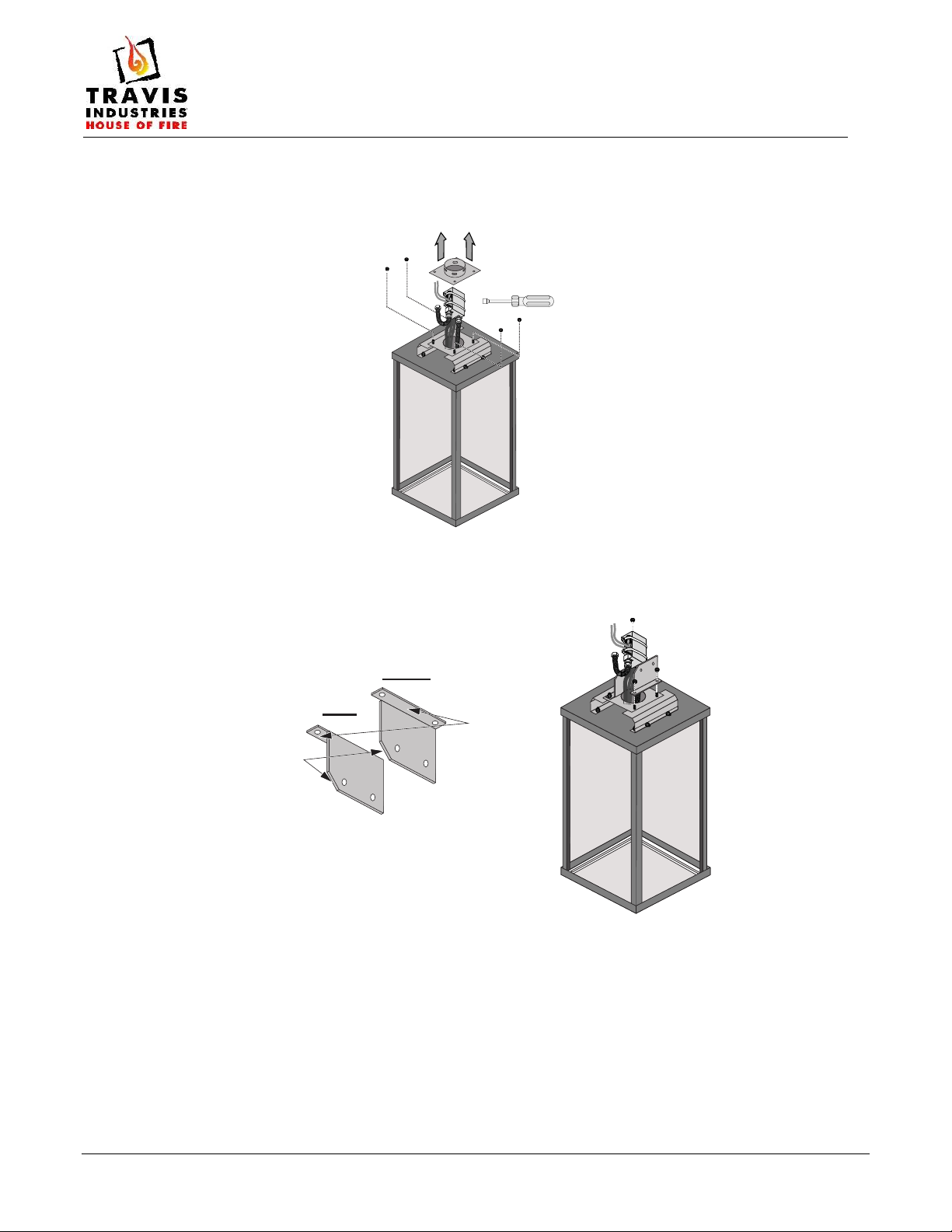
9. Use a 11/32” nutdriver to remove the (4) nuts that secure the mounting collar to the lantern. Carefully
remove mounting collar from the lantern base, make sure not to damage any gas or electrical
components. Discard the collar. Keep the nuts for reinstallation.
10. Install the wall mount brackets onto the lantern base. Make sure the brackets are oriented properly. The
lopped corners should face the front of the lantern and the tabs face to the outside (see illustration
below). Use the nuts removed in the previous step to secure the brackets to the base.
11/32” Nutdriver
Left
Right
Tab faces
out
Lopped
corners
to front

Tempest™ Lantern Wall Mount
(sku 94800831)
Page 9 of 11 17602174 - 2/17/21 © Travis Industries, Inc.
11. Place the post on a suitable work surface and remove the (2) through-bolts (with washers and nuts) and
the (2) bolts (with washers) from the threaded holes on the top of the post. Use the (2) through-bolts
(with washers and nuts) to secure the post bracket to the post (see Figure 11). Attach the (2) top bolts
through the leveling bracket (pre-installed on the post bracket) into the post – DO NOT OVERTIGHTEN
THESE BOLTS – THEY THREAD INTO THE ALUMINUM POST (see Figure 12)
Figure 11
12. Guide the electrical wire through the post. Position the post assembly over the wall plate and line up the
holes in the post bracket with the studs on the wall plate (see below). Attach the post with the four nuts
(and washers) removed in step 4.
NOTE: You may wish to level and square the wall mount if post does not appear correct. Washers may
be placed between the post bracket and wall plate to shim the post to the correct position.

Tempest™ Lantern Wall Mount
(sku 94800831)
Page 10 of 11 17602174 - 2/17/21 © Travis Industries, Inc.
13. Slide the wall plate cover (Figure 12 – make sure it is positioned correctly – the circular indents are on
the sides), and control cover over the post (Figure 13). Leave the cover loose so gas connections can be
made
NOTE: The images below show the Tempest Torch version of the wall plate cover. The Tempest Lantern version has
a tapered appearance but attaches in exactly the same way.
Figure 12
Figure 13
14. Attach the flex tube and fitting to the gas inlet on the lantern (use adapter included in the hardware pack.
See figure 14). Route the flex tube and the gas control assembly so it angles back and slightly
downward. Insert the gas line and control assembly through the post,. Push the gas line all the way to
through to the mounting plate (see Figure 14,15 & 16). Grasp the end of the flex tube and pull it through
as you position the head mounting brackets over the outside end of the post and line up the holes in the
head mouting brackets with the holes in the mounting post (see Figure 17 &18). Attach the lantern to the
post using the through-bolts removed in step 8 (see Figure 19).
Figure 14
Figure 15
Figure 16
Figure 17
Figure 18
Figure 19
Other manuals for Tempest
2
This manual suits for next models
1
Table of contents
Other Travis Industries Lantern manuals


