Travis Industries Tempest Torch 24V User manual

Tempest Torch 24V
Owner’s Manual
Natural Gas (sku 94900745) -Propane (sku 94900755)
Tested
and
listed by
Portland OR
ANSI Z21.97-2014/CSA 2.41-2014, CGA 2.17-M91 (R2014)
Outdoor Decorative Gas Appliances - Report # 0028GM083S
WARNING: For Outdoor Use Only
WARNING: If the information in this manual is not followed exactly, a fire or explosion may result
causing property damage, personal injury or loss of life.
- Do not store or use gasoline or other flammable vapors and liquids in the vicinity of this or any
other appliance.
- An LP cylinder not connected for use shall not be stored in the vicinity of this or any other
appliance.
- Installation and service must be performed by a qualified installer, service agency or the gas supplier
DANGER
If you smell gas:
1. Shut off gas to the appliance.
2. Extinguish any open flame.
3. If odor continues, keep away from the appliance and Immediately call your gas supplier
or fire department.
WARNING: Improper installation, adjustment, alteration, service or maintenance can cause
injury or property damage. Read this manual thoroughly before installing or
servicing this equipment. For assistance or additional information consult a
qualified installer, service agency, or the gas supplier.
Installer: After installation give this manual to the homeowner and explain
operation of this appliance.
$10.00 Copyright 2018, T.I. Part # 100-01471

2Introduction
© Travis Industries, Inc. 3/20/18 - 1471 Tempest 24v
Overview
This manual details the installation, operation, and routine maintenance for the Tempest
torch.
Listing Details
This torch was tested to ANSI Z21.97-2014/CSA 2.41-2014, CGA 2.17-M91 (R2014)
“Outdoor Decorative Gas Appliances”.
Important Registration and Service Information
No other Tempest torch has the same serial number as yours. The serial number is on the
safety label attached by a chain near the control panel. This serial number will be needed in
case you require service of any type. To receive full warranty coverage, you will need to show
evidence of the date of purchase. Mail your warranty card or visit traviswarranty.com to register
your Tempest torch. If any service issues may arise, contact your dealer for details.

Table of Contents 3
© Travis Industries, Inc. 3/20/18 - 1471 Tempest 24v
Introduction
Overview............................................................. 2
Listing Details...................................................... 2
Important Registration and Service Information..2
Safety Precautions
Safety Precautions.............................................. 4
Features & Specifications
Features..............................................................5
Installation Options ............................................. 5
Specifications......................................................5
Dimensions......................................................... 5
Installation
Installation Warnings........................................... 6
Packing List.........................................................6
Additional Items Required...................................6
Recommended Order of Installation ................... 7
Placement Requirements....................................8
Gas Line Requirements ...................................... 9
Gas Line Connection .......................................... 9
Electrical Connection Requirements...................10
Wiring Diagram...................................................10
Wiring Multiple Torches to One Switch ...............11
Post Mount and Control Cover Installation..........15
Torch Assembly..................................................16
Optional Rain Cap...............................................17
Operation
Before You Begin................................................18
Operating Instructions.........................................18
Maintenance
Maintaining Your Torch.......................................19
Winterizing the Torch. .........................................19
Replacement Parts..............................................20
Troubleshooting Table ........................................21
Warranty
Warranty..............................................................22
Index
Index ...................................................................24

4Safety Precautions
© Travis Industries, Inc. 3/20/18 - 1471 Tempest 24v
! This appliance must be installed in accordance with all local codes, if any; if not, follow
ANSI Z223.1.
! This appliance must only be used outdoors in a well-ventilated area. It may not be used
in a building, garage, or other enclosed space.
• This appliance is not for use with solid fuel.
• The torch must be kept clean and free of leaves and debris to insure safe operation.
• Any hose or gas-supply line that is damaged or shows evidence of excessive abrasion or wear must be
replaced prior to use of the torch.
• If using a gas supply line to the torch, make sure it is properly located away from any walkway or in an
area where it may be subject to accidental damage
• Educate all children and adults of the dangers of the torch. Young children should be supervised when
they are in the same area as the torch. Do not let children play with the torch.
• Do not place clothing or other flammable items on or near the torch.
• Any screen or guard removed for servicing must be replaced prior to operating the torch.
• This unit must be installed and repaired by a qualified installer to prevent the possibility of an explosion.
Your dealer will know the requirements in your area and can inform you of those people considered
qualified. The torch should be inspected before use and at least annually by a qualified service person.
More frequent cleaning may be required due to excessive debris from leaves, dirt, insects, etc.
• Do not use this appliance if any part has been under water. Immediately call a qualified service
technician to inspect the appliance and to replace any part of the control system and any gas control that
has been under water.
• The instructions in this manual must be strictly adhered to. Do not use makeshift methods or compromise
in the installation. Improper installation will void the warranty and safety listing.
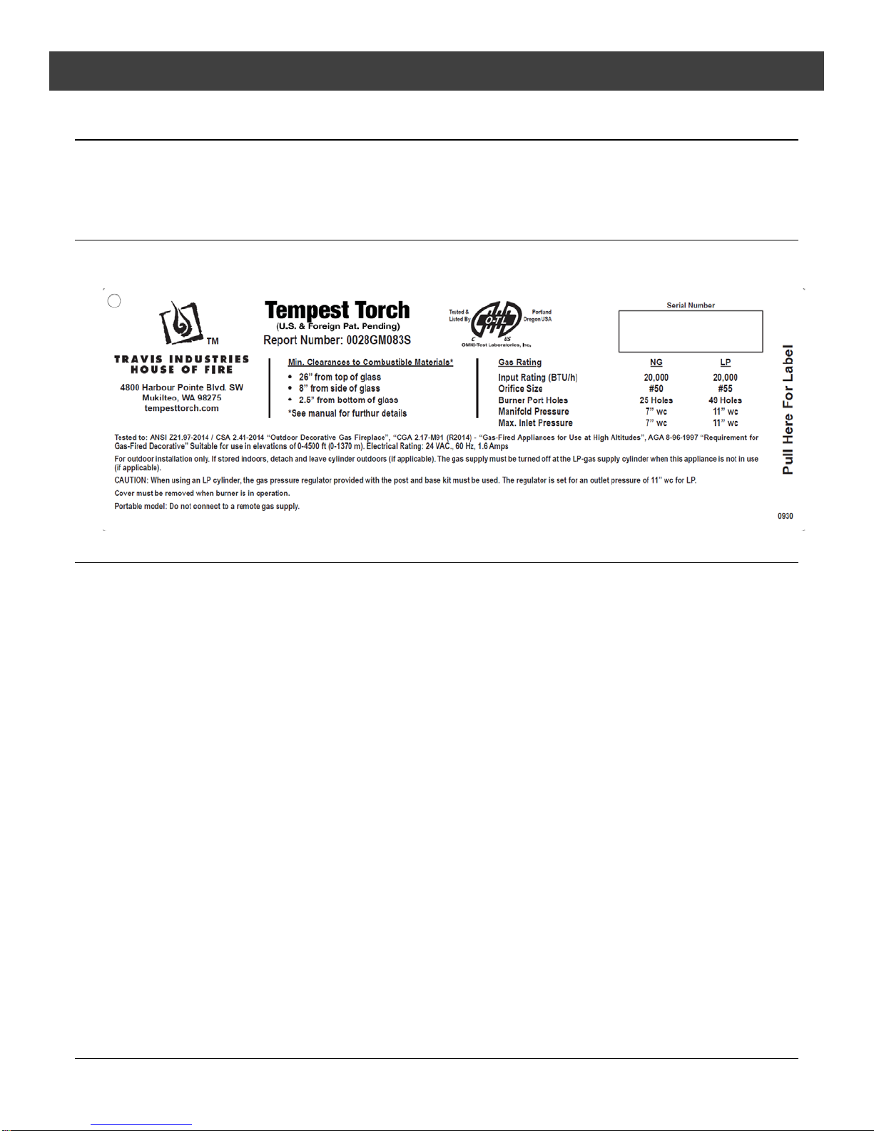
• This appliance is approved for either natural gas (NG) or propane (LP). Burning the incorrect fuel will
void the warranty and safety listing and may cause an extreme safety hazard. Direct questions about the
type of fuel used to your dealer. A label is placed on the control panel to show which fuel the torch is
designed for (in addition, NG units have 25 burner holes, LP units have 49 burner holes).
• Contact your local building officials to obtain a permit and information on any installation restrictions or
inspection requirements in your area.
• If the flame becomes sooty, dark orange in color, or extremely tall, do not operate the torch. Call your
dealer and arrange for proper servicing.
• Do not operate the torch if it is not operating properly in any fashion or if you are uncertain. Call your
dealer for a full explanation of your torch and what to expect.
• Do not store or use gasoline or other flammable liquids in the vicinity of this torch.
• Never remove, replace, modify or substitute any part of the torch unless instructions are given in this
manual for routine maintenance and cleaning. A trained technician must do all other work. Do not modify
or replace orifices.
• Allow the torch to cool before carrying out any maintenance or cleaning.
• Operate the torch according to the instructions included in this manual.
• If the burner does not start correctly turn the gas off at the gas control valve and call your dealer for
service.
• Do not use this appliance to cook food.
• Instruct everyone in the house how to shut gas off to the torch and at the gas main shutoff valve. The gas
main shutoff valve is usually next to the gas meter or propane tank and requires a wrench to shut off.
• Do not operate the torch during a lightning storm or a possible lightning storm.
• Do not operate the torch during high wind conditions.
• Do not install in or on recreational vehicles and/or boats.
• Do not throw this manual away. This manual has important operating and maintenance instructions that
you will need at a later time. Always follow the instructions in this manual.
• Travis Industries, Inc. grants no warranty, implied or stated, for the installation or maintenance of
your torch, and assumes no responsibility of any consequential damage(s).

Features and Specifications 5
© Travis Industries, Inc. 3/20/18 - 1471 Tempest 24v
Features:
- Electronic Ignition (switch turns torch on or off)
- Maximum 20,000 BTU Input
- Removable Rain Cap
- Tempered Glass (easy to remove and clean)
- Stainless Steel Construction
- Automatic Gas Shutoff Valve for Safety
Installation Options:
- For Outdoor Installation Only
- For Fixed Line Installations Only
- Wall Mount
- Post Mount
- Pillar Mount
Gas Specifications:
NG
LP
Input Rating (Btuh)
20,000
20,000
Orifice Size (DMS)
#50
#55
Burner Ports
25 Holes
49 Holes
Manifold Pressure
7" wc
11" wc
Max. Inlet Pressure
7" wc
11" wc
Electrical Specifications:
24 Volts AC, 1.6 amps (on startup), 40 watts (on startup)
Dimensions:
NOTE: All Clearances are measured from the glass (and glass frame).

6Operation
© Travis Industries, Inc. 3/26/18 - 1471 Tempest 24v
Installation Warnings:
! This appliance is designed for outdoor use only, in well-ventilated areas.
! Failure to follow all of the requirements may result in property damage, bodily
injury, or even death.
! This torch must be installed by a qualified installer.
! This appliance is designed to operate on natural gas, or propane (LP).
! This appliance requires a switched, 110v AC, GFCI (ground-fault interrupt circuit)
protected power supply. This circuit provides power to the 24v AC transformer
(not supplied).
! Notify your insurance company before hooking up this appliance. All relevant
information on the Tempest Torch is located on page 2, Important Information.
You can fax them page 2.
! The requirements listed below are divided into sections. All requirements must be
met simultaneously. The order of installation is not rigid – the qualified installer
should follow the procedure best suited for the installation.
Packing List
Main Assembly
Burner Top
(4) Support Bars (w screws)
Top Plate
Rain Cap
5/32” Hex Wrench
Control Cover (pre-installed)
(4) ¼-20 x ½” Hex Head Screws
12” Long ½” Flex Tube with Shutoff Valve (accepts ½” MPT)
(4) #6 x 1” Screws (used to secure control module to wall or other structure)
Glass (4 Pieces)
3/8” – ½” Flare Reducing Coupler (100-05144)
Additional Items Required
This Torch Requires One of the Following Base Assemblies:
Wall Mount Kit
Post Mounting Kit
Pillar Mounting Kit
This Torch Requires a 24Volt AC transformer.
Travis Industries 24V AC Transformer (94800829)

Operation 7
© Travis Industries, Inc. 3/20/18 - 1471 Tempest 24v
Recommended Order of Installation
1. Determine the location of torch. Make sure all clearances are met, (see page 8).
2. With the torch head location identified, prepare and mount the torch head support (pillar, post, or
wall mount). This order of installation may need to be modified due to individual installation
conditions. NOTE: sections 4, 5, 6 and 7 of this page detail gas and electrical connections to the
torch head.
3. GAS SUPPLY: The torch requires 20,000 BTU input (natural gas or LP). A shut off valve and 12
inches of flex line are provided to assist connection from the supply line to the torch head. The
shutoff valve accepts ½” MPT (male pipe thread). Before turning gas on to the torch, leak-test all
gas line connections.
4. ELECTRICAL SUPPLY: The power supply must be routed through a switch to turn the torch on
and off (see page 10). Multiple torches may be placed on a single circuit. Each torch uses
24VAC at approximately 1.6 amps - make sure the circuit and wiring is appropriately sized (see
diagram on pg 11.). If multiple torches are powered through a single switch, the control modules
for each of the individual torches may be daisy-chained together (make sure polarity is correct,
see pg. 13). Make sure to leave slack in the electrical line so the head can be removed for
service.
5. For outside post and pillar installations route a ½”stainless steel flexible gas line from the shut off
valve to the torch head (you will have to provide this gas line).
For wall mount applications; if using flex line to pass through the wall of a building the flex line
must be enclosed in conduit for protection, or local code may require you to hard pipe the
connection from the control module to the torch head.
6. Attach the torch head to the mount. Attach the gas line. Attach the 24vac electrical supply.
Leave the control covers loose to allow for leak testing access. Install the torch assembly (see
page 16).
7. Bleed the gas line and start the torch by switching on the electrical power to the control module.
Leak test the gas lines. Verify the torch works correctly and there are no gas leaks. Attach the
control covers.
8. Give the manual to the home owner and explain the operation of the torch.

8Operation
© Travis Industries, Inc. 3/20/18 - 1471 Tempest 24v
Placement Requirements
! For Outdoor Use Only. Install in well-ventilated areas.
Do Not Locate the Torch:
•In high traffic areas.
•Under or near trees, plants and buildings where debris may constantly fall into the torch.
Excessive debris will require high maintenance and/or cause malfunctioning of the torch.
•In places where people, children, and pets may contact the torch. Guards or fences
around the torch in these locations are recommended.
•In places where the controls beneath the torch may be submerged under water.
Submerging of any part of its controls may require complete replacement of the controls.
Clearances:
•The distance from ground level to the top of the torch shall be a minimum of 7 ft. (2.1M)
where installed within 2 feet (0.6M) of public walkways (e.g.: sidewalk, shared walkway
between two homes, or pathway in commercial applications). Lesser clearances shall be
permitted to be used only where acceptable to the authority having jurisdiction.
•Keep combustibles away from the shaded heat zone of the torch (see illustration below).

Operation 9
© Travis Industries, Inc. 3/20/18 - 1471 Tempest 24v
Gas Line Requirements
MASSACHUSETTS INSTALLATIONS - WARNING:
THIS PRODUCT MUST BE INSTALLED BY A LICENSED PLUMBER OR GAS FITTER WHEN INSTALLED WITHIN THE
COMMONWEALTH OF MASSACHUSETTS.
OTHER MASSACHUSETTS CODE REQUIREMENTS:
•Flexible connector must not be longer than 36 inches.
•Shutoff valve must be a “T” handle gas cock.
•Only direct vent sealed combustion products are approved for bedrooms or bathrooms.
•Fireplace dampers must be removed or welded in the open position prior to the installation of a fireplace insert or gas log.
•A carbon monoxide (CO) detector is required in the same room as the appliance.
! The gas line must be installed in accordance with all local codes or, in the absence of local codes, with the
National Fuel Gas Code, ANSI Z223.1/NFPA 54, International Fuel Gas Code, Natural Gas and Propane
Installation Code, CSA B149.1, or Propane Storage and Handling Code, B149.2, as applicable. Consult your
local gas supplier or propane gas dealer for code regulations and recommended procedures.
! The torch and gas control module must be disconnected from the gas supply piping during any pressure testing
of that system at test pressures in excess of 1/2 psig. For pressures less than 1/2 psig, isolate the gas supply
piping by closing the manual shut-off valve.
! Leak test all gas line joints and the gas control valve prior to and after starting the torch.
LP and NG Configuration
This torch is shipped either for natural gas or for propane. The torch is not convertible from one fuel to another.
Check the sticker on the control panel to make sure the correct fuel is used. The torch has unique orifices and
burners for each fuel. See the table below for details.
NG
LP
Input Rating (Btuh)
20,000
20,000
Orifice Size (DMS)
#50
#55
Burner Ports
25 Holes
49 Holes
Manifold Pressure
7" wc
11" wc
Max. Inlet Pressure
7" wc
11" wc
Gas Line Connection
A manual shutoff valve is required on the gas supply to the torch. It should be placed upstream of the control
module. A shut-off valve is included with the torch.

10 Operation
© Travis Industries, Inc. 3/20/18 - 1471 Tempest 24v
Electrical Connection Requirements
! The appliance, when installed, must be electrically grounded in accordance with local codes, or in the
absence of local codes with the National Electrical Code, ANSI/NFPA 70; or the Canadian Electrical
Code, CSA C22.1
! The electrical line must be installed by a qualified installer and must meet all local codes. Consult
your local building official for code regulations and recommended procedures.
! The 24VAC transformer may require a circuit protected by a GFCI (see local building codes).
!
NOTE: Tempest Torch offers a 24v transformer (sku# 94800829) that is able to power between 1 and 4 torch
heads. Contact your local Tempest Torch dealer for details.
Wiring Diagram
•We recommend outdoor-suitable connectors (silicone-filled wire connectors, dielectric grease,
etc.) on the power-in connections to the control module to prevent corrosion.
•Route the wires from the 24VAC transformer to the torch using listed wiring. The wiring is routed
through the post or wall mount. Make sure to provide slack in the electrical line for removal and
service.
•Each torch uses approximately 40 watts during startup (1.6 amps at 24VAC). Make sure the
circuit and wire are sized appropriately.
* NOTE: The thermopile must connect to the control module as shown above (orange/white
wire connects to the white thermopile wire and orange wire connects to red
thermopile wire). Do not reverse the wires. If the wires are reversed, the torch will
not work correctly.
orange *
red/black
orange/white *
green
white
white/blue
red/green
black
black
red *
white *
green/yellow
white
white

Operation 11
© Travis Industries, Inc. 3/20/18 - 1471 Tempest 24v
Wiring Multiple Torches to One Switch
•Multiple 24VAC transformers may be wired to a single switch (see diagram below).
Wiring Multiple Torches to One Transformer
The torches can be “Daisy Chained” together or each torch can be a “Home Run” back
to the transformer.
Polarity must be maintained in all multiple torch installations. Failure
to maintain polarity will result in damage to the control module.
Example A
Example B

12
Operation
© Travis Industries, Inc. 3/26/18 - 1471 Tempest 24v
Wiring Sizing / Length
Each torch is connected to the 24VAC power line near the torch head. This allows the installer to
daisy chain one torch to another (see “Example A” on previous page). This may be useful when
a number of torches are closely spaced.
Maximum Wire Length Per number of torches and wire gauge
AWG 1 2 3 4
14 235' 110' 70' 50'
12 325' 155' 100' 70'
10 445' 220' 145' 110'
NumberofTorches
MaxWireLength
Maximum (4) torches per transformer
Up to (7) transformers per 120V, 15amp circuit
Up to (28) torches per 120V, 15amp circuit
Examples of Maximum Wire Length
Maximum length is determined by wire gauge, number of torches, and torch configuration (see
chart above).
-- The more torches on one wire, the shorter the maximum length
-- The larger the wire, the longer the maximum length
-- “Home Run” configurations allow for greater wire length than “Daisy Chained” configurations
– The maximum wire length is determined by voltage drop of the wire. Use of a larger 24v
transformer does not influence wire length
If using a multi-tap transformer (24v, 27v, etc.) maximum wire length may be greater. Consult an
electrician for details.
The example below uses a “Home Run” configuration. Because each wire serves only one torch,
the maximum wire length can be run.

Operation 13
© Travis Industries, Inc. 3/20/18 - 1471 Tempest 24v
Examples of Maximum Wire Length (continued)
The example below uses a “Daisy Chained” configuration. Because each wire serves 4 torches,
total wire length (35’ + 25’+ 25’+ 25’ = 110’) is limited to 110’ (see chart above). .

14 Operation
© Travis Industries, Inc. 3/20/18 - 1471 Tempest 24v
Polarity
WARNING: Make sure to keep polarity between torches the same.
Do not allow a white wire to connect to a white/blue wire (keep polarity the same).
IF YOU REVERSE POLARITY, PERMANENT DAMAGE WILL OCCUR.
•When wiring multiple torches together using a single 24VAC transformer, it is important that the
polarity between the torches are connected in parallel (all white wires connected together and
all white/blue stripe wires connected together). Polarity between the torches and the
transformer does not matter.

Operation 15
© Travis Industries, Inc. 3/20/18 - 1471 Tempest 24v
Post Mount and Control Cover Installation
A post mount is pre-attached to the torch for use with the optional post (3” round lamp post) or pillar mount.
If using the wall mount, use the control cover included with the wall mount kit.
(a)
If using a post mount, slide
the control cover over the
post.
HINT: Use low-tack tape to
protect the post from
scratches.
NOTE: When installing the
post, make sure the post is
positioned with the
mounting holes 45° offset
from the front. The post
mount has obround holes
that allow 20° of rotation
(10° in each direction).
(b)
Attach the gas and
electrical lines.
WARNING: Take care
when handling the torch
assembly to not damage
the gas or electrical line.
(c)
Attach the torch to the post
using the included ¼-20
screws.
(d)
Attach the control cover to
the torch with the two thumb
screws.
! The safety label slides
into place between the
control cover and the
torch body.

16 Operation
© Travis Industries, Inc. 3/20/18 - 1471 Tempest 24v
Torch Assembly
(a)
Place the burner top over the
main assembly. Make sure the
burner top is fully seated.
! Make sure the igniter element
lines up with the hole on the
burner top.
(b)
The support bars are shipped
with two screws pre-installed.
Remove the screws from the
support bars and attach the four
bars to the main assembly.
Make sure the bars are properly
aligned (square to the edge of
the main assembly).
(c)
Attach the top plate.
NOTE: If using the optional rain
cap, you may wish to install it
now before the glass is installed
(see page 13).
(d)
Slide one piece of glass into
place until it contacts the support
bar.
! Make sure the teflon tape is at
the top of the glass with the
wrap-around edge facing
inwards.
HINT: Make sure the glass is
clean before installing and
handle with soft gloves or other
non-marking material (e.g. paper
towel).
(e)
Use a 5/32” hex wrench to
tighten the glass support bolt.
!Tighten the bolt only enough to
hold the glass in place – over-
tightening may break the
glass.
Repeat steps “d” and “e” for the
other three pieces of glass.

Operation 17
© Travis Industries, Inc. 3/20/18 - 1471 Tempest 24v
Optional Rain Cap
The optional rain cap may be installed to suit the installation location. If the torch is located in an area
where rain or plant debris is prevalent, you may wish to permanently mount the rain cap to the torch with
the included nuts.
Place the rain cap on top of the torch so the four studs insert through the top plate. With one or two
pieces of glass removed, secure the rain cap using the included nuts (shipped pre-attached to the rain
cap).
WARNING: Do not use the torch cover (sku 94800867) with electronic ignition torch. The cover will combust if
in place while the torch is turned on, creating a severe safety hazard.

18 Operation
© Travis Industries, Inc. 3/20/18 - 1471 Tempest 24v
Before You Begin
! Read this entire manual before you use your new torch, especially the section "Safety Precautions" on
page 4. Failure to follow the instructions may result in property damage, bodily injury, or even death.
! Remove any cover from the torch prior to operation (the optional stainless-steel rain cap may be left in
place.
! Inspect the torch to make sure it is free of debris or objects that may have fallen into the torch prior to
operation.
! Inspect the torch, burner, and supply lines for any damage prior to operation. The burner must be
replaced prior to the appliance being put into operation if it is evident that the burner is damaged. Use
only Travis Industries replacement burners.
! It may be difficult to see the burner operating in direct sunlight.
! WARNING: Do not use the torch cover (sku 94800867) with electronic ignition torch. The cover will
combust if in place while the torch is turned on, creating a severe safety hazard.
Operating Instructions
WARNING: This gas torch is automated, it runs off of an electric ignition system and may not be lit with
a lighter or matches.
How your torch works
Ignition
When you switch the torch on, electrical power is supplied to the control module, starting the ignition sequence.
During ignition the igniter will glow red (the ignitor is visible behind the burner rings on the torch). Gas is then
turned on to the torch. The torch will ignite and the flame sensor will signal the control module that the torch is lit
and the igniter will then turn off.
NOTE: In rare cases, the torch will fail to light. In these cases the torch will wait 30 seconds, then re-start the 35-
second ignition sequence. The control module will try to re-start the torch a total of 3 times. If it fails to light after
three tries, the torch will then shut-off. To re-start, turn the switch off, wait 3 seconds, then turn the switch on.
Torch in Operation
The torch, once lit, will stay lit until power to the torch is turned off. If gas flow is interrupted, or if wind blows-out
the flame, the torch will start the ignition sequence. If you cycle power to a Hot torch (turn off and back on) it may
take up to 1 minute for the torch to start the ignition sequence.
Multiple Torches
Each torch operates independently. If you install multiple torches on one power switch and need to turn one of
the torches off, shut the gas off to the specific torch. Shutting one torch off will not affect the others.
Safety Circuit
Each torch has a built in safety circuit that only allows gas to flow during the ignition sequence and when the torch
is lit. This prevents gas build-up. The safety circuit relies upon a flame sensor to keep the gas valve open. If the
flame goes out the control module will shut the gas off then try to relight the torch. Your torch can not be operated
manually, if a problem persists consult the trouble shooting guide (pg 21) and call a qualified service technician if
needed.
Torch Operation Options
Your torch is operated from an electrical circuit similar to an exterior light. You can set up one or many torches on
a single power supply. Torches may be set up and operated from any system that a house or exterior light could
be operated from. Some examples are:
•Wall switch
•Timer
•Smart home control system
•Remote control

Maintenance 19
© Travis Industries, Inc. 3/20/18 - 1471 Tempest 24v
Maintaining Your Torch
! Failure to inspect and maintain may lead to malfunctioning of the appliance
and potentially dangerous situations.
•Inspect Torch prior to each use.
•Keep torch clean, remove any debris that collects in or on Torch. Inspect for spiders and insects,
they may clog burner ports or air inlets and need be removed before using.
•Have the appliance inspected by a qualified service technician annually.
•The stainless steel burner top will discolor – this is normal.
Your Tempest torch is designed to be cleaned and maintained easily. The most common maintenance
that your torch will require is glass cleaning. This is done by loosening the glass retaining screws. Each
piece of glass will have its own retainer. Hold the glass by the exposed edge and slide horizontally out of
its tracks, the glass should slide easily if its retainer screw is loose.
Clean with glass cleaner or warm soapy water. The glass on your Tempest is tempered and designed for
safety. If it breaks it will shatter into small square pieces similar to a car windshield. It is special glass and
if you break one or need to replace a piece use only 3/16” thick tempered glass supplied by your Tempest
Torch dealer.
To inspect for or clean debris out of the inside of your torch remove one piece of glass. This will provide
access to the inside of your torch. Once your glass piece is out remove the pyramid shaped piece with
the rings on the top by lifting it straight up, once you are clear of the burner elements turn it sideways and
remove through the glass opening. This will provide you a clear view of all the torch components, visually
check for and remove all foreign objects, vegetation, bugs, debris. When reassembling make sure you
orient the Pyramid plate correctly, the burner elements that stick up through this plate are delicate. Once
oriented, slide the plate straight down onto the burner assembly making sure the edges are seated all the
way down.
Winterizing the Torch.
In areas where the torch may not be used in winter, or for an extended period of time, you may wish to shut off
gas to the torch. This will insure the torch is not accidentally turned on or started with debris or snow inside the
torch.
WARNING: Do not cover the torch.A cover could combust if it is in place when the torch is turned on, creating
a severe safety hazard.

20 Maintenance
© Travis Industries, Inc. 3/20/18 - 1471 Tempest 24v
Replacement Parts
Part #
Description
Diagram #
250-01800
SCW, PHMS M4 x 20mm PK OF 6#
2
250-04553
CONTROL MODULE
3
250-04554
GAS CONTROL VALVE
4
250-04552
CONTROL MODULE ASSEMBLY, TEMPEST
6
250-04610
BRN SYSTEM ASSY, TMP(EI) LP
7
250-04609
BRN SYSTEM ASSY, TMP(EI) NG
7
250-04550
THERMOPILE, TEMPEST
8
250-04549
IGNITOR, TEMPEST
9
250-01799
THUMB SCREW, TEMPEST TORCH
11
250-01445
GLASS RETAINER (TEMPEST) 1 EACH
12
250-01790
FLAME SPREADER w/PYRMD- NG
13
250-01791
FLAME SPREADER w/PYRMD - LP
13
250-01256
RAIN CAP ASS'Y, TEMPEST
14
250-01257
VERTICLE ROD w/SCRWS, TEMPEST
15
250-01251
GLASS – TEMPEST
16
250-04611
STOVE PACK, TEMPEST ELCTRC IGN
250-01789
BALL VALVE, (SHUT-OFF) TEMPEST
250-04612
MANUAL
Replacement parts can be obtained from your Tempest Torch retailer (see www.tempesttorch.com).
Table of contents
Other Travis Industries Outdoor Light manuals
Popular Outdoor Light manuals by other brands

Lucci LEDlux
Lucci LEDlux 221053 installation instructions

Maxim Lighting
Maxim Lighting 12163CHB manual

Paradise Datacom
Paradise Datacom GL33210 instructions

DS Produkte
DS Produkte PSL0513 instructions

LF
LF allen+roth LB2906 manual

Harbor Freight Tools
Harbor Freight Tools luminar OUTDOOR Owner's manual & safety instructions

LUMEN CENTER ITALIA
LUMEN CENTER ITALIA MAIL L LED Assembly istructions

Schonbek
Schonbek Geometrix DVT1012S quick start guide

Hubbell
Hubbell KIM Path Pilot KLV101 installation instructions

ARANI
ARANI WALL PACK 11 quick start guide

urban ambiance
urban ambiance UQL1100 installation instructions

LIGMAN
LIGMAN AR-21012 Installation and service manual