Travis Industries Tempest Portable Torch User manual

Copyright©2019
TravisIndustriesCertifiedFactoryTrainingProgram

Page.1
17602099‐12/9/2019
Contents
PowerRequirements:...................................................................................................................................2
SequenceofOperation:................................................................................................................................2
TroubleShooting...........................................................................................................................................4
TorchWiringDiagram...................................................................................................................................7
HowToTestComponents.............................................................................................................................8
GainingAccessToWiresAtTheTorchHead............................................................................................8
TestingContinuityOfTheIgnitor..............................................................................................................9
TestingVoltagetotheIgnitor...................................................................................................................9
TestingContinuityOfTheValve..............................................................................................................10
TestingVoltagetotheValve...................................................................................................................10
TestingTheOutputOfTheThermopile..................................................................................................11
WiringMultipleTorchestoOneTransformer............................................................................................12
Daisy‐ChainExample...............................................................................................................................12
Direct‐RunExample................................................................................................................................12
Daisy‐ChainWireLengthChart...................................................................................................................13
ReplacementParts......................................................................................................................................14

Page.2
17602099‐12/9/2019
Power Requirements:
Transformer Minimum Rating 50 volt-amps per torch connected
21VAC - 24VAC minimum 1.6 Amps
Minimum 14 Gauge wire.
(Refer to the Installation manual for wire gauge requirements.)
Sequence of Operation:
1) Call for Ignition (power switch turned on - 110VAC supplied to the transformer).
2) Transformer supplies 24VAC to control module (in the head of the torch).
3) Control module supplies 24VAC to the Igniter. Igniter heats up (starts to glow red).
4) Control module supplies 24VAC to the gas valve. Gas valve opens (this occurs
approx. 3 seconds after the igniter glows red).
5) The flame from the torch heats up the thermopile which produces a small electrical
current.
6) When the thermopile produces the appropriate millivolts, the igniter will turn off and
the solenoid valve will stay open until power is turned off to the transformer or the
thermopile stops producing the appropriate millivolts.
The control module determines the state of the torch (fire or no fire) by looking at the
percentage of voltage change from the thermopile (gain or loss - not a set voltage). If
no fire is sensed by the control module, the igniter and gas valve will stay on for the
full ignition sequence (approximately 35 seconds), after which they will close.
The torch will wait 30 seconds before it attempts to light again. The torch will attempt
to light (3) times. If the torch does not successfully light in those three attempts, the
torch will “lock out” or not attempt to relight until the lockout is reset.
To reset the torch from a lockout you must cycle the power supply off and back on to
restart the sequence.

Page.3
17602099‐12/9/2019
WARNING - *24VAC POWER SUPPLY IS POLARITY SENSITIVE*
NOTE: If the torch has had power supplied with the polarity switched, the control modules
may be damaged which can result in failure to sense the flame or “cycling”. Often
the torch will continue to work once the wiring is corrected. If a control module has
failed, it will continue to cycle or light 3 times prior to lock out (because it is not
sensing the flame properly). When this occurs, the module may show physical
signs of damage such as:
discolored wires where they come out of the module
strong electrical burnt smell
blistering of the control module housing
control module cracked or melted
If these signs are present, the module has failed or will fail soon and should be
replaced. If there are no visible signs of damage the module may continue to
function as designed.

Page.4
17602099‐12/9/2019
Trouble Shooting
Trouble shooting will require the torch head be
disconnected from its mounting post.
Torch does not Light and Igniter does not Glow Red
Possible Cause: What to Check:
Electrical power off Verify power 24VAC to module
Check circuit breaker or GFCI
Igniter failed Verify OHM’s 3.5Ω +/- .5Ω
Supply 24VAC directly to igniter
Control Module failed
Verify polarity of supplied power to control module. If
polarity is reversed the module may have shorted and
been damaged.
Igniter Glows Red but Torch Does Not Light
Possible Cause: What to Check:
Gas is off Turn on gas (check shut off valve)
Low gas pressure Verify supply pressure - NG = 7” W.C. or LP = 11”
W.C.
Bad valve Verify OHM’s 33.2Ω +/- 1.0Ω
Supply 24VAC directly to valve
Low power supplied to
module
Verify voltage at connection on the control module -
Min. 21 volts at a 1.6 amp draw (torch must be in
ignition cycle with igniter glowing red to measure
voltage (gas does not need to be on)
Verify wiring to torch head.
Check to make sure:
Wire run from transformer to torch is not too long
Proper wire gauge for the length of wire run
Have exceeded the number of torches on one
transformer. (See wiring requirements on pages
8 & 13)
HINT: The igniter can glow red but not be hot enough to ignite the gas. Make sure to
check the voltage to make sure it is sufficient.
HINT: Listen or feel for the solenoid on the gas valve to click open which should occur
5 seconds after power is applied (3 seconds after the igniter visibly glows red).

Page.5
17602099‐12/9/2019
Torch Lights during Ignition Sequence then goes out
during normal operation
Possible Cause: What to Check:
Polarity to Torches not
correct
Verify wiring from transformer to torches is correct.
Incorrect polarity will damage module
Thermopile failed or
wired wrong
Check power output of thermopile. The thermopile
is polarity sensitive, check connections and verify
proper wiring. (see wire diagram - page 7).
► Torch senses a percentage of Millivolt increase
for flame rectification to put torch in run mode
(typically 50-60 MV)
Dirty air channel or
burner
Remove glass and clean flame spreader
Clean burner and Venturi (mixing tube) for possible
bugs or debris
HINT: Difference between ignition sequence and cycling: If both fire and igniter drop
out at same time it is most likely the end of an ignition sequence (30 sec.).
Cycling occurs when the torch is in normal run mode (burner is on - Igniter is not
on) and then repeatedly drops out and relights. (3x prior to locking out)
Flames are too short (under 6")
Possible Cause: What to Check:
The gas supply pressure
to the appliance is too
low
Not enough gas in LP tank
Gas supply line or gas regulator sized incorrectly
for load
Flames do not Spiral
Possible Cause: What to Check:
Torch just turned on Torch not warm yet - It takes 5 to 10 minutes for
the torch to start up and the flame to spiral
Windy conditions Wind will influence the flame quality and, if
persistent, may lead to sooting on the glass
Glass not spaced
correctly
Verify glass has an even gap on all four corners

Page.6
17602099‐12/9/2019
Glass is Sooty
Possible Cause: What to Check:
Blockage in burner Check for spider webs or debris in burner or
Venturi (mixing tube)
Windy conditions Wind will influence the flame quality and can cause
sooting
Torch does not shut down
Possible Cause: What to Check:
Valve stuck in open
position
Check for debris in gas supply line
Replace valve
Torch makes Clicking Sounds
Possible Cause: What to Check:
Glass is moving inside
frame
This is normal – the metal around the glass
expands and contracts with heat

Page.7
17602099‐12/9/2019
Torch Wiring Diagram
All wiring inside the torch leads to the control module. The module has remained the same, but
the color of the wires from the module has changed. See the two diagrams below.
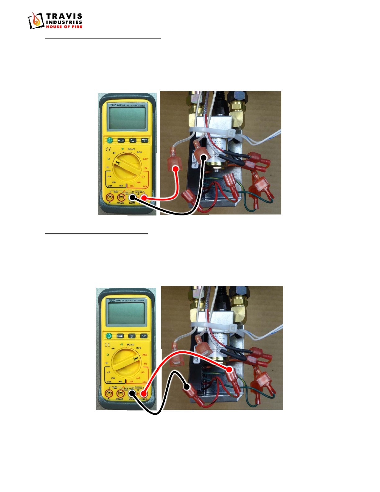
Control Module Wiring Diagram – July 2019 or Later
* NOTE: The thermopile must connect to the control module as shown above (white/orange wire connects
to the white thermopile wire and orange wire connects to red thermopile wire). Do not reverse
the wires. If the wires are reversed, the torch will not work correctly.
Control Module Wiring Diagram – July 2019 or Earlier
* NOTE: The thermopile must connect to the control module as shown above (orange/white wire connects
to the white thermopile wire and orange wire connects to red thermopile wire). Do not reverse
the wires. If the wires are reversed, the torch will not work correctly.
WARNING ATTENTI ON
Here is another sticker with
im por t ant i n f or m at i on t hat you
should also read
UL
GHJH
TravisInd.
Makes nice
Fireplaces
Bl ah bl ah bl ah bl ah
yadda yad da bl ah
blah y adda y adda
How m uch w ood could a woodchuc k
chuck if a w oodchuck could chuck
wood?
He’d chuck as m uch w ood as a
woodchuc k co uld c huck if a
woodchuc k co uld c huck wood.
I have no idea what this sticker says but I will put in this text to
make i t l ook m or e real i sti c. Pl ease m ake su r e you read t he
actual l abe l so you don 't hur t yoursel f.
Thank you f or y our at t e nt i on t o t his i mport ant m at ter .
I have no idea what this sticker says but I will put in this text to
make i t l ook m or e real i sti c. Pl ease m ake su r e you read t he
actual l abe l so you don 't hur t yoursel f.
Thank you f or y our at t e nt i on t o t his i mport ant m at ter .
Why do you never see a
hippopotamu s hiding in a
tree?
Because they are good at it!
What do you do when y ou
see a s pace man?
You park m an!
Red*
White*
White/Orange*
Orange* White/Gree
n
Green
White
Red
White/Red
Black
White/Yellow
Yellow
24VAC Control
Module
1
+
WARNING ATT ENT I O N
Here is anot her s t icker with
import ant inform ation t hat y ou
should also r ead
U
L
GHJH
Travis Ind.
Makesnice
Fireplaces
Blah blah blah blah
yadda yadda blah
blah yadda yadda
How much wood could a woodchuck
chuck if a woodchuck c ould c huc k
wood?
He’d chuck as m uc h wood as a
woodchuck could chuck if a
woodchuck cou ld c huck wood.
I ha v e no idea wha t t his st ick er sa ys but I will put in t his t ext t o
make it look mor e realistic. Please m ak e s ur e y ou r ead t he
actua l label so you d on't hurt your self .
Thank y ou for y our att ention t o this im por t ant m att er .
I ha v e no idea wha t t his st ick er sa ys but I will put in t his t ext t o
make it look mor e realistic. Please m ak e s ur e y ou r ead t he
actua l label so you d on't hurt your self .
Thank y ou for y our att ention t o this im por t ant m att er .
Why do you n ever see a
hippopotam us hiding in a
tree?
Because t hey ar e good at it!
What do you do when you
see a sp ace man?
You par k m a n!
Red*
White*
Orange
*
Orange/White* Green/Yellow
Green
White
Red/Black
Red/Green
Black
White/Blue
White
24VAC Control
Module
1
+

Page.8
17602099‐12/9/2019
How To Test Components
Below you will find details of how to test the individual components of the tempest torch system. This
information is for qualified technicians only.
Gaining Access To Wires At The Torch Head
Totestthecomponentsofthetorchsystemyouwillneedtogainaccesstothewiresunderthetorch
head.Removetheheadfromitsmount(seeinstallationmanualfordetails).Withtheheadremoved,
youwillseeagasvalveandcontrolmoduleandthecontrolwiringallbundledtogetherwithzipties.
Carefullycuttheziptilestogainaccesstothequickconnectswhichwillbethetestingpoints.

Page.9
17602099‐12/9/2019
Testing Continuity Of The Ignitor
Disconnect the two wires from control module (early models – Red/Black and Red/Green –
Current models – Red and White/Red) to the ignitor wires (woven white).
Set multi meter to read Ohms of resistance (Ω).
Touch meter probes to the ignitor wires and take the reading. The ohms reading should be 3.5Ω
+/- .5Ω
Testing Voltage to the Ignitor
Disconnect the two wires from control module (early models – Red/Black and Red/Green –
Current models – Red and White/Red) to the ignitor wires (woven white).
Set multi meter to read AC Volts (VAC).
Touch meter probes to the control modules wires. Turn power on to the torch and take the
reading. The VAC reading should be 24V.
3.5Ω
24V

Page.10
17602099‐12/9/2019
Testing Continuity Of The Valve
Disconnect the two wires from control module (early models – Green/Yellow and Green – Current
models – Green and White/Green) to the ignitor wires (woven white).
Set multi meter to read Ohms of resistance (Ω).
Touch meter probes to the ignitor wires and take the reading. The ohms reading should be
33.2Ω +/- 1.0Ω
Testing Voltage to the Valve
Disconnect the two wires from control module (early models – Green/Yellow and Green – Current
models – Green and White/Green) to the ignitor wires (woven white).
Set multi meter to read AC Volts (VAC).
Touch meter probes to the control modules wires. Turn power on to the torch and take the
reading. The VAC reading should be 24V.
33.2Ω
24V

Page.11
17602099‐12/9/2019
Testing The Output Of The Thermopile
NOTE:Youmayneedanextrasetofhandstohelpwiththistest.Someonewillneedtoholdthetorch
headsothatitcanbeoperated.Makesurenottotouchhotsurfaces.
Make sure the two wires from control module (early models – Orange/White and Orange –
Current models – Orange and White/Orange) connected to the Thermopile wires (Red and
White).
Make sure the solid colored wire from the module is connected to the RED wire from the
thermopile. Polarity matters, so if this is not correct, change the wires so they are correct.
Set multi meter to read DC millivolts (DC mV).
Touch meter probes to the crimps. Turn the torch on, wait for the flame to light, and then take the
reading. The DC mV reading should be above 50 mV.
The control module determines the state of the torch (fire or no fire) by looking at the
percentage of voltage change from the thermopile (gain or loss - not a set voltage). If
no fire is sensed by the control module, the igniter and gas valve will stay on for the
full ignition sequence (approximately 35 seconds), after which they will close.
>50mV

Page.12
17602099‐12/9/2019
Wiring Multiple Torches to One Transformer
The manner in which you wire the torches to the transformer affects the maximum length of wire and wire gauge. Make
sure to determine the wire configuration before installation. NOTE: You may use both direct-run and daisy-chain
configurations.
Polarity must be maintained in all multiple torch installations. Failure to
maintain polarity will result in damage to the control module.
Daisy-Chain Example
Direct-Run Example
WAR N ING ATT E NT ION
1
Hot (Black)
Common (White)
Gr ound (Gr een)
P
o
w
e
r
S
u
p
p
l
y
(GFCI Protected)
WA R N ING ATTENT ION
1
Hot (Black)
Common (White)
Ground ( Green)
P
o
we
r
S
u
pp l
y
(GFCI Protect ed)

Page.13
17602099‐12/9/2019
Daisy-Chain Wire Length Chart
This type of wire configuration allows for torches to be wired in a series, reducing the amount of wire
used. Use the charts below to determine the correct wire gauge and length. In the example below, the
transformer has 3 torches on one branch.
How to Calculate Wire Length: Add together all of the wire length(s) used for the entire installation. If
you have one 80’ length and three 20’ lengths, your wire length would be 140’.
24 Volt Lead # Of Torches On Branch
Wire 2 3 4 5 6
14 G min 0' 0' 0' 0' 0'
max 113' 71' 49' 37' 28'
12 G min 0' 0' 0' 0' 0'
max 173' 108' 75' 55' 43'
10 G min 0' 0' 0' 0' 0'
max 266' 165' 115' 85' 65'
26 Volt Lead* # Of Torches On Branch
Wire 2 3 4 5 6
14 G min 27' 10' 1' 0' 0'
max 184' 118' 85' 65' 51'
12 G min 41' 16' 2' 0' 0'
max 281' 179' 129' 99' 79'
10 G min 63' 23' 3' 0' 0'
max 432' 276' 198' 151' 121'
28 Volt Lead* # Of Torches On Branch
Wire 2 3 4 5 6
14 G min 104' 62' 40' 27' 19'
max 242' 157' 113' 88' 71'
12 G min 160' 94' 61' 41' 28'
max 369' 238' 173' 134' 108'
10 G min 245' 144' 93' 63' 43'
max 566' 366' 266' 206' 165'
* Not available on some transformers.
WAR N ING ATTE NT ION
1
Hot (Black)
Com mon (White)
Gr ound ( Gr een)
P
o
w
e
r
S
u ppl
y
(GFCI P rotected)

Page.14
17602099‐12/9/2019
Replacement Parts
Part # Description Diagram #
250-01800 SCW, PHMS M4 x 20mm PK OF 6# 2
250-04553 CONTROL MODULE 3
250-04554 GAS CONTROL VALVE 4
250-04552 CONTROL MODULE ASSEMBLY, TEMPEST 6
250-04610 BRN SYSTEM ASSY, TMP(EI) LP 7
250-04609 BRN SYSTEM ASSY, TMP(EI) NG 7
250-04550 THERMOPILE, TEMPEST 8
250-04549 IGNITER, TEMPEST 9
250-01799 THUMB SCREW, TEMPEST TORCH 11
250-01445 GLASS RETAINER (TEMPEST) 1 EACH 12
250-01790 FLAME SPREADER w/PYRMD- NG 13
250-01791 FLAME SPREADER w/PYRMD - LP 13
250-01256 RAIN CAP ASS'Y, TEMPEST 14
250-01257 VERTICLE ROD w/SCRWS, TEMPEST 15
250-01251 GLASS – TEMPEST 16
250-04611 STOVE PACK, TEMPEST ELCTRC IGN
250-01789 BALL VALVE, (SHUT-OFF) TEMPEST
250-04612 MANUAL
3
4
Other manuals for Tempest Portable Torch
2
Table of contents
Other Travis Industries Outdoor Light manuals
Popular Outdoor Light manuals by other brands

SunSetter
SunSetter Somfy TaHoma Assembly, installation and operation instructions

Heitronic
Heitronic 500655 Installation and operating instructions

Portfolio
Portfolio 00605 quick start guide

Quoizel
Quoizel LDG8406K Assembly instruction sheet

Quoizel
Quoizel TRE8409K Assembly instruction sheet

Saxby
Saxby 13822 instruction manual

Hess
Hess 10.08511.4000 Installation and operating instructions

Lake Lite
Lake Lite LL-SDL-WAVE quick start guide

iGuzzini
iGuzzini iTEKA manual

JONATHAN Y
JONATHAN Y JYL1088A quick start guide

Architectural Area Lighting
Architectural Area Lighting PROS Providence Small installation guide

Fermob
Fermob HOOP L1200 manual