ELECTRONIC SPEED CONTROL ADJUSTMENT
1. Install new or fully charged batteries in the transmitter.
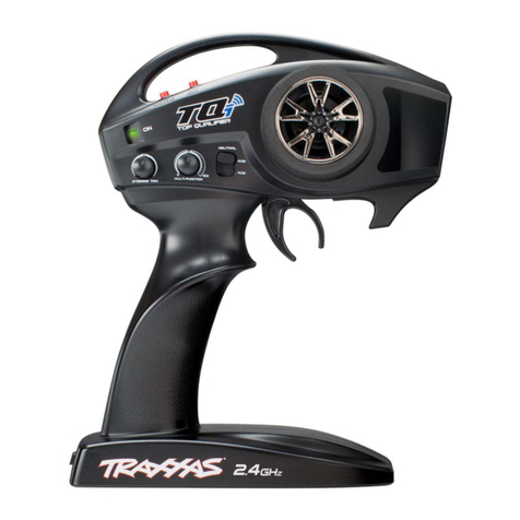
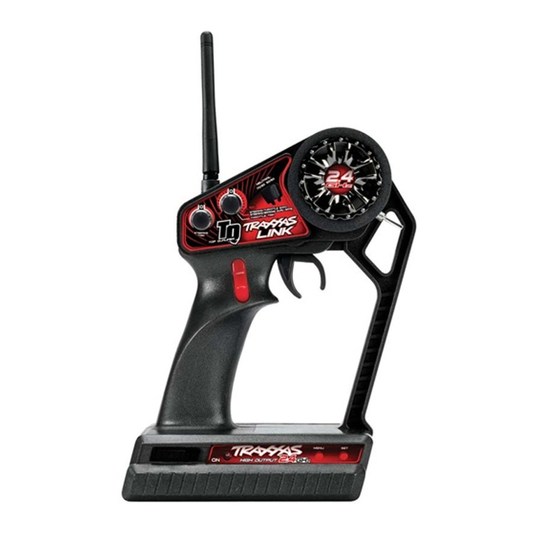
2. Set the transmitter throttle trim control to the center neutral position.
3. If your transmitter is equipped with an adjustment to vary the amount of
throttle trigger travel, set it to have the same amount of travel when you move
the throttle control forward or back. On Traxxas transmitters, set the throttle
neutral adjust to the 50/50 position.
4. Set the model up and anchor it so that the driven wheels are off the ground or
the propeller is free to spin.
5. Turn the transmitter on and then plug a freshly charged battery pack into the
speed control.
6. The Traxxas electronic speed control has two adjustments: the neutral control
and the proportional control. Use a small screwdriver to adjust the controls.
CAUTION: The adjustment controls will only turn 1/4 turn left or right
from center. Do not turn the controls past their stops or they will
break. Use a light touch when making adjustments. Controls damaged
by overturning them past their stops will not be covered under
the warranty.
Adjusting the Neutral Control - If the model’s motor started running when you
plugged in the battery pack, gently turn the neutral control right or left until the
motor stops running and the L.E.D. is off (neither green or red).
Adjusting the Proportional Control - After setting the neutral control, move the
throttle lever or trigger on the transmitter to full throttle. Now, carefully adjust the
proportional control right or left until the motor is running at its fastest speed and
there is a strong, solid green light emitted from the L.E.D. If the L.E.D. is shining red
at full throttle, then switch the throttle servo reversing switch on the transmitter
and readjust. The L.E.D. must show green at full throttle in order for the speed
control to work properly.
IMPORTANT:
Always turn the transmitter on first, before you connect the battery pack in
your electric model. If you do not, the model will operate erratically and
appear to malfunction. (Remember, the transmitter is on first and off last.)
PRECAUTIONS:
Excessive heat is the main enemy to your speed control. Excessive heat, which is
built up from the improper installation and use of an electronic speed control is
the number one cause of failure. By being attentive to the performance and care
of your model, you can be assured trouble-free operation.
Do not overload your speed control. The harder your motor has to work, the
more current (amps) is drawn through the speed control. As the current draw
increases, so does the heat built-up. Here are some tips to prevent overloading
your XL-1.
Be sure that your model is not over-geared. Symptoms of over-gearing include
an extremely hot motor, hot batteries, short run time, an extremely hot speed
control, and sluggish acceleration. If you experience any of these symptoms, try
using a smaller pinion gear on the motor. The other danger of being over-geared
is that it can lead to premature motor failure. When an overworked motor fails, it
can become a short circuit and severely damage your XL-1.
If your model encounters an obstacle which it cannot pass, or becomes trapped
in deep sand, do not continue to run the model. This will prevent damage to the
motor and speed control. Return the transmitter controls to their neutral position
and then free the model.
Get into the habit of periodically checking the temperature of your electronic
components. If any of them are too hot to touch, especially the speed control,
do not continue to run your model. Wait a few minutes for everything to cool
down before continuing.
The radio system is not waterproof. Avoid driving through puddles, wet grass,
▼ ▼ ▼ ▼ ▼ ▼
STOP STOP
1
/
4
Turn
1
/
4
Turn
Center
ELECTRONIC SPEED CONTROL
PROPORTIONAL
NEUTRAL
or mud. For marine applications, protect the speed control from submersion
or standing water inside the boat. If water gets into the electronics, it could
damage them.
Do not continue to operate the model with low batteries or you could lose
control. Indications of low battery power include: slow operation, sluggish servos
and, for Traxxas transmitters, a flashing red light. When using nicad batteries, be
especially alert for signs of weak batteries, stop immediately at the first sign of
weak batteries.
With the XL-1 speed control do not use modified motors with fewer than 18-turns
of wire. More powerful motors increase current flow through the electronics and
could damage them. When using high-performance motors, make sure that
cooling air can pass over the heat sinks.
Allow the speed control to cool down between battery packs to ensure
correct operation and long life.
LIMITED ELECTRONICS WARRANTY
Traxxas warrants your Traxxas electronic product to be free from defects in
materials or workmanship for a period of thirty (30) days from the date of purchase.
During the warranty period, please send the defective unit, along with your proof of
purchase indicating the date purchased, your return address, a daytime phone
number and a brief description of the problem to:
TRAXXAS
1100 KLEIN ROAD
PLANO, TEXAS 75074
If the component is found to be defective, it will be repaired or replaced at no
charge. THIS WARRANTY DOES NOT COVER DAMAGE DUE TO CARELESSNESS,
MISUSE, NEGLECT OR ABUSE. Traxxas makes no other warranties, expressed or
implied. TRAXXAS shall not be liable for any indirect, incidental, or consequential
damages arising out of the assembly, installation or use of this product. This
warranty gives you specific legal rights, you may have other rights which vary
from state to state. You are required to complete and return the enclosed
REGISTRATION CARD as a condition of the coverage and performance of
this warranty.
THE TRAXXAS EXTENDED SERVICE PLAN
FOR ELECTRONIC COMPONENTS
After the expiration date of the warranty period, Traxxas will repair electronic
components for a flat rate of $15.00 plus $5.00 for shipping and handling. The
products covered by this extended service plan include electronic speed controls,
transmitters, receivers, servos and battery chargers (motors and mechanical speed
controls are not covered). Other mechanical repairs will be estimated on an
individual basis. The covered repairs are limited to non-mechanical components
which have not been subjected to abuse, misuse or neglect. The separate enclosed
form must be filled out completely and enclosed along with the product to
be repaired.
Return the unit(s) with a brief note describing the problem, plus a daytime phone
number and return address to:
TRAXXAS
1100 KLEIN ROAD
PLANO, TEXAS 75074
For technical assistance, call 1-888-TRAXXAS (888-872-9927)
For orders & other information,
call (972) 265-8000 or fax (972) 265-8011
▼ ▼ ▼
