Trekkrunner GM-280 User manual

NOTE:
Please read all instructions
carefully before using this
product
Model No.:
GM-280
Retain This
Manual for
Reference
OWNER'S
MANUAL
Power Bench
Part A

TABLE OF CONTENTS
BEFORE YOU BEGIN...................................................................................………………1
IMPORTANT SAFETY NOTICES..................................................................………………2
HARDWARE IDENTIFIER.....…....................................................................……………….3
ASSEMBLY INSTRUCTIONS........................................................................………………5
EXPLODED DIAGRAM…………………………………………………………………….…….11
PARTS LIST...............................................................................................…………………12
ORDERING PARTS.......................................................................................………………13
BEFORE YOU BEGIN
Thank you for selecting the GM-280 Power Bench. For your safety and
benefit, read this manual carefully before using the machine. As a
manufacturer, we are committed to provide you complete customer
satisfaction. If you have any questions, or find there are missing or damaged
parts, we guarantee you complete satisfaction through direct assistance from
our factory.
1

IMPORTANT SAFETY NOTICE
PRECAUTIONS
This exercise machine is built for optimum safety. However, certain precautions apply
whenever you operate a piece of exercise equipment. Be sure to read the entire manual
before you assemble or operate your machine. In particular, note the following safety
precautions:
A. Keep children and pets away from the machine at all times. DO NOT leave children
unattended in the same room with the machine.
B. Only one person at a time should use the machine.
C. If the user experiences dizziness, nausea, chest pain, or any other abnormal symptoms,
STOP the workout at once. CONSULT A PHYSICIAN IMMEDIATELY.
D. Position the machine on a clear, leveled surface. DO NOT use the machine near water or
outdoors.
E. Keep hands and feet away from all moving parts.
F. Always wear appropriate workout clothing when exercising. DO NOT wear robes or other
clothing that could become caught in the machine. Running or aerobic shoes are also
required when using the machine.
G. Use the machine only for its intended use as described in this manual. DO NOT use
attachments not recommended by the manufacturer.
H. Do not place any sharp object around the machine.
I. Disabled person should not use the machine without a qualified person or physician in
attendance.
J. Before using the machine to exercise, always do stretching exercises to properly warm up.
K. Never operate the machine if the machine is not functioning properly.
L. A spotter is recommended during exercise.
CARE AND MAINTENANCE
M. Lubricate moving parts with WD-40 or light oil periodically.
N. Inspect and tighten all parts before using the machine.
O. The machine can be cleaned using a damp cloth and mild non-abrasive detergent. DO NOT
use solvents.
P. Maximum weight capacity on the flat position: 130Kgs (Including bar and weights).
Q. Maximum weight capacity on the inline position: 120Kgs (Including bar and weights).
R. Maximum weight capacity on the decline position: 120Kgs (Including bar and weights).
S. Maximum weight capacity on the leg developer: 40kgs (Including bar and weights).
T. Maximum user’s weight: 110kgs.
WARNING: BEFORE BEGINNING ANY EXERCISE PROGRAM, CONSULT YOUR
PHYSICIAN. THIS IS ESPECIALLY IMPORTANT FOR INDIVIDUALS OVER THE AGE OF
35 OR PERSONS WITH PRE-EXISTING HEALTH PROBLEMS. READ ALL
INSTRUCTIONS BEFORE USING ANY FITNESS EQUIPMENT. We ASSUME NO
RESPONSIBILITY FOR PERSONAL INJURY OR PROPERTY DAMAGE SUSTAINED BY
OR THROUGH THE USE OF THIS PRODUCT.
SAVE THESE INSTRUCTIONS.
2
HARDWARE IDENTIFIER

NOTE: The following parts are not drawn to scale. Please use your own ruler to measure the size.
3

4

ASSEMBLY INSTRUCTION
Tools Required Assembling the Machine: Two Adjustable Wrenches and Allen
Wrenches
NOTE: It is strongly recommended two or more people assembling this machine to
avoid possible injury. Do not tighten all the bolts and nuts until getting instruction.
STEP 1 (See Diagram 1)
A Attach the upright beam (#2) to the front stabilizer (#1), and secure them horizontally
with two M10×70mm Carriage bolts (#31), two Ø10mm washers (#38), two M10 aircraft
nuts (#40).And then secure them vertically with two M10×20mm Allen bolt (#34), two Ø
10mm Washers (#38).
5
STEP 2 (See Diagram 2)
DIAGRAM 1

A Attach another end of the Seat pad Support frame (#3) to the upright beam (#2) and
secure them with two M10×63mm Carriage Bolts (#30), two Ø10mm washers (#38), two
M10 aircraft nuts (#40).
B Attach the one end of the seat pad support frame (#3) to the rear stabilizer (#4).
Secure them with two M10×90mm carriage bolts (#29), one flat connection (#11), two
Ø10mm Washers (#38), two M10 aircraft nuts (#40) .DO NOT tighten the bolts yet.
C. Attach one end of the bracket (#10) to the upright beam (#2), and secure them with one Ø
10mm Washer (#38), one M10×20mm Allen bolt (#34). Attach the other end of the bracket to
the seat pad support frame (#3), secure them with One M10×70mm carriage bolt (#31), Ø
10mm washer (#38), One M10 aircraft nut (#40).
6
DIAGRAM 2

STEP 3 (See Diagram 3)
A Attach the leg developer (#5) to the upright beam (#2). Secure them with one M10×
80mm allen bolt (#42), two Ø10mm washers (#38), one M10 Aircraft nut (#40).
B Insert two foam roll tubes (#12) halfway through the holes on the leg developer. Push
four foam rolls (#26) onto the tubes from both sides and push the four Ø25×1.3mm
end caps (#20) to the foam roll tubes (#12).
CPlace a sleeve (#18) and a spring clip (#28) onto the weight post on the leg developer.
Attach the handle (#6) to the leg developer (#5), and secure them with Ø10×100
pin(#23).
DIAGRAM 3
7
STEP 4 (See Diagram 4)
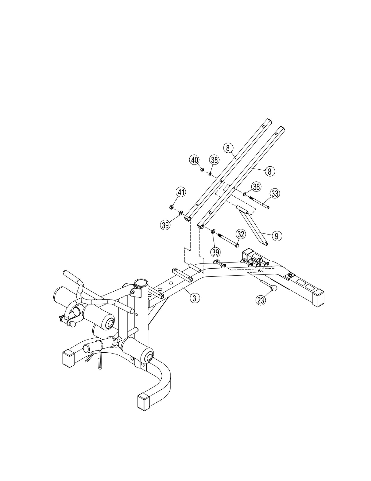
A Attach the backrest pad support (#8) onto the seat pad support frame (#3), align the
holes and secure them with one M12×145mm Hex bolt (#32) and two Ø12mm washers
(#39), one M12 Aircraft nut (#41).
B Attach the backrest pad incline support (#9) to the backrest pad support (#8), and
secure them with one M10×145mm Allen Bolt (#33), two Ø10mm washers (#38), one
M10 aircraft nut (#40).
DIAGRAM 4
8

STEP 5 (See Diagram 5)
A Attach the seat pad (#14) onto the seat pad support frame (#3), align the holes secure them
with four M8×40mm allen bolts (#35) and four Ø 8mm washers (#37).
B Attach the Bracket pad (#13) to the backrest pad supports (#8), align the holes and
secure them with four M8×40mm allen bolts (#35) and four Ø8mm washers (#37).
DIAGRAM 5
9

STEP 6 (See Diagram 6)
A Insert the arm curl pad support (#7) to the hole of upright beam (#2), and secure them
with M10×90mm Lock pin (#17) to adjust different height.
B Attach the arm curl pad (#15) to the arm curl pad support (#7), and secure them with two
Ø8mm washers (#37), two M8×16mm allen bolts (#36).
C Tighten all the bolts and nuts when finishing assembling.
DIAGRAM 6

10
Exploded Diagram

11
PARTS LIST
Key
No.
Description
QTY
Key
No.
Description
QTY
1
Front stabilizer
1
27
Ø18×Ø10×12 bushing
2
2
Upright beam
1
28
Ø49 spring clip
1
3
Seat pad support frame
1
29
M10×90mm Carriage bolt
2
4
Rear stabilizer
1
30
M10×63mm Carriage bolt
2
5
Leg developer
1
31
M10×70mm Carriage bolt
3
6
Handle
1
32
M12×145mm Hex bolt
1
7
Arm curl pad support
1
33
M10×145mm Allen bolt
1
8
Backrest pad support
2
34
M10×20mm Allen bolt
3
9
Backrest pad incline support
1
35
M8×40 mm Allen bolt
8
10
Bracket
1
36
M8×16mm Allen bolt
2
11
Flat connection
1
37
Ø8 washer
10
12
Foam roll tube
2
38
Ø10 washer
14
13
Bracket pad
1
39
Ø12 washer
2
14
Seat Pad
1
40
M10 Aircraft nut
9
15
Arm curl Pad
1
41
M12 Aircraft nut
1
16
Ø25×2 end cap
1
42
M10×80 mm Allen bolt
1
17
M10×90 lock pin
1
43
Ø50×1.5 End cap
3
18
Ø50×Ø26.5×200 mm sleeve
1
4# Allen Wrench
1
19
End cap
4
5# Allen Wrench
1
20
Ø25×1.3mm end cap
4
6# Allen Wrench
1
21
□25×2 End cap
4
22
Ø76×60 Sleeve
1
23
Ø10×100 Pin
2
24
Ø32 bushing
2
25
Ø25×130 grip
2
26
Ø22×Ø100×180 foam roll
4
12
Other manuals for GM-280
1
Table of contents
Other Trekkrunner Fitness Equipment manuals


