Tres 900 User manual

IlliGid
I
nsta
ll
at
i
on
G
u
id
e

Shipping Box Contains
Shipping
Box
Contains
Ever
y
thin
g
that is included in the box bein
g
shi
pp
ed to a
yg
g
pp
customer should contain the following items:
•Bracket Assembly
•Reader Assembly
•Power Supply ‐tres‐PSS12‐035
•
Documentation
on
CD
ROM
•
Documentation
on
CD
ROM
•Printed Documentation (Quick Start Guide and a checklist)
Everything
will
be
securely
inserted
inside
the
box
so
items
do
Everything
will
be
securely
inserted
inside
the
box
so
items
do
not shift during shipping and handling. We pay special attention
to the bracket assembly.
RevC2

tres900 CD
tres900
CD
•\CoolTerm
–Coolterm.exe:freewareterminalprogram(likeHyperTerminal)
•\Documents
tres900 Quick Start Guides tres900 Operations Manual tres900
–
tres900
Quick
Start
Guides
,
tres900
Operations
Manual
,
tres900
ReaderSpecification,etc.
•\Drivers
–ZNetCom2.exe:Ethernetinstallationdriver
•\Fliers
–
Sales brochures for the product
–
Sales
brochures
for
the
product
•\Utilities
–Treslevel.exe:Readeroutputpowercontrolprogram
RevC3

Electromagnetic Interference
Electromagnetic
Interference
Transmission line‐related radio‐frequency interference is the indirect
effects
of
transmission
line
and
is
prod ced
b
the
ph sical
interactions
effects
of
transmission
line
and
is
prod
u
ced
b
y
the
ph
y
sical
interactions
of line electric fields. The electromagnetic interference or EMI created
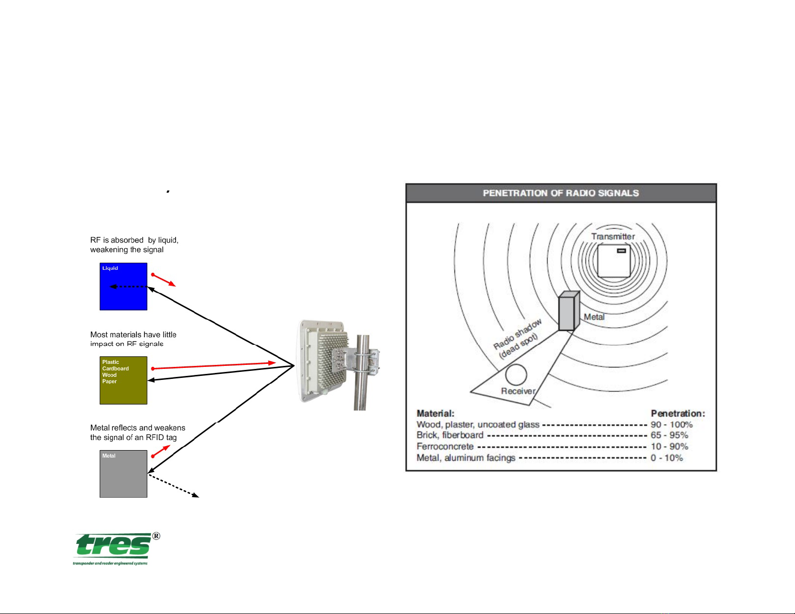
by power transmission lines can interfere with radio waves. This can
lt
i
it f
ith
RFID
di
d
ll
h
il
Bth
resu
lt
i
n
i
n
t
er
f
erence w
ith
RFID
,ra
di
o, an
d
ce
ll
p
h
one s
i
gna
l
s.
B
o
th
electricity and RF used to transmit data vibrate at certain frequencies.
The electrical effects of transmission lines can be reduced through
hld
b
h
l
ll
s
h
ie
ld
ing or
b
urying t
h
e transmission
l
ines. Contact your
l
oca
l
power
company for assistance in suppressing EMI.
RevC4

RFID Obstructions
RFID
Obstructions
Be sure
y
our readers have a
y
clear view of any tags.
RevC5

Cable Guide
Cable
Guide
Selecting the correct wire will enhance the performance and
reliability o
f
your system. The size o
f
thewiremustbelarge
enough to carry the maximum current expected without undue
voltage
losses
.
All
wire
has
a
certain
amount
of
resistance,
this
voltage
losses
.
All
wire
has
a
certain
amount
of
resistance,
this
resistance causes a drop in the voltage from the source to the
load. The wire guide provides the minimum wire size needed to
limit
voltage
drops
to
5
%
at
a
given
distance
in
a
12
V
system
limit
voltage
drops
to
5
%
at
a
given
distance
in
a
12
V
system
.
RevC6

Power Requirements
Power
Requirements
The Reader can be powered from 8 to 16 volts DC (1.5A @ 12V)
ld
li
ihi
Th
Rd
hld
regu
l
ate
d
,
li
near or sw
i
tc
hi
ng power sources.
Th
e
R
ea
d
er s
h
ou
ld
be operated from a grounded supply that has the same ground
reference as the host.
RevC7

Power Requirements
Power
Requirements
The recommended
p
ower su
pp
l
y
is the tres‐PSS12‐035: Power
p
pp y
Supply, 85‐264VAC, 35W, 12VDC @ 3A regulated, which is
suppliedwitheachReader.TheReaderunitWarrantyisbased
on
its
use
Caution
:
Wiegand
Output
use
GREEN
wire
for
Data
0
on
its
use
.
Caution
:
Wiegand
Output
use
GREEN
wire
for
Data
0
and YELLOW wire for Data 1.
RevC8

Mountin
g
Reader
g
The mounting bracket is designed specifically for mounting the
tres900 Reader. The Reader could be installed on a
p
ole or on
p
wood, concrete, or brick structures and aim the antenna toward
the zone of desired coverage. The Figure below shows how the
bracket
looks
assembled
on
a
2
in
OD
round
pole
The
tool
of
bracket
looks
assembled
on
a
2
in
OD
round
pole
.
The
tool
of
choice is a 3/8” (10 cm) wrench.
RevC9

Read Zone &Mounting Technique
Read
Zone
&
Mounting
Technique
D
ARMING / ENTRY LOOP
RevC10

Parallel Surfaces Rule
Parallel
Surfaces
Rule
Passive RF tag actually gets its’ power from the reader. That is to
h
h
d
i
ii
RF
d
h
b
bl
say t
h
at, t
h
erea
d
er
i
sem
i
tt
i
ng
RF
an
d
t
h
etagmust
b
ea
bl
eto
absorb that RF, accelerate the signal and the reflect it back to the
reader. Therefore, i
f
the surface o
f
the reader and tag are close
to parallel, this principal will result in better tag reads. Below is
an example of this rule not being followed:
I
thi
it
th
ft
th t
hi l
I
n
thi
s
i
ns
t
ance,
th
e
f
ac
t
th
a
t
ve
hi
c
l
es
were turning through the read zone
meant poor performance when the
reader was mounted on the white post.
Once the reader was moved back closer
to
the
operator,
it
worked
much
better!
RevC
to
the
operator,
it
worked
much
better!
11

Tag Orientation
‐
Vertical Plane
Tag
Orientation
Vertical
Plane
Vertical orientation is desired, aim the antenna at a spot down
the road from the gate where you want to start reading tags.
From this spot forward, the detection area will increase as you
get closer to the gate. The tags must be vertically oriented for
optimum read range. The Windshield tag must be mounted on
windshield glass for optimum read range.
RevC12

Tag Vehicle Installation
Tag
Vehicle
Installation
Ensure the Tag is mounted in a vertical position for optimum
read range. Windshield sticker should be 2 inches away from any
metal posts on all sides. Prior to installation, make certain the
desired location complies with all state and local vehicle codes/
laws. Caution: some windshield contain metal so an exterior tag
should be used.
RevC13

Wiegand Output
Wiegand
Output
Standard Wiegand protocol; Data 0 (GREEN wire) and Data 1
(
YELLOW
i)
ll
i
5
l
d
i
(
YELLOW
w
i
re
)
norma
ll
yrest
i
ng at +
5
vo
l
ts an
d
mov
i
ng to zero
voltage (GRAY wire ‐Ground) on logic 0 or logic 1.
Shielded
(
22
AWG
for
≤
25
’
and
16
AWG
up
to
500
’
per
Wiegand
Shielded
(
22
AWG
for
≤
25
and
16
AWG
up
to
500
per
Wiegand
specification) insulated, stranded wire is recommended.
RevC14

Serial Output (RS232)
Serial
Output
(RS232)
This is a standard RS232 Serial interface that can be read by any
h
RS
232
ii
Th
Rd
ill
computer t
h
at accepts
RS
232
commun
i
cat
i
ons.
Th
e
R
ea
d
ers w
ill
output data through simultaneous output ports and can be
monitored with a terminal program that displays ASCII data.
RevC15

Trigger Function
Trigger
Function
If the Reader is configured for triggering mode, the reader will
only
read
a
tag
when
the
BLUE
trigger
wire
(T
1
)
is
tied
to
ground
only
read
a
tag
when
the
BLUE
trigger
wire
(T
1
)
is
tied
to
ground
.
Normal ways to accomplish this is by using a Loop Detector or
the preferred detection system is the tres Smartloop to detect
the
presence
of
a
vehicle
to
open
a
gate,
or
as
a
safety
device
to
the
presence
of
a
vehicle
to
open
a
gate,
or
as
a
safety
device
to
prevent the gate from closing on a vehicle in its path.
ARMING / ENTRY LOOP
RevC16

Terminal Program Setting
Terminal
Program
Setting
The default communication settings are 9600, 8, N, 1. Execute
hi
fil
HTil
i
id
PC
t
hi
s
fil
eso
H
yper
T
erm
i
na
l
can open
i
naw
i
n
d
ow on your
PC
.
Upon powering the Reader you should see a start up message
displayed to your screen, this indicates the Reader has
performed a self test and is ready to be operated. You are now
ready to read Tags and have them reported to your PC.
RevC17

Power Level Control
Power
Level
Control
TheprogramintheCDcalled“treslevel.exe”isahandyutility
thatallowsyoutocontroltheoutputpoweroftheReader.What
thismeansisifyouaregetting30’readrangebutonlywant15’,
thenchangetheOutputLevelfrom30.0dBm to20.0dBm.Once
installedyouconnectyourReadertothePCviaRS232portand
runthisprogram.
RevC18

Tag Programmer
Tag
Programmer
The tres900 has a tag Programmer and software package that
allows our factory and you to program 26 bit Wiegand data to
any EPC Gen2 inlay/credential ….. Including custom programming
of
our
tags/credentials
of
our
tags/credentials
RevC19

Troubleshooting Guide
Troubleshooting
Guide
Q: Toconfirmthattheunitisoperatingproperly
f h b dbl h d d h
–
Con
f
irmt
h
e
b
eeperisau
d
i
bl
ew
h
enagoo
d
tagispresente
d
orw
h
enpoweris
firstapplied.Ifitisnot,removepower.
–CheckthattheRED andBLACK wiresareinstalledcorrectly
Che k the olta e at the Reader pi tail
able
if onder abled the olta e
–
Che
c
k
the
v
olta
g
e
at
the
Reader
pi
g
tail
c
able
,
if
y
o
uu
nder
c
abled
the
v
olta
g
e
dropwouldbetoomuchtopoweruptheReader.
Q: Readerjustbeepsandkeepsbeeping,about3xpersecond
–
Not enough power from the power supplier Insufficient power
–
Not
enough
power
from
the
power
supplier
,
Insufficient
power
,
–CheckthevoltageattheReaderpigtailcable,ifyouundercabledthevoltage
dropwouldbetoomuchtopoweruptheReader.Verifythevoltagesuppliedto
theReaderisbetween8and16VDC
Q: Readerdoesnotrecognizeatag(nobeep,nooutputtedtagdata)
–Ifnobeep,checktoseeifanothertagworks,maybedamagedtag.VerifyReader
operationsbyconnectingtoacomputerthroughtheRS232portandrunninga
RevC
Terminalprogram.
20
Other manuals for 900
1
Table of contents
Popular RFID System manuals by other brands

Crestron
Crestron RFID-USB quick start

iDTRONIC
iDTRONIC BLUEBOX ADVANT UHF manual

AXEM Technology
AXEM Technology Atid AT188N user guide

Elatec
Elatec TCPConv Technical manual

Feig Electronic
Feig Electronic OBID classic-pro ID CPR.04.P/AB-USB Montage, installation

Omron
Omron DeviceNet V680-HAM42-DRT user manual