Tri-Clover Tri-Blender F1114L User manual

TBSM
Tri-Clover®
Tri-Blender
Models F1114L • F2114 • F2116 •
F2116-EZ System • F3218 • F4329

2

3

4
CONTENTS
ThankyouforpurchasingaTri-CloverProduct!
This manual contains installation, operation, cleaning and repair instructions, with parts lists, for models
F1114L,F2114,F2116,F2116-EZ-system,F3218andF4329 Tri-BlendersmanufacturedbyTri-Clover,
Inc., Kenosha, Wisconsin. It also provides a troubleshooting chart to assist in determining blender
malfunction.
READ THIS MANUAL
carefully to learn how to service the Tri-Blender.Failure to do so could result in
personalinjuryorequipmentdamage.
SAFETY
IMPORTANTSAFETYINFORMATION ............................................................................................ 5
INTRODUCTION
DESCRIPTION ................................................................................................................................6
BASICOPERATION ........................................................................................................................ 6
INSTALLATIONGUIDELINES .......................................................................................................... 7
INSTALLATION
PIPING HINTS................................................................................................................................. 8
CLEANING .................................................................................................................................... 10
MAINTENANCE
DISASSEMBLY ............................................................................................................................. 11
REASSEMBLY............................................................................................................................... 16
SETTING THE DRIVE COLLARAND SEALREPLACEMENT ....................................................... 20
TROUBLESHOOTING
TROUBLESHOOTINGGUIDELINES ............................................................................................. 22
PARTS LIST
MODELF1114LANDF2114 SYSTEM .......................................................................................... 24
MODELF2116ANDF2116 EZ-SYSTEM....................................................................................... 26
MODELF2116-EZSYSTEM.......................................................................................................... 27
MODELF3218 ............................................................................................................................... 28
MODELF4329 ............................................................................................................................... 30

5
IMPORTANT SAFETY INFORMATION
SAFETY
DANGER
WARNING
Indicates an imminently hazardous situation which, if not
avoided,
will
result in death or serious injury. The word
Danger is used in the most extreme cases.
Indicates a potentially hazardous situation which, if not
avoided,
may
result in minor or moderate injury. May
also be used to alert against an unsafe operating or
maintenance practice.
CAUTION
Indicates a potentially hazardous situation which, if not
avoided,
could
result in death or serious injury.
Safety is very important!
DO NOT attempt to modify any Tri-Clover product.
To do so could create unsafe conditions and
void all warranties.
DO NOT place any Tri-Clover product in an application where general
product service ratings are exceeded.
The following DANGER, WARNING, AND CAUTION signs and their meanings are used within these
instructions.
Safety labels are placed on every Tri-Blender. Do not remove any labeling on any Tri-Clover product.
Immediately replace any label that is missing.
Part Number 38-241

6
INTRODUCTION
The Tri-Blender consists of two basic sections, the dry material section and the liquid material section.
TheTri-Blendermodels F3218 and F4329 aremountedonbases. Thesemodelsare mounted adjacent
to the drive motor and are driven by belts running between pulleys under the base. The electrically
controlled Butterfly valve is standard equipment on model F3218. The F4329 is standard without a
valve or hopper. The control panel may be mounted directly to the Tri-Blender base or may be mounted
in remote areas to suit your facility.
TheTri-Blendermodels F1114L, F2114 and F2116 aremountedon a base directly above theelectric
drive motor. The drive motor is mounted to the underside of the base. It is coupled to the blender by
the motor shaft which extends through the base into the stub shaft that is secured to the impeller.
This model is equipped with a hand operated butterfly valve for control of the material entering the
blender. Optional electrically or pneumatically controlled valves are also available.
Blender F2116 EZ-System is the same as units F1114L, F2114 and F2116 with additions of a dolly,
tube assembly, motor starters and supply pump. For supply pump service information, refer to the
Tri-Clover
"C"SeriesCentrifugal Pump Service Manual
.
On all models, the connection ends, the diffuser and the suction tube, the inlet adapter, the casing,
screen, washer, and backplate are made of 316 stainless steel. The hopper is made of 304 stainless
steel. All of the tubes are fastened with quick couple Tri-Clamps for easy care and fast access. The
fourlegssupporting the Tri-Blenders are adjustablefor easy leveling of theblenderduring installation.
DESCRIPTION
BASIC OPERATION
The Tri-Blender basically consists of a centrifugal pump
head and impeller mounted so that the normal suction port,
or inlet, is pointed upward. The inlet piping consists of a
patentedtube-within-a-tubearrangement. Thisservesto
keepthe liquid and dry ingredients separated until they are
inthemixingchamber. Thetube-within-a-tubearrangement
eliminatesprewetting,oneof the major problems of wet-dry
mixing.
The natural suction of a centrifugal pump is used to pull the
powderfromthehopperthroughthediffusertube.
The outer tube is used to direct the liquid into the impeller.
The liquid is introduced at the leading edge of the impeller
bladeswherethepressuregradient of the Blender head is
zero. Since there is no suction at this point, liquid must be
pumped to the blender by external means, such as the
supplypump.
The liquid inlet is mounted tangentially. The liquid entering
theblender mixing chamber entersthe chamber in the
same direction the impeller is rotating. The impeller then
strikes the liquid and accelerates it, with minimal splashing. This is how the powder inlet tube can be
keptdryduringoperation.
In operation, the liquid pumped into the Blender is accelerated outward until it strikes the blender
screen. This creates a natural back pressure that causes the liquid to flow downward and back toward
the eye of the impeller. This forms a hollow envelope into which the powder is introduced by the natural
suction of the blender.
Hopper
Valve
Diffuser
Tube
Liquid
Inlet
Outer
Tube
Area
Impeller
Outlet
Screen
Blending
Chamber

7
INSTALLATION
INSTALLATION GUIDELINES
UNPACKING EQUIPMENT
When unpacking your equipment, inspect all of the contents for damage that may have occurred during
shipping. Report any damage to the carrier.
LOCATION AND INSTALLATION
The Tri-Blender unit should be located within 3 feet (1 meter) of the liquid source for best performance
and in a position where the supply piping can be short and direct with a minimum number of elbows and
fittings. The liquid to the blender must be supplied by an auxiliary source. In certain applications, a
dischargepumpmayalsoberequired. Contact Tri-Clover for recommendations on supply and
discharge pumps. It should also be readily accessible for cleaning and inspection.
The Tri-Blender unit is ready to install as received from the factory. To install the F1114L, F2114 and
F2116 models, a minimum space of 20" x 20" (51cm x 51cm) will be needed to accommodate the
basic unit. For the F3218, and F4329 models, a minimum space of 32" x 47" (81cm x 119cm) is
required. Install the adjustable legs in the base of the unit and position the blender in the area it will be
used. Turn the adjusting leg with a wrench and individually adjust the legs until the unit is level.
Attach the supply and discharge piping. Be sure that both the inlet and outlet tubes are correctly
positionedandthatsupplyanddischarge piping are properly supported to avoid strain ontheblender
casing.
The tube OD of the inlet and outlet connections of the blender casing are:
IMPORTANT: If your blender is equipped with the electrically controlled Butterfly valve,
be sure the valve is wired to an auxiliary 110V power source. The
auxiliary wiring will let the Butterfly valve operate independently from the
blender motor and will allow the valve to be closed if the drive motor
stops running. If the auxiliary 110V power source also fails, the Butterfly
valve is equipped with a manual override to close (or open) the valve by
applying a suitable size wrench to the flats on the coupling adapter.
Liquid Inlet Liquid Outlet Powder Inlet
F1114L 1" (25.4mm) 1½" (38.1mm) 1½" (38.1mm)
F2114 1" (25.4mm) 1½" (38.1mm) 2" (50.8mm)
F2116 1½" (38.1mm) 1½" (38.1mm) 2" (50.8mm)
F3218 1½" (38.1mm) 2" (50.8mm) 3" (76.2mm)
F4329 2"
(
50.8mm
)
3"
(
76.2mm
)
4"
(
101.6mm
)

8
INSTALLATION
PIPING HINTS
GENERAL
This section provides some hints on piping installation, which will aid in obtaining maximum efficiency
and service from your Tri-Blender.
Piping should be independently supported at both the inlet and discharge outlet. Care should be
taken that piping is properly aligned and does not put any strain on the Tri-Blender casing. The piping
should have minimum line restriction.
INLET PIPING
The inlet piping should be short and follow a direct route with a minimum number of elbows and
fittings. Elbows should not be used at the inlet, as friction would be greatly increased, resulting in
head loss. Excessive friction losses in the inlet line could cause cavitation in the blender casing,
causing poor performance, noise, vibration, and damage to equipment.
Whenever practical, the diameter of the piping at the inlet should be increased in size. An eccentric
tapered reducer should be used in lieu of a concentric tapered reducer to help direct the flow into the
offset tee to minimize turbulence.
Models F1114L, F2114, F2116

9
INSTALLATION

10
For cleaning and sanitizing, it is necessary to disassemble all of the parts of the Tri-Blender, except
the drive motor. Cleaning procedures are detailed in this section.
To clean the Tri-Blender:
1. Disconnect the suction and discharge piping.
If you have an F4329, skip Steps 2 through 4. It is not normally equipped with a hopper and valve.
2. Remove the Tri-Clamp®securing the hopper to the blender.
3. Remove the clamp securing the Butterfly valve end connections.
4. Disassemble the valve. Refer to separate valve manual (B51SM).
5. Remove each of the Tri-Clamps and blender tubes in a top down sequence until all that remains
is the casing.
6. Remove the Tri-Clamp securing the casing to the backplate and grasp the casing firmly in both
hands and pull it up and off of the backplate.
7. Remove the screen from the inside of the casing.
8. Remove the impeller and backplate.
9. Clean all of the disassembled blender components with a suitable solution and dry them before
reassembly.
Note: If during the cleaning process, you notice any damaged or worn parts, replace them before
reassembling the unit. Refer to the
Reassembly
section and the
Parts List
section of this
manual.
10. Reassemble the blender using the reverse order of disassembly.
IMPORTANT: The impeller casing and backplate are separated by a gasket. Do not
attempt to separate the two sections by inserting a tool and prying them
apart. This could result in damage to the machined surfaces of the
adapter ring and the gasket. A firm tug on the casing will separate the
casing from the unit.
CLEANING
Relieve pressure and
remove all fluid from blender
prior to disassembly.
Remove power before
servicing to prevent
unintended start of the pump.
WARNING WARNING
MAINTENANCE

11
MAINTENANCE
DISASSEMBLY
GENERAL
TheTri-Blender isrelativelymaintenance free,requiringnormal cleaningandinspectiontoensure
optimum performance. Inspect all seals for cuts or abrasions and inspect seal faces for nicks and
cracks. Replace worn or damaged parts as necessary.
REPAIR INFORMATION
Repair of the Tri-Blender is normally accomplished by replacing defective parts. The only moving parts
are the control valve, the impeller, the shafts, the seal, the belt, and the motor armature shaft. For
repair or replacement of the drive motor, refer to the motor manufacturer. Refer to the
Parts List
for
replacement data for the Tri-Blender parts. See the
Tri-Blender Disassembly
section below for
replacementinstructions.
TRI-BLENDER DISASSEMBLY
It is recommended that all parts of the Tri-Blender be periodically inspected to prevent malfunctions
causedby worn or brokenparts. The following procedures willcover models F1114L, F2114,F2116,
F3218, and F4329. Portions of the disassembly are identical for all models, but where differences
occur, procedures for each model are included. Also disassembly varies depending on the type of seal
used. There are three types of seals: D, DG, and E.
Disconnect the suction and
discharge piping to the
blender before servicing.
Remove power before
servicing to prevent
unintended start of the
blender.
WARNING

12
(Model F4329 is not normally equipped with a hopper and control valve. Skip
Steps 1 and 2.)
1. RemovetheTri-Clamp(4)securingthehopper(1)to theblenderand
removethe hopperandgasket(5).
2. Remove the clamp (4) securing the control valve (2). Hold the valve
while loosening the clamp to prevent the valve from falling. For repair
and service of the Butterfly valve on your blender, refer to the
B Series
Butterfly Valve Service and Installation Manual (B51SM)
available from
Tri-Clover.
3. Remove the Tri-Clamp (6) that secures the diffuser and suction tube (8)
to the inlet adapter (9) and remove the diffuser and suction tube.
4. Remove the clamp (6) that secures the inlet adapter (9) to the casing (10)
andremove theinletadapter.
5. RemovethelargeTri-Clamp(18)securingthecasing(10) to the
backplate (16). Grasp the casing firmly in both hands and pull it straight
up and off of the backplate.
6. Remove the screen (11) from the casing (10).
7. Usinga suitable wrench removethebolt(12)andwasher(13) securing
the impeller (14) to the stub shaft. Remove the impeller.
8. Checkall o-rings for damage or wear.
IMPORTANT: Do not use a tool to pry the casings apart. Any object
inserted between the casing and gasket could cause
damage to the gasket and casing sealing surface,
resulting in leakage after reassembly.
MAINTENANCE
Tri-Blender Disassembly
(Model F3218 shown)
DISASSEMBLY (Continued)

13
Balanced Type D and DG Seals
Type D Seal Type DG Seal
1. If the backplate on your blender has pins (b), rotate the backplate (a) until the pins in the plate clear
the pins in the adapter ring.
2. Remove the backplate (a). Carefully inspect the backplate, gasket and casing for the nicks,
scratches or signs of wear.
3. On DG models, remove four bolt/screws (t) from backplate (o). Inspect DG insert (q), gland ring (s)
andgaskets (p and r) for damage orwear and replace as required. Use caution whenhandling the
backplate to avoid damage to the surfaces around the opening for the carbon seal.
4. Remove the carbon seal (c), o-ring seal (d), cup (e), spring (f) and drive collar (g) from the stub
shaft. To remove the drive collar, loosen the setscrews (h) and lift the drive collar off of the shaft.
Water Cooled, Balanced Double Type E Seal
Type E Seal
1. Disconnect the water inlet and outlet from the stuffing box (c).
2. Remove the four screws (n) that retain the follower (L) to the stuffing box (c).
3. Slide the stuffing box (c) and backplate (a) assembly off of the shaft (m).
4. Remove the inboard carbon seal (d), seal o-ring (e), cup (g), and seal spring (h) from the shaft (m).
5. Loosen two set screws (k) and remove the drive collar (i).
6. Remove the carbon seal (d), seal o-ring (e), cup (g), and the follower (l) from the stub shaft (m).
MAINTENANCE
DISASSEMBLY (Continued)

14
MAINTENANCE
STUB SHAFT AND MOTOR REMOVAL
ModelsF1114L,F2114, F2116or
ModelF2116EZ-System
1. (F1114L,F2114,F2116only.)Removethedrive
motor (37) from the base (33), by placing a suitable
blockbeneaththemotorandturningtheadjustable
legs (39) until the motor rests firmly on the block.
2. Removethesealguard(36).
3. Removethecarbonseal(24), 0-ring(25),cup (26),
and spring (27) from stub shaft (28).
4. Loosen the setscrews (46) on the drive collar (45)
and remove the drive collar (45) from the stub shaft
(28).
5. Remove the deflector (30) by lifting it straight off.
6. Using a suitable wrench, remove the four nuts, bolts
(34)and lockwashers (35) securingthe motor (37) to
thebase(33).
7. With the motor (37) resting on the blocks, lift the
base (33) off of the motor, leaving the stub shaft (28)
attached to the motor.
8. Loosen the two set screws (29) securing the stub
shaft to the motor armature shaft.
9. Remove the stub shaft (28) by prying beneath it with
a flat bar.
10. Examine the stub shaft (28) sealing surface for
nicks or scratches which can cause excessive
o-ringsealwearorleakage.
11. Removethe adapterring(22)andspacers(31)from
the blender base (33) by setting the base on its side
and removing the six socket head screws (32) in the
bottom of the base. While removing the socket
head screws hold the adapter ring (22) to prevent it from falling.
12.(F1114L,F2114, F2116only.)Removetheadjustablelegs(39) fromtheblenderbase.
13. Inspect all o-rings for damage.
ModelsF1114L,F2114,F2116
DISASSEMBLY (Continued)

15
MAINTENANCE
ModelsF3218andF4329
Note: When removing drive components, it is
necessary to tip the entire blender and base on
its side, with the motor end toward the floor.
Remove the hopper, valve, tubing, casing,
impeller,seal guardandsealcomponents
before tipping to make the unit easier to lift.
1. Loosenthemountingbolts (43) securing the drive
motor (50) to the base (39). (The bolt holes are
elongatedto permitbeltadjustment.)
2. Slidethemotor(50)towardtheblenderandremove
the drive belts (45).
3. Removethe bolts (44b)securingtheblenderpulley
(44c). Use the same bolts as a forcing screw and
thread it into the forcing holes, finger tight.
4. With a suitable wrench, turn the bolt (44b) until the
pulley(44c) releases fromthebushing(44a).
Remove the forcing screw and remove the pulley.
5. Slidetapered bushing (44a) from the shaft (31).
6. Loosen the set screws (53) securing the collar (30)
to the shaft (31) and remove the deflector collar.
7. Loosenthe six capscrews (43) securing the adapter
ringspacers (37). Hold the adapter ring (23) to
prevent it from falling. Remove the capscrews and
removetheadapterand spacers.
8. Set the blender down on its legs (41). Remove the
fourcapscrews(13)securingthebearinghousing
(34)to the base(39).
9. Graspthebearinghousing(34)firmly in both hands
and lift it out of the blender base (39).
10. Remove the retaining ring (38) and press the shaft
(31) out of the housing (34). Using a suitable puller,
removethebearing (33) from the shaft andremove
theother bearingfromthehousing.
11. Inspect the shaft (31) sealing surface for nicks or scratches. Inspect all components for cracks
and distortion. Inspect the adjusting legs for worn threads and inspect all o-rings for damage.
12. Replaceanywornordamagedcomponents.
IMPORTANT: The bearings in the bearing housing are sealed and lifetime lubricated. If
either of the bearings are worn or damaged, make certain they are replaced
with exactly the same type of bearings and replaced as a set.
ModelF3218
DISASSEMBLY (Continued)

16
REASSEMBLY
Models F1114L, F2114, F2116 and F2116 EZ-SYSTEM
1. Install the adjusting legs (38) into the base (33). (On Model F2116 EZ-
System, install base with bolts to dolly.)
2. Install the ring adapter (22) with the six spacers (31) onto the base (33),
place the base on top of the motor (37) and install the motor.
3. Place the four motor mounting screws (34) in position, but do not tighten
them securely at this time. The motor must remain loose enough to allow
alignment of the motor stub shaft in the backplate.
4. Align the keyway in the stub shaft (28) with the key on the motor
armature and slide the stub shaft down.
5. Place the backplate (16) with gasket over the stub shaft (28) and position the
impeller (14) on the shaft.
Note: On older models, press down on the backplate (16) and turn it until the pin
on the backplate locks with the pin on the adapter ring.
Approximately1/16 inch (1.6mm) clearanceshouldbebetweenthe
backplate and the impeller. The set screws on the stub shaft may now be
tightenedsecurely.
6. Remove the impeller (14) and observe the position of the stub shaft (28) in the
backplate (16). If the stub shaft is not centered in the backplate, move the motor (37) in the proper
direction. When the stub shaft is centrally located in the backplate (16), tighten
themotor mounting screws (34)securely.
7. Install the seal. Refer to
Setting the Drive Collar and Seal Replacement
section
(all models) at this point.
8. Once again assemble the impeller (14), onto the stub shaft (28), securing it with
theimpeller washerandnut.
9. Place the blender screen (11) inside the casing (10). On newer models, it is
important that the pin on the screen be located in the notch in the casing to
prevent spinning. Older models do not have a pin and notch. In this case,
the screen must fit snugly inside the casing to prevent the screen from
spinning.
10. Place the casing (10) firmly on the backplate (16) and install the large Tri-
Clamp®.
11. Install the seal guard (36).
MAINTENANCE

17
12. Install the inlet adapter (9) and gaskets, and install and tighten the clamp.
13. Install the diffuser and suction tube (8) and gasket and install and tighten
the clamp.
14. Install the control valve (2) and gasket (5), and install and tighten the
clamp(4).
15. Install the hopper (1), and install and tighten the clamp (4).
16. Connect all the suction and discharge piping.
MAINTENANCE
IMPORTANT: Ensure that the inlet adapter (9) is placed so that the
inlet tube is opposite the casing outlet tube (10). See
figure at right.
REASSEMBLY (Continued)

18
MAINTENANCE
MODEL F3218 AND F4329
1. Install the o-ring (26) in the deflector collar (30).
2. Install one bearing (33) on the shaft (31) from the bottom until it rests against the
shoulder. (If you are assembling a F4329 blender, place two bearings here.)
3. Install the shaft into the bearing housing (34).
4. Install the other bearing (33) on the shaft (31) through the bottom of the housing
(34).
5. Install the retaining ring (38) on the bottom of the shaft (31).
6. Install the bearing housing (34) on top of the base (39) and tighten the bolts.
7. Install the deflector (30) on top of the bearing housing (34). If you have an older
model, tighten the set screw. Newer models don’t have a set screw.
8. Screw the six spacers (37) into the retainer ring (23), and bolt the spacers onto the
baseplate (39).
9. Install the backplate (17) over the shaft (31) and onto the retainer ring. If you are
using a DG seal, install the seal gland (with gaskets and insert) before installing
the backplate.
10. Alternately tighten the spacer bolts (37) to center the shaft in the backplate.
Then remove the backplate.
11. Tip the base on its side (39), and install the motor (50).
Tighten the bolts enough so that they contact the bottom
of the base. You’ll use the bolts later to adjust the belt
tension.
REASSEMBLY (Continued)

19
12. Install the blender pulley key (44d), pulley (44b), and bushing (44c) and tighten the bolts (44a).
Place the pulley in position using the correct mounting holes for the bolts securing the pulley.
13 Install the motor pulley key (46d), pulley (46b), and bushing (46c) and tighten the bolts (46a).
Make sure that both pulleys are horizontally aligned. Draw the pulley tight with the mounting
bolts by alternately tightening each bolt a small amount until all three bolts are tight.
14. Place the drive belts (45) on the motor pulley (46b) and the blender pulley (44b). It may be
necessary to move the motor toward the blender to place the belts on the pulleys. Tighten the
belts by moving the drive motor away from the blender housing until there is a deflection of 5/16"
(7.9 mm) using 5 to 7 pounds of force on the belt.
15. Secure the motor and upright the blender.
16. Assemble the seal. Refer to
Setting the Drive Collar and Seal Replacement
section (all motors) at this point. Then return to Step 17.
17. Install the backplate (17) and gasket (16).
Note: On older models, press down on the backplate and turn it until the pin on
the backplate locks with the pin on the adapter ring.
18. Install the impeller (15), impeller washer (14), and impeller nut (13).
19. Place the blender screen (12) inside of the casing (11). It is important that the pin
on the screen be located in the pocket in the casing to prevent spinning.
Note: Older blenders do not have a pin on the screen. In this case, the screen
should fit snugly inside the casing to prevent it from spinning.
20. Place the casing (11) firmly on the backplate (17) and install the clamp.
21. Install the seal guard (36).
22. Install the inlet adapter (10) on the casing (11), securing it with a
clamp.
23. Install the diffuser and suction tube (7) and gasket in the adapter (10),
and secure it with a clamp.
24. (F3218 only) Install the butterfly valve (5) and secure it with a clamp.
25. (F3218 only) Install the hopper and gasket, and secure it with a clamp.
MAINTENANCE
IMPORTANT: Be sure to position the adapter correctly. The adapter
inlet should be opposite the casing outlet. See figure
at right.
REASSEMBLY (Continued)

20
MAINTENANCE
SETTINGTHEDRIVECOLLARANDSEALREPLACEMENT
Complete these steps before returning to final reassembly steps
inpreceding section.
BLENDERS WITH D OR DG SEALS
1. Install the deflector on the shaft.
2. When the drive collar has been removed or the carbon seal
has been replaced, the drive collar must be positioned on
the shaft by one of the two following methods:
SettingtheDriveCollarByMeasurement
a. Install the backplate, gasket, and casing.
b. Install and tighten the casing clamp.
c. At the location behind the backplate, scribe a mark on
the shaft. (See Figure A or B.)
d. Remove the casing clamp, casing and backplate.
e. Slide the drive collar onto the shaft.
f. Locate the drive collar in relation to the scribe mark as
shown in dimension A and secure to the shaft with the
set screws. Drive collar location is critical.
g. Install the seal spring, seal cup, seal o-ring, and carbon
onto the shaft.
Setting the Drive Collar by Position
a. Assemble the spring, seal cup, o-ring seal, and carbon seal onto the drive collar. Care must be
taken so that the spring does not rest on the tab that is bent back.
b. Install as a unit on the shaft.
c. Install the backplate, gasket, and casing.
d. Install and tighten the casing clamp.
e. Slide the drive collar and seal assembly toward the
backplate until the nose of the drive collar pushes the
o-ring and carbon seal tight against the backplate.
f. Slide the drive collar away from the backplate 1/32 inch
(0.8mm) and secure the drive collar in this location with the set screws.
3. Install the seal spring, seal cup, seal o-ring, and carbon onto the shaft. Be sure the spring is
seated in each cup and the drive ear on each seal cup is in alignment with the drive pins on the
drivecollar.
4. (DG only) On DG models, install the DG insert and gaskets into the gland ring and screw the gland
ring to the backplate.
Note: The#80POutboardand #80R Inboard gaskets are not interchangeable. The#80Rgasketis
thicker and must be inboard between the backplate and the seal seat.
Figure Two
Model "A"Dimension
F1114L 11/32"(0.8mm)
F2114 11/32"(0.8mm)
F2116 11/32"(0.8mm)
F3218 11/32"(0.8mm)
F4329 11/32"(0.8mm)
DSeals
Figure A: D Seal
1.5mm
3/32" (2.5mm)
Figure B: DG Seal
DGSeals
1.5mm
3/32" (2.5mm)
This manual suits for next models
5
Table of contents
Popular Laboratory Equipment manuals by other brands
VWR
VWR 82007-202 operating instructions
Sartorius Stedim Biotech
Sartorius Stedim Biotech Sartocube user manual
MMM Group
MMM Group ECOCELL 22 operating instructions
Integra
Integra D-ONE quick start guide
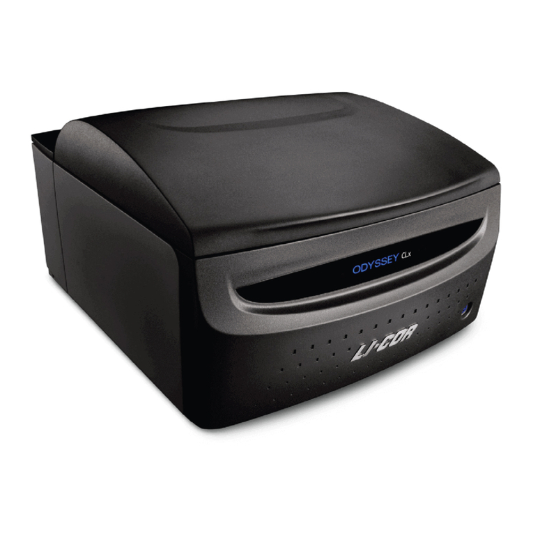
LI-COR
LI-COR Odyssey CLx Operator's manual

Bedcolab
Bedcolab SYMPHONY II Operation and maintenance manual


