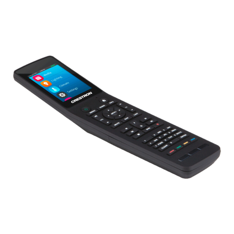
Trianco QAA73 User manual

R
REMOTE
EMOTE CONTROL
CONTROL
QAA73
QAA73
INSTRUCTIONS FOR THE SERVICEMAN
●Installing, using and programming the QAA73 remote control
●Programming boilers Optima CB ed SB with QAA73
●Application examples of a hydraulic installation
●Application examples of a hydraulic installation with additional zones
●Application examples of cascade systems

– 2 –
OPTIMA CB - SB
OPTIMA CB - SB
Service instructions
Service instructions
CONTENTS:
1 General description of the remote control
. . . . . . . . . . . . . . .
pag. 3
2 Preliminary steps for installation and commissioning
. . .
pag. 3
3 Technical characteristics
. . . . . . . . . . . . . . . . . . . . . . . . . . . . . . . . . . . .
pag. 4
4 Installing the appliance
. . . . . . . . . . . . . . . . . . . . . . . . . . . . . . . . . . . . . .
pag. 4
5 Description of the controls
. . . . . . . . . . . . . . . . . . . . . . . . . . . . . . . . . .
pag. 5
6 Displayed information
. . . . . . . . . . . . . . . . . . . . . . . . . . . . . . . . . . . . . . .
pag. 5
7 Operating modes
. . . . . . . . . . . . . . . . . . . . . . . . . . . . . . . . . . . . . . . . . . . . .
pag. 5
7.1 Heating circuits
. . . . . . . . . . . . . . . . . . . . . . . . . . . . . . . . . . . . . . . . . . . . . . .
pag. 5
7.2 Domestic hot water
. . . . . . . . . . . . . . . . . . . . . . . . . . . . . . . . . . . . . . . . .
pag. 5
8 Room temperature adjustmen
. . . . . . . . . . . . . . . . . . . . . . . . . . . . .
pag. 6
9 Comfort/economy mode selector button
. . . . . . . . . . . . . . . .
pag. 7
10 Value reading button
. . . . . . . . . . . . . . . . . . . . . . . . . . . . . . . . . . . . . . . .
pag. 7
11 User programming
. . . . . . . . . . . . . . . . . . . . . . . . . . . . . . . . . . . . . . . . . . .
pag. 8
11.1 List of user parameters
. . . . . . . . . . . . . . . . . . . . . . . . . . . . . . . . . . . . .
pag. 8
11.2 Details of the user parameters
. . . . . . . . . . . . . . . . . . . . . . . . . . . .
pag. 9
12 Installer programming
. . . . . . . . . . . . . . . . . . . . . . . . . . . . . . . . . . . . . .
pag . 11
12.1 List of installer parameters
. . . . . . . . . . . . . . . . . . . . . . . . . . . . . . . . .
pag. 11
12.2 Details of the installer parameter
. . . . . . . . . . . . . . . . . . . . . . . . .
pag. 12
13 Serviceman programming
. . . . . . . . . . . . . . . . . . . . . . . . . . . . . . . . . .
pag. 18
13.1 List of serviceman parameters
. . . . . . . . . . . . . . . . . . . . . . . . . . . . .
pag. 18
13.2 Details of the serviceman parameter
. . . . . . . . . . . . . . . . . . . . .
pag. 19
14 Access to the boiler
. . . . . . . . . . . . . . . . . . . . . . . . . . . . . . . . . . . . . . . . . . .
pag. 25
15
OPTIMA connection wiring diagram . . . . . . . . . . . . . . . . . . .
pag. 26
16
A
CCESS TO THE BOILER
PCB
PARAMETERS USING
THE
QAA 73
REMOTE CONTROL
. . . . . . . . . . . . . . . . . . . . . . . . . .
pag. 27
16.1 Temperatures
. . . . . . . . . . . . . . . . . . . . . . . . . . . . . . . . . . . . . . . . . . . . . . . .
pag. 27
16.2 (Characteristic) heating curves
. . . . . . . . . . . . . . . . . . . . . . . . . . . .
pag. 29
16.3 Installation type configuration
. . . . . . . . . . . . . . . . . . . . . . . . . . . . .
pag. 29
16.4 Timing (or timers)
. . . . . . . . . . . . . . . . . . . . . . . . . . . . . . . . . . . . . . . . . . . .
pag. 29
16.5 Pressures
. . . . . . . . . . . . . . . . . . . . . . . . . . . . . . . . . . . . . . . . . . . . . . . . . . . . . .
pag. 30
16.6 Second circuit - mixed or direct
. . . . . . . . . . . . . . . . . . . . . . . . . . .
pag. 30
16.7 Maximum fan speed during heating
. . . . . . . . . . . . . . . . . . . . .
pag. 30
17 Modifying the serviceman parameters
. . . . . . . . . . . . . . . . . .
pag. 31
17.1 1 Modifying the minimum fan speed (switch from
natural gas to LPG or vice versa)
. . . . . . . . . . . . . . . . . . . . . . . . .
pag. 31
18 Hydraulic diagrams
Application samples
. . . . . . . . . . . . . . . . . . . . . . . . . . . . . . . . . . . . . . . .
pag. 32

– 3 –
OPTIMA CB - SB
OPTIMA CB - SB
Service instructions
Service instructions
The wires used to connect the sensors, remote con-
trols, buses etc.... to the regulator must have double
insulation; alternatively, they must follow a separate
path from that of the mains power supply cables.
Before making the electrical connections,
always ensure that the cables are not live.
Never touch the wires and connections of
the appliance; isolate the appliance from
the electricity mains before making any
connections or disconnections.
QAA73 is a high tech remote control built in complian-
ce with standards , with a weekly timer feature
(with annual date setting), boiler operation and pro-
gramming control functions, zone detector, alarm si-
gnalling and advanced diagnosis.
It guarantees the optimal heat regulation thanks its
microprocessor-based technology. This technical so-
lution allows for the OPTIMA CB and OPTIMA SB
heating units to be controlled according to the chan-
ges in the external temperature.
When programmed correctly and applied to a compa-
tible system, the control unit ensures in real time that
the system heats at the desired temperature and for
the set amount of time.
Warning:
Any other use of this appliance is to be conside-
red improper and consequently dangerous.
For safety reasons, do not open up the regulator
or any of its accessories; all the installation and
maintenance operations and any repair work must
be carried out by authorised professionally quali-
fied servicemen.
The manufacturer will not be liable for any con-
tractual and non-contractual responsibility due to
damages caused by the incorrect installation and
use and, in any case, due to non-compliance with
the instructions provided by the manufacturer.
1 GENERAL DESCRIPTION OF THE REMOTE
CONTROL
2 PRELIMINARY STEPS FOR INSTALLATION
AND COMMISSIONING

– 4 –
OPTIMA CB - SB
OPTIMA CB - SB
Service instructions
Service instructions
47
91
96
96
Auto
04812162024
i
3 TECHNICAL CHARACTERISTICS
Safety class: III (EN 60 730)
Degree of protection: IP20
Operating temperature range: 0÷50°C
Humidity: < 85% relative humidity
connection via “OpenTherm BUS”
Cable: 2 wires
(interchangeable)
Maximum length: 50m
Cable resistance: max 2 x 5 Ohm
Battery life: >12h
fig. 3-1
- Remove the plinth from the front of the appliance as
illustrated in figure 4-2
- Secure the plinth to the wall using screws and the
holes made on the same (fig. 4-3). Warning: the fa-
stening screws are not supplied.
4 INSTALLING THE APPLIANCE
fig. 4-2
- To determine the position of the remote control in
the room, please refer to the figure below
150 cm
min. 20 cm
fig. 4-1
fig. 4-3
12
fig. 4-4
fig. 4-5 fig. 4-6
- Connect the wires to the terminals as indicated in
fig. 4-4 and 4-5
- Replace the front of the appliance as indicated in fig.
4-6.
If the remote control is not installed in a room, but
used momentarily by the serviceman to modify the
parameters, access the electrical parts of the boiler
directly, as illustrated in paragraph 14 herein and con-
nect to the PCB as indicated on page 26.
If on the other hand the remote control is installed in a
room, keep to the instructions below.

– 5 –
OPTIMA CB - SB
OPTIMA CB - SB
Service instructions
Service instructions
5 DESCRIPTION OF THE CONTROLS 7 OPERATING MODES
7.2 DOMESTIC HOT WATER
DOMESTIC HOT WATER TEMPERATURE CONTROL
The temperature value is entered by means of parameter 7;
to access this parameter and modify the value, follow the
instructions provided in paragraph 11 (User parameters).
PROGRAMMING THE DOMESTIC HOT WATER (D.H.W.)
PRODUCTION PERIOD
By modifying the parameters of the remote control QAA73,
you can choose the type of D.H.W. production period pro-
gramming; depending on the parameters set, the produc-
tion may take place continuously (24 hours a day), by fol-
lowing the heating programme one hour ahead or following
the heating programme (again taking into account a certain
advance on the activation of the latter), or even by following
the D.H.W. production programme set on lines 30 ... 36.
The appliance parameters are factory set for the production
of domestic hot water to take place according to the heating
programme one hour ahead (HC - 1 hour).
7.1 HEATING CIRCUITS
Auto
0 4 8 12 16 20 24
i
Prog
1
2
3
4
5
6
7
8
9
Auto
0 4 8 12162024
B
D
A
C
1 - Room temperature control knob
2 - Programme line selector buttons
3 - D.H.W. ON/OFF button
4 - Display
5 - Automatic / permanent / pilot flame operation but-
ton
6 - Parameter value modification buttons
7 - Value reading button
8 - Comfort/economy mode selector button
9 - Flap
To access the internal buttons 2, 3, 5 and 6, pull open
the flap 9 on the control panel.
6 DISPLAY INFORMATION
fig. 5-1
fig. 6-1
A - Current operating mode (horizontal black bars)
B - Normal or modification operation
C - Bars indicating the periods of operation
D - Indication of:
- Burner on
- Comfort mode enabled
- Economy mode enabled
- Anti-frost protection enabled
- Boiler shutdown alarm
To enable the desired function, press button 5 until the hori-
zontal black bar on the display indicating the current opera-
ting mode is positioned underneath the desired function
symbol.
Warning: using the function buttons reserved for central
heating does not affect the production of domestic hot water
in any way, except during programmed holidays and when
the telephone remote control is enabled.
“
AUTOMATIC
”function (Auto ""); enabling it leads to the fol-
lowing conditions:
•Heating circuits 1 and 2 enabled, depending on the timing
programmed on lines 10...16 and 20...26
•Reference temperature according to the heating program-
me
•Anti-frost protection enabled
•Automatic summer/winter commutation enabled
•Holiday programme enabled
“
PERMANENT
”function (dd); enabling it leads to the following
conditions:
•Heating circuits 1 and 2 in continuous operation, irrespecti-
ve of the timing
•room temperature adjustment on the relevant control knob
•protection functions enabled
•automatic summer/winter commutation disabled
•Holiday programme disabled
“
STAND
-
BY
“function (oo); qenabling it leads to the following
conditions:
•central heating turned off
•temperature according to the anti-frost protection
•protection functions enabled
•automatic summer/winter commutation enabled
•holiday programme enabled

– 6 –
OPTIMA CB - SB
OPTIMA CB - SB
Service instructions
Service instructions
The central heating system uses three different configurable re-
ference values:
- reference value for the room temperature described herein
(adjustment via knob ref. 1, figure par. 5)
- reference value for the room temperature in economy mode
(adjustment line 6)
- reference value for the room temperature for the anti-frost
protection (line 5)
EFFECTS OF THE TEMPERATURE ADJUSTMENT
When the reference temperature is enabled, the rooms are
heating according to the adjustment made on the relative con-
trol knob. When you turn the knob, the room temperature re-
quested is displayed as well as set and, if the remote control
QAA73 controls two circuits (HC1 and HC2, for example), the
value will be applied to both circuits.
EFFECTS ON THE DIFFERENT HEATING MODES:
Auto ""The adjustment acts during the set heating periods
dThe adjustment acts continuously
oThe adjustment has not effect whatsoever
Note:
The adjustment made on the control knob has priority over the
reference value for the economy mode of the room temperatu-
re set (line 6), especially if the value set with the knob is lower.
Comfort mode (set with the control knob)
Economy mode (defined on line 5; adjustment range:
between the anti-frost protection value –line 6 –and the
value set with the control knob)
Anti-frost protection (set on line 6; adjustment range:
between 4°C and the economy mode value)
8
ROOM TEMPERATURE ADJUSTMENT
fig. 8-1
MODELS WITH INSTANT HOT WATER PRODUCTION
(OPTIMA CB):
For those models designed to produce hot water instantly,
we recommend you set the hourly D.H.W. production pro-
gramme to “24 hours/day”.
Per eseguire l’impostazione, agire come segue:
- Select line 91 (D.H.W. production mode) by following the
instructions provided in paragraph 12 and set “24
hours/day”.
Activate the D.H.W. production by pressing button 3on the
remote control QAA73 (a horizontal black bar appears be-
neath the symbol s).
MODELS SB (WITHOUT DOMESTIC HOT WATER PRO-
DUCTION DESIGNED TO BE CONNECTED TO A WA-
TER HEATER) WITH A REMOTE WATER HEATER CON-
TROLLED VIA AN NTC SENSOR:
For the D.H.W. programming of these models, proceed as
follows:
- Select line 91 (D.H.W. production mode) by following the
instructions provided in paragraph 12 and choose the de-
sired programme; if you want a programme independen-
tly from the central heating programme, set “prog A.C.S."
("D.H.W. prog.”); at this stage, the programming lines
(from 30 to 36) relative to the D.H.W. production are acti-
vated.
- Activate the D.H.W. production by pressing button 3(a ho-
rizontal black bar appears beneath the symbol s).
FOR MODELS SB (WITHOUT D.H.W. PRODUCTION DE-
SIGNED TO BE CONNECTED TO A WATER HEATER)
WITH A REMOTE WATER HEATER CONTROLLED VIA
A THERMOSTAT:
The D.H.W. temperature is adjusted on the indirect cylinder
thermostat.
The production of domestic hot water starts on closing of
the thermostat contacts.
The remote control QAA73 has no control over the indirect
cylinder; button 3is disabled.

– 7 –
OPTIMA CB - SB
OPTIMA CB - SB
Service instructions
Service instructions
Press this button repeatedly to display the
following information in sequence:
1 - Correct time, room temperature measured and opera-
ting mode
2 - Error indication
3 - Service display
4 - Correct time and operation of the heating circuit 1
5 - Correct time and date
6 - Current value of the external temperature
7 - Minimum value of the external temperature *
8 - Maximum value of the external temperature *
9 - Current value of the room temperature
10 - Minimum value of the room temperature *
11 - Maximum value of the room temperature *
12 - Current value of the domestic hot water temperature
13 - Current value of the boiler temperature
14 - Current value of the flow temperature
15 - Burner modulation
16 - Central heating circuit pressure
Based on the parameter set on line 150, the display
can be continuous or it can return to the normal rea-
ding after 8 minutes of inactivity.
* - Absolute minimum and maximum temperature recorded
on activation of the remote control QAA73; to reset the
recording, press buttons +/- at the same time for 3 se-
conds.
10
VALUE READING BUTTON
i
fig. 10-1
During the "automatic“(Auto")) and ”perma-
nent“(dd)heating circuit operating modes, this
button allows you to switch automatically from
the comfort mode to the economy mode.
Effect on the “AUTOMATIC”mode (Auto"):
The operating mode switches simultaneously from comfort
to economy mode or vice versa; the effect will be reflected
on the heating circuits 1 and 2, or only on circuit 1, depen-
ding on the setting made by the serviceman on line 153
Effect on the “PERMANENT”mode (dd):
The operating mode switches simultaneously from comfort
to economy mode and vice versa.
This switch does not affect the D.H.W. production or the ho-
liday programme.
In the event of the automatic summer/winter variation, the
switch is disabled.
9
COMFORT/ECONOMY MODE SELECTOR
BUTTON
i
fig. 9-1

– 8 –
OPTIMA CB - SB
OPTIMA CB - SB
Service instructions
Service instructions
Push-button
Indication Line
11
2
from 1 to 50
11
USER PROGRAMMING
Below is the generalised sequence of use of the buttons to modify
the parameters reserved for the user.
i
Prog
i
Prog
Press one of the line selec-
tor buttons to access the
programming operations.
Press one of these selec-
tor buttons to access the
desired line
Push-button
Indication Line
3
4Continuous
Display
i
i
Press the adjustment but-
tons to set the desired va-
lue; the value is stored
when you quit the pro-
gramming or when you
change line
Press the VALUE REA-
DING button to quit the
programming.
Factory Setting Range of
Line Function
setting made value
CLOCK:
01 Time setting - …
00:00÷23:59
02 Date (day, month) -
…
01.01÷31.12
03 Year -
…
1999÷2099
SETTING THE OPERATING TEMPERATURES
05 Temperature value for the economy mode (TRRw) 16,0 …
TRF…TRN
06 Anti-frost protection value of the room temperature (TRF) 10,0 …4…TRRw
07 Nominal value of the domestic hot water temperature (TBWw) 55,0 …
TBWR…TBWmax
PROGRAMMING THE HEATING CIRCUIT 1 TIMES
10 Selection of the programming period --.-- …
Mo…Sun, week
11 Start of the first heating period 06:00 …
--:--…24:00
12 End of the first heating period 22:00 …
--:--…24:00
13 Start of the second heating period --.-- …
--:--…24:00
14 End of the second heating period --.-- …
--:--…24:00
15 Start of the third heating period --.-- …
--:--…24:00
16 End of the third heating period --.-- …
--:--…24:00
PROGRAMMING THE HEATING CIRCUIT 2 TIMES
20 Selection of the programming period --.-- …
Mo…Sun, week
21 Start of the first heating period 06:00 …
--:--…24:00
22 End of the first heating period 22:00 …
--:--…24:00
23 Start of the second heating period --.-- …
--:--…24:00
24 End of the second heating period --.-- …
--:--…24:00
25 Start of the third heating period --.-- …
--:--…24:00
26 End of the third heating period --.-- …
--:--…24:00
PROGRAMMING THE D.H.W. TIMES:
30* Selection of the programming period --.-- …
Mo…Sun, week
31* Start of the first D.H.W. period 06:00 …
--:--…24:00
32* End of the first D.H.W. period 22:00 …
--:--…24:00
33* Start of the second D.H.W. period -- …
--:--…24:00
34* End of the second D.H.W. period -- …
--:--…24:00
35* Start of the third D.H.W. period -- …
--:--…24:00
36* End of the third D.H.W. period -- …
--:--…24:00
HOLIDAY PROGRAMMING:
40 Start of the holiday period (day, month) --.-- …
1 jan…31 dec
41 End of the holiday period (day, month) --.-- …
1 jan…31 dec
42 Type of operation of the heating circuit during …Anti-frost
the holiday period Anti-frost or reduced
GENERAL:
45 Resetting the settings made on lines 10...16, 20...26 and 30...36 No - Yes/No
(Keep the + and - buttons pressed together for more than 3 seconds)
46 Winter/summer commutation temperature value 17,0 …8…30
47 language Italian -
50 Error display -- - 0…255
11.1
LIST OF USER PARAMETERS
* - Only enabled when parameter 91 (installer parameters, see the next paragraph) is set to “Prog d.h.w”.

– 9 –
OPTIMA CB - SB
OPTIMA CB - SB
Service instructions
Service instructions
LINE 15: the adjustment buttons (+) or (-) allow you to
set the starting time of the third heating period
of the day or period selected in line 10: by kee-
ping the buttons pressed, the minutes change
quickly.
LINE 16: the adjustment buttons (+) or (-) allow you to
set the stopping time of the third heating period
of the day or period selected in line 10: by kee-
ping the buttons pressed, the minutes change
quickly.
Warning:
- If the starting and stopping times of the heating are
different for each day of the week, the parameters
will have to be set for each day; if the two times coin-
cide, select the block “1-7”in line 10 and set the ti-
mes.
- For the selection of the heating period, the time in-
creases in 10-minute intervals until 00.00 or 24.00 of
the day set in line 10. If you have to set the time for
the next day, first set the number of the day in line
10.
- The time set for the heating period to stop may not be
before, or coincide with the starting time of this same
period.
- When you first programme them, “--.--”appears in li-
nes 11…16. To enter the time, press the “–”button
once: you will see “24.00”on the display; now you
can enter the desired time.
PROGRAMMING THE HEATING TIMES OF CIRCUIT 2
(LINES 20 - 26):
The programming of the heating periods for circuit 2 follow
the same procedure used for circuit 1; therefore, to set it
you can follow the instructions from line 10 to line 16.
PROGRAMMING THE DOMESTIC HOT WATER HEA-
TING TIMES (LINES 30 - 36 ):
To programme the domestic hot water production, you must
do the same as for the heating circuits; therefore, to set it
you can follow the instructions from line 10 to line 16.
The programming can be carried out only if “Prog. dhw”has
been set in line 91.
PROGRAMMING THE HOLIDAY PERIOD:
The programming of lines 40...42 can only be carried out in
automatic mode (Auto").
Line 41 can be programmed only if an initial date has been
set in line 40.
During the period set in lines 40 and 41, the boiler operates
according to the value set in economy mode or according to
the anti-frost protection value, depending on how line 42
was programmed.
During the holiday programme, the domestic hot water pro-
duction is blocked.
LINE 1: the adjustment buttons (+) or (-) allow you to
set the correct time: by keeping the buttons
pressed, the minutes change quickly.
LINE 2: the adjustment buttons (+) or (-) allow you to
set the correct date: by keeping the buttons
pressed, the days change quickly.
LINE 3: the adjustment buttons (+) or (-) allow you to
set the correct year: by keeping the buttons
pressed, the numbers change quickly.
TEMPERATURE
LINE 5: the adjustment buttons (+) or (-) allow you to
set the ECONOMY SET POINT (ECONOMY
MODE REFERENCE VALUE) referring to the
value of the room temperature. If this tempera-
ture drops below the reference value, the boiler
will start and will continue to operate until the
room temperature reaches the value set.
LINE 6: the adjustment buttons (+) or (-) allow you to
set the ANTI-FROST PROTECTION SET
POINT (ANTI-FROST PROTECTION REFE-
RENCE VALUE) referring to the value of the
room temperature. If this temperature drops
below the reference value, the boiler will start
and will continue to operate until the room tem-
perature reaches the value set.
LINE 7: the adjustment buttons (+) or (-) allow you to
set the SET POINT (REFERENCE VALUE) of
the domestic hot water temperature value.
PROGRAMMING THE HEATING CIRCUIT 1 TIMES:
LINE 10: the adjustment buttons (+) or (-) allow you to
select the day (or the block 1-7) to be program-
med
LINE 11: the adjustment buttons (+) or (-) allow you to
set the starting time of the first heating period
of the day or period selected in line 10: by kee-
ping the buttons pressed, the minutes change
quickly.
LINE 12: the adjustment buttons (+) or (-) allow you to
set the stopping time of the first heating period
of the day or period selected in line 10: by kee-
ping the buttons pressed, the minutes change
quickly.
LINE 13: the adjustment buttons (+) or (-) allow you to
set the starting time of the second heating pe-
riod of the day or period selected in line 10: by
keeping the buttons pressed, the minutes
change quickly.
LINE 14: the adjustment buttons (+) or (-) allow you to
set the stopping time of the second heating pe-
riod of the day or period selected in line 10: by
keeping the buttons pressed, the minutes
change quickly.
11.2
DETAILS OF USER PARAMETERS

– 10 –
OPTIMA CB - SB
OPTIMA CB - SB
Service instructions
Service instructions
LINE 47: the adjustment buttons (+) or (-) allow you to
select the language of the display on the
screen.
LINE 50: error code indication reading.
The appliance is designed to identify and di-
splay errors which occur inside it or in the cir-
cuit. In the event of internal errors or circuit
malfunction, the symbol comes up on the di-
splay.
Once line 50 has been selected, “error”comes
up on the display, followed by the relevant co-
de and a brief description of the error itself.
The codes and their meanings are indicated in
the instruction manual for the boiler installer.
Once the set holiday period is over, the normal weekly pro-
gramming will be restored.
The dates indicating the beginning and the end of the holi-
day are automatically reset when the holiday is over.
To reset or interrupt the programme in advance, select line
40 or 41 and keep buttons + and - pressed for 3 seconds.
LINE 40: the adjustment buttons (+) or (-) allow you to
select the day on which the holiday period is to
be activated. By keeping the buttons pressed,
the days change quickly.
LINE 41: the adjustment buttons (+) or (-) allow you to
select the day on which the holiday period is to
be deactivated. By keeping the buttons pres-
sed, the days change quickly..
LINE 42: the adjustment buttons (+) or (-) allow you to
select the boiler's operating mode during the
holiday programme (economy mode or anti-fro-
st protection).
GENERAL
LINE 45: restoring the default settings in lines 10...16,
20...26 and 30...36 (keep the buttons + and -
pressed for at least 3 seconds).
LINE 46: the adjustment buttons (+) or (-) allow you to
set the temperature commutation between
SUMMER / WINTER, calculated according to
the average value of the external temperature
over a set period of time and to the type of buil-
ding (installer parameters) for heating circuit 1
(ref. Diagram in figure 11.2-1). As soon as this
value exceeds the set temperature by 1 de-
gree, the boiler automatically activates the do-
mestic hot water production, while, if the same
value drops 1 degree below the set value, the
boiler will activate both the heating function
and the domestic hot water production (please
note that, if there is a sudden temperature
drop, the heating is not activated).
The increase in this value results in the change
being brought forward in WINTER and delayed
in SUMMER; whereas, the decrease in this va-
lue results in a delayed activation in WINTER
and an early activation in SUMMER.
The function only has effect if it is carried out in
automatic mode (Auto").
ON
17
T (°C)
THG
TAged
OFF
t (min)
THG +1 °C
THG –1 °C
16
18
19
20
Taged = average value of the external temperature calcula-
ted
THG = winter/summer commutation temperature value
Central heating turned off (switch from winter to summer po-
sition) when: TAged > THG +1°C
Central heating turned on (switch from summer to winter po-
sition) when: TAged < THG -1°C
fig. 11.2-1
Central heating

– 11 –
OPTIMA CB - SB
OPTIMA CB - SB
Service instructions
Service instructions
Factory Setting Range of
Line Function
setting made values
SERVICE VALUES
51
Reading of the room temp. in the current mode of heating circuit 1.
--0…35,0
°C
Comfort, economy mode or anti-frost protection value
52
Reading of the room temp. in the current mode of heating circuit 2.
--0…35,0
°C
Comfort, economy mode or anti-frost protection value
53
Reading of corrected external temperature.
- - -50…+50 °C
Adjustable to the current value by pressing the + and - buttons for at least 3 seconds
54
Reading of mixed external temperature
- -50…+50 °C
55 Not available - - -
56 Not available - - -
57
Reading of the current value of the D.H.W. return temperature
- -40…+127°C
58 Not available - - -
59 Not available - - -
61 Not available - - -
62 Open therm mode Plus - Plus
63 Reading of flow set value for heating circuit HC1 - - 0…100 °C
64 Reading of flow set value for heating circuit HC2 - - 0…100 °C
HEATING CIRCUITS HC1 AND HC2
70 Slope of heating curve HC1 (- - = not active) 15,0 …2,5…40,0
71 Min. limit of boiler flow temperature (TVmin) 8 …8…TVmax
72 Max. limit of boiler flow temperature (TVmax) 80 …
TVmin…TKmax
TKmax= max. boiler temperature
73 Parallel shift of the heating curve for circuit 1 0,0 …-4,5…+4,5
74 Type of building Light …
light/heavy
75 Influence of room
(None, on HC1, on HC2, on HC1 + HC2)
su HC1 …
76 Room temperature commutation differential ––.–0,5…4,0
––.–= inactive
77 Adjustment of the heating curve Active …
active/inactive
78 Max. advanced starting time to optimise the control of the ignition 100 min …0…360 min
79 Max. advanced starting time to optimise the control of the stopping 30 min …0…360 min
80 Slope of heating curve HC2 (––.–= inactive) 15,0 …2,5…40,0
81 Min. limit of the flow temperature for heating circuit 2 (TV2min) 8 …8…TV2max
82 Max. limit of the flow temperature for heating circuit 2 (TV2max) 80 …
TV2min…TKmax
83 Parallel shift of the heating curve for circuit 2 0,0 …-4,5…+4,5
DOMESTIC HOT WATER
90 Adjustment of the reduced temperature of D.H.W.
40 …8…TBWw
91 Domestic hot water production mode
HC -1h
…
24hours/day, Prog HC -1h, Prog HC, Prog d.h.w.
92 Legionnaire's disease function (OFF, weekly, daily) Weekly
…
93
Activation (with ECO)/deactivation (without ECO) comfort mode in D.H.W without ECO
…
with / without ECO
GENERAL
95 Operation blockage OFF
…
OFF / ON
96 Reference clock (master) QAA73 QAA73
QAA73/External
97 Date of time change, from summer time to standard time (+1h)
25 mar 25 mar 01jan…31dec
98 Date of time change, from summer time to standard time
25 oct 25 oct 01jan…31dec
12.1
LIST OF INSTALLER PARAMETERS
12
INSTALLER PROGRAMMING
Below is the generalised sequence of use of the buttons to mo-
dify the parameters reserved for the installer.
Push-button
Indication Line
3
from 51 to 98
4
5Continuous
diaplay
i
Prog
Press one of these selec-
tor buttons to access the
desired line
i
i
Press the adjustment buttons
to set the desired value; the va-
lue is stored when you quit the
programming or when you
change line.
Press the VALUE REA-
DING button to quit the
programming.
Push-button
Indication Line
11
251
i
Prog
i
Prog
Press one of the line selector
buttons to access the pro-
gramming operations.
Keep both buttons indicated
opposite pressed simulta-
neously until you select pro-
gramming line 51, and then
release them

– 12 –
OPTIMA CB - SB
OPTIMA CB - SB
Service instructions
Service instructions
LINE 51:
Reading of the value set for the current hea-
ting mode which is active in circuit 1
(comfort, economy or anti-frost protection).
LINE 52:
Reading of the value set for the current hea-
ting mode which is active in circuit 2
(comfort, economy or anti-frost protection).
LINE 53:
The corrected external temperature is the room
temperature simulated in a fictitious building
without a source of internal heat. This means
that the external temperature alone affects the
room temperature.
The corrected external temperature is genera-
ted by the regulator. It is constantly calculated
according to the actual external temperature.
The corrected external temperature only has
direct influence on the summer/winter commu-
tation.
The corrected external temperature has an in-
direct effect, via the mixed external temperatu-
re, on the control of the flow temperature..
No direct adjustment can be made. The gene-
ration of the corrected external temperature
cannot be affected.
Nonetheless, the corrected external temperatu-
re can be reset.
For example:
12.2
DETAILS OF INSTALLER PARAMETERS
LINE 54: The mixed external temperature is the
combination of the actual external tempe-
rature and the corrected external tempera-
ture calculated by the regulator.
The mixing of the actual and corrected ex-
ternal temperature depends on the con-
struction characteristics of the building (li-
ne 74) and takes place as follows:
TYPE OF MIXED EXTERNAL
BUILDING TEMPERATURE
Heavy TAgem = 1/2 TAakt + 1/2 TAged
Light TAgem = 3/4 TAakt + 1/4 TAged
The mixed external temperature acts as a
reference value (compensation variable)
for the adjustment of the flow temperature,
in order to adapt it to the current atmo-
spheric conditions.
It also acts on the “automatic limitation of
daily heating" to stop heating.
For example:
LINE 62: OpenTherm “Plus”is the protocol used for
the communication between the boiler
adjustment (PCB) and the remote control
(Ecotronic); it also allows for the reading
and modification of a number of functions
via the bus.
18:00
13
14
15
16
17
TA
°CTAakt
TAged
06:00 18:00 06:00 18:00 t
TAakt - current external temperature
TAged - corrected external temperature
18:00
13
14
15
16
17
TA
°CTAakt
TAged
TAgem1
TAgem0
06:00 18:00 06:00 18:00 t
TAakt - external temperature measured
TAged - corrected external temperature
TAgem1 - mixed external temperature for light con-
struction building
Tagem0 - mixed external temperature for heavy con-
struction building
fig. 12.2-1
fig. 12.2-2

– 13 –
OPTIMA CB - SB
OPTIMA CB - SB
Service instructions
Service instructions
LINE 70: the adjustment buttons (+) or (-) allow you
to set the slope of the heating curve for the
heating circuit; the correct adjustment of
the latter allows you to establish a constant
room temperature despite any variations in
the external temperature. The curve must
be set according to the type of system and
the type of building. Consequently, before
you modify its value and to ensure the opti-
mum operation of the installation, ask an
authorised service centre for advice.
The regulator generates the flow reference
temperature according to the selected hea-
ting curve.
––. –
All the heating circuit functions
are deactivated; the anti-frost
protection is active only for the
heating module and the indirect
cylinder.
2.5...40.0
All the heating circuit functions
are activated
LINE 71: the adjustment buttons (+) or (-) allow you
to set the minimum limit of the boiler flow
temperature.
LINE 72: the adjustment buttons (+) or (-) allow you
to set the maximum limit of the boiler flow
temperature.
LINE 73: Produces a parallel shift of the heating
curve for circuit 1.
The modification of the values entered will
increase or decrease the reference tem-
perature. This is a basic setting which,
although having the same effect as an
adjustment carried out using the knob, ac-
20 10 0 -10 -20 -30
90
80
70
60
50
40
30
°C
°C
40 35 30 27,5 25 22,5
20
17,5
15
12,5
10
7,5
5
2,5
100
tually influences the position of the set-
tings on the knob.
Note:
The adjustment made on the knob will be
out of phase compared to the resetting,
which makes it possible to calibrate the
settings.
Parallel shift
Any further reference temperature adjust-
ment, whether it be by means of the set
value or the type of operation, results in a
parallel shift of the heating curve.
LINE 74:
the adjustment buttons (+) or (-) allow you
to set the type of building.
It is a function which takes into account the
thermal inertia of the building.
The setting will modify the generation of
the mixed external temperature, which will
allow the system controlled to be adapted
to the type of building.
Heavy construction: (building with thick or
well insulated walls):
The room temperature will respond more
slowly to the variations of the external tem-
perature.
Light construction (building with thin walls):
The room temperature will respond more
rapidly to the variations of the external tem-
perature.
20 10 0 -10 -20 -30
90
80
70
60
50
40
30
°C
°C
100
0
10 10
0
30
TR w
TA
TV
TV Flow temperature
TA Mixed external temperature
TRw Reference room temperature
(also known as room reference temperature)
fig. 12.2-4
Flow temperature
External temperature calculated
slope of the curve
fig. 12.2-3

– 14 –
OPTIMA CB - SB
OPTIMA CB - SB
Service instructions
Service instructions
LINE 75: Influence of the room temperature, i.e. the
shifts in values between the actual room
temperature and the reference room tem-
perature are measured and taken into ac-
count in the adjustment of the temperatu-
re. Hence the return signal of the room
temperature allows you to obtain a more
precise adjustment of the temperature.
The setting will activate or deactivate the
effect of the room temperature shifts on
the temperature adjustment.
To use this function, the following condi-
tions must apply:
The external sensor must be connected to
the boiler
The “Influence of the room temperature"
(75) setting must be active (it must not be
set to “None”).
No regulated thermostatic valve must be
installed inside the room with the boiler (if
there is one, it must be in the "completely
open" position).
NONE Influence of the room temperature inacti-
ve; the room temperature measured has
no effect on the temperature adjustment.
ONHC1 Influence of the room temperature active
on the circuit HC1: the room temperature
measured affects the adjustment of the
temperature of the heating circuit 1.
ONHC2 Influence of the room temperature active
on the circuit HC2: the room temperature
measured affects the adjustment of the
temperature of the heating circuit 2.
ONHC1 Influence of the room temperature active
+HC2 on the circuits HC1 and HC2: the room
temperature measured affects the adjust-
ment of the temperature of both the hea-
ting circuits.
LINE 76: controls the room temperature by means
of heating circuits with circulation pumps.
Prevents the room temperature from be-
coming too high in heating circuits with cir-
culation pumps.
Effect:
The commutation differential for the on-off
control will be modified.
-.- = the differential is inactive;
the circulation pump
always remains active
Decrease = The commutation diffe-
rential takes on a lower
value; the circulation pum-
ps are activated and
deactivated more frequen-
tly.
The room temperature va-
ries within a narrower in-
terval
Increase = The commutation diffe-
rential takes on a higher
value; the circulation pum-
ps must be activated and
deactivated less frequen-
tly.
The room temperature va-
ries within a narrower in-
terval
Room temperature adjustment
In heating circuits with circulation pumps,
heat production is controlled by the activa-
tion and deactivation of circulation pumps.
This is carried out using an on-off control
of the room temperature differential.
OFF
ON
°C
°C
TRx
TRw+SDR
TRw
t
ON
w
OFF
Circulation
pump
Circulation
pump
76
fig. 12.2-5
Legend:
TRx = Current room temperature value
TRw = Room temperature setpoint
SDR = Room temperature commutation differential
°C = Temperature
t = Time
w = Setpoint

– 15 –
OPTIMA CB - SB
OPTIMA CB - SB
Service instructions
Service instructions
LINE 77: The self-adjustment function takes into ac-
count the different heating situations and
adapts the adjustment to the heating cir-
cuit regularly.
The self-adjustment function automatically
matches the heating characteristic to the
type of building and heat requirements.
The self-adjustment takes into account the
shifts in room temperature, the variation of
the external temperature and the sensiti-
vity to adjustment.
Adjustment inactive: the heating curve will
use the set parameters
Adjustment active: the heating curve will
be adjusted automatically and continuou-
sly according to the parameters set in line
75.
Note:
For an optimal self-adjustment, it would be
best if the circumstances listed below oc-
curred as rarely as possible, in particular
just after commissioning, otherwise the
adjustment calculation is partially incor-
rect:
- Manual correction of the heating curve
- Power supply cut off
- Heating characteristic set to -- --
- Modification of the reference room
temperature
An analysis of the room temperature adju-
stment for the previous day is carried out
at midnight. This analysis leads to an au-
tomatic correction of the heating curve.
SIMPLE SELF-ADJUSTMENT (RANGE 3):
For average external temperatures below
4 °C, only the slope of the heating curve is
adjusted. The correction of the slope is
balanced, within this range of temperatu-
res, by the factor f2 and the sensitivity to
adjustment 2.
COMBINED SELF-ADJUSTMENT (RANGE 2):
For average external temperatures
between 4 and 12 °C, the slope is partially
adjusted, and so is the parallel shift the
curve. The correction of the shift is balan-
ced, within this range of temperatures, by
the factor f1 and the sensitivity to adjust-
ment 1.
The correction of the slope is balanced,
within this range of temperatures, by the
factor f2 and the sensitivity to adjustment 2.
NO SELF-ADJUSTMENT (RANGE 1):
For average external temperatures in ex-
cess of 12 °C, the heating curve is not
adjusted.
For example, for a reference room tempe-
rature in comfort mode of 20 °C:
LINE 78: This is a function that precedes the star-
ting of the system according to the pro-
grammed time, to obtain the required
comfort level once the automatic commu-
tation time has been reached.
The function is only effective when line 75
is active (it is not in the “None”position).
In underfloor heating systems (with the
heat coming from the floor), the time in ad-
vance must be greater compared to that of
systems which use heat emitters (radia-
tors).
LINE 79: This is a function that precedes the turning
off of the system according to the pro-
grammed time, to obtain the required re-
duction level once the automatic commu-
tation time has been reached.
The function is only effective when line 75
is active (it is not in the “None”position).
0
TA
12 4 -4 -12
0,5
1
f
20
ged
f
1
f
2
ZAF1 ZAF2
f Factor
f1 Factor for the parallel shift
f2 Factor for the slope
TAged Corrected external temperature
ZAF1 Sensitivity to adjustment 1
ZAF2 Sensitivity to adjustment 2
fig. 12.2-6

– 16 –
OPTIMA CB - SB
OPTIMA CB - SB
Service instructions
Service instructions
LINE 80: As for line 70, but for heating circuit 2
LINE 81: As for line 71, but for heating circuit 2
LINE 82: As for line 72, but for heating circuit 2
LINE 83: As for line 73, but for heating circuit 2
LINE 90: Defines the minimum temperature limit va-
lue at which the D.H.W. (D.H.W. economy
reference temperature) will be maintained
during the D.H.W. programme periods (li-
nes 19 ...25) which are not for the produc-
tion of domestic hot water.
Note:
If the domestic hot water production is
controlled by a thermostat, the D.H.W.
economy reference temperature will not
be applicable.
LINE 91: This is where the timing system for the
production of D.H.W. is chosen; according
to the set parameters, the production can
be continuous (24 hours a day), in accor-
dance with the heating programme (taking
into account the advance time period com-
pared to the activation thereof) or in accor-
dance with the D.H.W. production pro-
gramme set in lines 30 ... 36.
The D.H.W. function may be activated or
deactivated by pressing the corresponding
button (s).
The D.H.W. anti-frost temperature is set at
5 °C and it is always active.
Some examples of the effect of set para-
meters
24H/DAY
ACCORDING TO THE HEATING PROGRAM-
ME, WITH 1 HOUR IN ADVANCE
ACCORDING TO THE HEATING PROGRAMME
ACCORDING TO THE DOMESTIC HOT WATER
PRODUCTION PROGRAMME (LINES 30 …36)
LINE 92: The anti-Legionnaire’s disease function
ensures that the domestic hot water
(D.H.W.) contained in the storage indirect
cylinder is brought to a temperature of at
least 60°C regularly, to prevent the prolife-
ration of bacteria that cause Legionnaire’s
disease.
The function will be activated every
Monday morning with the first D.H.W. hea-
ting and it will remain active for a period of
at least two and a half hours.
Note:
This function is only available if the
D.H.W. production is authorised by the
D.H.W. production programme.
If the anti-Legionnaire’s disease function
is hindered during the period it is normally
scheduled for (Mondays), it will be repea-
ted the next time the D.H.W. is heated.
Legionnaire’s disease
In certain conditions in stagnant water,
bacteria may form and build up, causing
serious infections such as Legionnaire’s
disease, for example. To minimise this ri-
sk, the temperature of the water must be
raised regularly to a set number of de-
grees.
The risk of Legionnaire’s disease sprea-
ding mostly arises in central heating sy-
stems with a widespread network of pipes,
as well as in air conditioning systems.
To minimise the risk of infection, these sy-
stems must be installed and serviced cor-
rectly.
In large systems, the water outlet tempe-
rature must be at least 60 °C and the tem-
perature of the water in the piping network
must not drop below 5 °C.
0 6 11 17 2422 h
C
0 6 12 18 24 h
065111716 2422 h
C
0 6 12 18 24 h
C
fig. 12.2-7
fig. 12.2-8
fig. 12.2-9
fig. 12.2-10

– 17 –
OPTIMA CB - SB
OPTIMA CB - SB
Service instructions
Service instructions
LINE 93: This parameter is used in the CB models
for which you wish to use the D.H.W.
comfort function.
Press button 3 repeatedly to display the
following information in sequence:
D.H.W. production
active, D.H.W.
comfort active in
this case, after
drawing water, the
boiler maintains the
D.H.W. temperature at the value set with
parameter 607 (D.H.W. comfort reference
temperature) for the adjustment of the boi-
ler (see par. 16) for the amount of time set
with parameters 602 and 603.
D.H.W. production
active, D.H.W.
comfort inactive: in
this case, after
drawing D.H.W.,
the boiler does not
perform a comfort
cycle.
D.H.W. production
deactivated.
LINE 95: When the parameters set are considered
to be final, it is possible to use this func-
tion to block the appliance and avoid any
tampering.
Off: all functions are accessible and can
be modified
On: all functions are displayed but cannot
be modified (if you try to modify them, the
symbol appears)
TEMPORARY DEACTIVATION OF THE
BLOCKING FUNCTION
The function may be temporarily deactiva-
ted to allow the parameters to be pro-
grammed or set (or adjusted).
To do this, keep the buttons❷!and ❿
pressed simultaneously for at least 3 se-
conds. This temporary deactivation of the
function lasts until you leave the program-
ming mode (by pressing button ).
PERMANENT DEACTIVATION OF THE
BLOCKING FUNCTION
Press the buttons ❷!and ❿simultaneou-
sly for at least 3 seconds and set parame-
ter 95 to OFF.
LINE 96: Determines the appliance to which the sy-
stem refers in terms of the correct time.
QAA73 = remote control QAA 73
Esterno= another appliance
LINE 97 This function allows you to change the ti-
me on the clock automatically, from stan-
dard time to summer time.
The clock goes on to summer time the
Sunday after the set date.
LINE 98 This function allows you to change the ti-
me on the clock automatically, from sum-
mer time to standard time.
The clock goes on to standard time the
Sunday after the set date.
i
3
3
3

– 18 –
OPTIMA CB - SB
OPTIMA CB - SB
Service instructions
Service instructions
Push-button
Indication Line
11
2
3CODE
Press the sequence of but-
tons
5 stars will be displayed; if the
code is correct, direct access
will be provided to the servi-
ceman parameters; however,
if it is incorrect, the display will
indicate the installer parame-
ter settings.
Below is the generalised sequence of use of the buttons to
modify the parameters reserved for the serviceman.
i
Prog
i
Prog
i
Prog
Press one of the line selec-
tor buttons to access the
programming operations.
Keep the selector buttons
pressed together for more
than 9 seconds until the indi-
cation “code OEM _ _ _ _
_”appears, then release
them
i
i
Push-button
Indication Line
4from 100 to
199
5
6
6Continuous
display
i
Prog
Press one of these selec-
tor buttons to access the
desired line
i
i
Press the adjustment but-
tons to set the desired va-
lue; the value is stored
when you quit the pro-
gramming or when you
change line
Press the VALUE REA-
DING button to quit the
programming.
Factory Setting Range of
Line Function
setting made values
HEATING
100
Maximum room temperature reference value (TRwMax)
35°C
…
TRwMin…35
101
Minimum room temperature reference value (TRwMin)
10°C
…
4…
TRwMax
102
Influence factor of the room temperature (KORR) 4
…
0…20
103 Accelerated drop constant (KON; without room sensor) 2
…
0 ÷20
104 Accelerated heating - excess heating beyond the reference 5°C
…
0 ÷20
room temperature value (DTRSA)
105 Flow reference temperature increase limit 5
…
0…15
106 Correction of the room temperatures measured 0
…
-3,0…3,0
DOMESTIC HOT WATER
130 Maximum D.H.W. reference value (TBWmax) 60
…
TBWw…80
TBWw = reference value of the flow temperature in D.H.W. comfort mode.
131 Anti-Legionnaire’s disease function reference value 65
…
8…95
SERVICE FUNCTIONS
150 Information display
temporary
…
tempor./perm.
151 Frost warning (-.- = disabled) 3,0°C
…
-10…+10
152 Control (or reference value) knob free
…blocked/free
153 Effect of the COMFORT/ECONOMY mode commutation button
onHC1+HC2
…
on HC1+HC2
or on HC1
199 Remote control QAA73 software version - - 0…99.9
13.1
LIST OF SERVICEMAN PARAMETERS
13
SERVICEMAN PROGRAMMING

– 19 –
OPTIMA CB - SB
OPTIMA CB - SB
Service instructions
Service instructions
LINE 100: Limits the maximum room temperature re-
ference value (or reference room tempera-
ture).
LINE 101: Limits the minimum room temperature re-
ference value (or reference room tempera-
ture).
LINE 102: Defines the influence of the shift in the re-
ference room temperature on the system.
The influence of the room temperature
can be enabled and disabled (parameter
setting on line75)
This parameter setting will modify the in-
fluence of the room temperature.
Increase: the influence of the temperature
will increase
Decrease: the influence of the room tem-
perature will decrease.
Correction:
The following example shows how and ac-
cording to which formula the reference
room temperature is corrected.
TRwk = Reference room temperature
TRw (Reference room temperature) = 20°C
TRx (Room temperature measured) = 22°C
Correction factor KORR = 10
TRwk= TRw + KORR x (TRw - TRx)
2
TRwk= 20°C+10 x (20°C - 22°C) = 10°C
2
LINE 103:
The accelerated drop constant takes advantage
of the heat accumulation capacity of a building
and modifies the duration of the rapid temperatu-
re rise.
The drop constant is only enabled in adjustments
with no influence of the room temperature.
Increase: the drop duration is extended (for well
insulated buildings, which cool down slowly)
Decrease: the drop duration is reduced (for
poorly insulated buildings, which cool down ra-
pidly)
ACCELERATED DROP WITH NO INFLUENCE
OF THE ROOM TEMPERATURE
The accelerated drop starts as soon as there is a
commutation on a lower reference room tempera-
ture (for commutation in automatic mode, for
example).
The circulation pump of the heating circuit is disa-
bled until the end of the accelerated drop dura-
tion, the parameters of which are set on line 103,
of the mixed external temperature and the shift in
the reference room temperature.
The duration of the accelerated drop is limited to
a maximum of 15 hours.
Example of a shift in reference temperature of
4°C (from 20 to 16°C, for example):
Setting on line 103
TAgem 0 4 8 12 15 20
-20000000
- 10 0 0.5h 1h 1.5h 2h 2.5h
0 0 3h 6h 9h 11h 15h
+10 0 5h 11h 15h 15h 15h
LINE 104: This function cuts the amount of time for
the rise in temperature of the part.
The function acts on the heating circuit se-
lected on line 75.
Increase: the duration of the temperature
rise is shorter
Decrease: the duration of the temperature
rise is longer
Accelerated temperature rise
The accelerated temperature rise starts as
soon as there is a commutation on a hi-
gher reference room temperature (hours
of commutation in automatic mode, for
example).
By setting the parameter on line 104, the
reference room temperature is raised until
13.2
DETAILS OF SERVICEMAN PARAMETERS
30
252015
10
5
30
25
20
15
10
5
TRwk [°C]
KORR=4
TRx
KORR=10 °C
TRw
fig. 13.2-1
Correction of the defined value of the room temperature

– 20 –
OPTIMA CB - SB
OPTIMA CB - SB
Service instructions
Service instructions
the room is at the right temperature (TRw-
1/4 °C).
The accelerated temperature rise causes
a rise in the flow reference temperature.
TRx - Room temperature measured
TRw - Reference room temperature
104 - Excess heating beyond the reference
room temperature value
t - Time
LINE 105: This function limits the increase in the flow
reference temperature (K/min).
The limit set applies in this case to both
central heating circuits.
LINE 106: The function allows for the calibration of
the room temperature sensor, in order to
obtain a more precise display of the tem-
perature measured.
By pushing +and –button is possible to
correct ± 3°C the temperature value rea-
ding.
LINE 130: Limitation function for the D.H.W. comfort
reference value.
Advantages:
- Possibility to limit this setting for the end
user.
- Drop in the risk of scalding
- Drop in the risk of limescale build-up
Note: a D.H.W. reference temperature of a
BMU, transmitted via OpenTherm, has prio-
rity and replaces that of QAA73 regulator.
LINE 131: The anti-Legionnaire’s disease reference
temperature is a temperature at which the
D.H.W. is heated during the enabling of
the corresponding function.
LINE 150: It allows you to choose the type of infor-
mation display.
Temporary: the information will remain on
the display for 8 minutes. At the end of
this time, the basic display is restored
(current room temperature + correct time
+ horizontal operating mode reference
bar).
Permanent: the last piece of information
selected is displayed permanently.
LINE 151: It allows for the generation of an alarm as
to the risk of frost depending on an adju-
stable external temperature.
––.–= no frost risk warning
LINE 152: Validates or invalidates the operation of
the reference value knob.
LINE 153: Validates the COMFORT/ECONOMY mo-
de commutation button to act on the cen-
tral heating circuit HC1 alone or on both
circuits.
20
15
°C
t
TR
w
TR
x
ab
104
fig. 13.2-2
Table of contents

