tricab M50 User manual

User Guide
PULLER MODELS
M50 / M100

2
is document was prepared to assist users of trenchless pipe replacement systems manufactured by
TRIC Tools Incorporated (TRIC). Information in this document is subject to change without notice
and therefore does not represent any commitment on the part of the manufacturer. e material
contained herein is supplied without warranty of any kind. TRIC assumes no responsibility and shall
have no liability of any kind arising from the supply or use of this document or the material contained
herein. No part of this document may be copied, reproduced, translated, or reduced to any electronic
medium or machine-readable form without prior written consent from TRIC Tools Inc.
TRIC trenchless pipe bursting systems are protected by US Patent No. 6,305,880, issued on
October 23, 2001, and US Patent No. 6,524,031, issued on February 25, 2003.
All other trademarks are the property of their respective owners.
© 2011 TRIC Tools, Inc. All rights reserved.
LEGAL NOTICE

3
Congratulations and thank you for purchasing a TRIC pipebursting system. is visual guide
provides basic yet comprehensive instructions for safe, eective operation and care of your TRIC
equipment. We want to familiarize you with the critical working elements of your TRIC pulling
unit and bursting head assembly, and to illustrate the essential best practices with your system. Our
goal is not to describe every possible bursting scenario, but rather to create a convenient reference
to facilitate more trouble-free operation, and above all to encourage safety on the job.
To that intent, please note the warning symbols in this user guide, which indicate two
levels of concern. e yellow symbol warns against mechanical failure or undue stress
on equipment. e red warning indicates danger of physical injury or death. In some
cases both warning symbols will be displayed at once. In any case, please pay close atten-
tion to all safety topics covered in this manual. SAFETY FIRST!
We are continually improving our products and actively testing them in the eld. We also maintain
working relationships with many of our customers, thus their experience is ours. We are happy to
share this information, along with the latest updates and tips, at www.trictools.com. Or feel free
to call us at 888-883-8742. Welcome to the TRIC Team!
WELCOME

4
CONTENTS
Legal Notice 2
Welcome 3
M50 Assembly 6
M100 Assembly 8
Introduction 10
Bursting Setup 12
Safe Operation 22
Swaged Steel Splitting Head 28
Link-Blade Splitting Head 29
readed Core Bursting Head (1st generation) 30
readed Core Bursting Head (2nd generation) 32
Standard Bursting Head 38
TRIC-Lock Bursting Head 40
Releasing Cable Tension (Detensioning) 44
Glossary 52

5
ILLUSTRATIONS
M50 Puller 6
M50 Wheel & Plate 7
M100 Puller 8
M100 Wheel & Plate 9
Figure 1: Head Selection Table 12
Figure 2: Entry Pit (Municipal) 14
Figure 3: Exit or Pulling Pit (Municipal) 16
Figure 4: M100 Cable Insertion (Upper) 18
Figure 5: M100 Cable Insertion (Lower) 18
Figure 6: M100 Gripper Engagement 19
Figure 7: M50 with Manhole Box 20
Figure 8: M100 with Trench Box 21
Figure 9: Pulling Unit Reclining 22
Figure 10: Critical Reaction Zone 24
Figure 11: Rotation of Puller on Wheelbase 24
Figure 12: Unit Misaligned with Pipe Path 24
Figure 13: Cable Alignment in Puller 25
Figure 14: Hydraulic Pulling Force Table 26
Figure 15: Swaged Wire Rope Specs 27
Figure 16: Swaged Steel Splitting Head 28
Figure 17: Link-Blade Splitting Head 29
Figure 18: readed Core Head (gen. 1) 30
Figure 19: readed Core Head (gen. 2) 32
Figure 20: Standard Bursting Head 38
Figure 21: TRIC-Lock Bursting Head 40
6
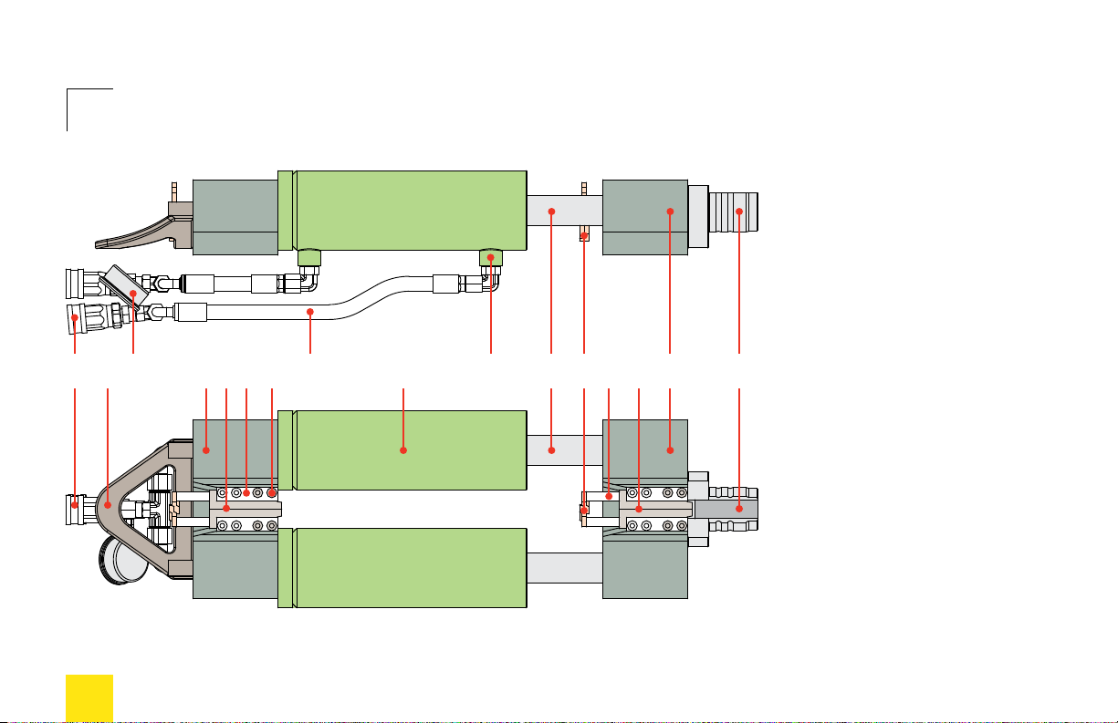
M50 ASSEMBLY
Hydraulic Fittings
Handle
Pressure Gauge
Pulling Bridge
Grippers (Pulling)
Cover Plates
Cover Plate Screws
Hydraulic Hose
Cylinder
Cylinder Port
Piston Shaft
Yokes
Yoke Towers
Grippers (Retaining)
Retaining Bridge
Nose
1
2
3
4
5
6
7
8
9
10
11
12
13
14
15
16
1 2 3 4 5 6 7 8 9 11 12 13 14 15 1610
7
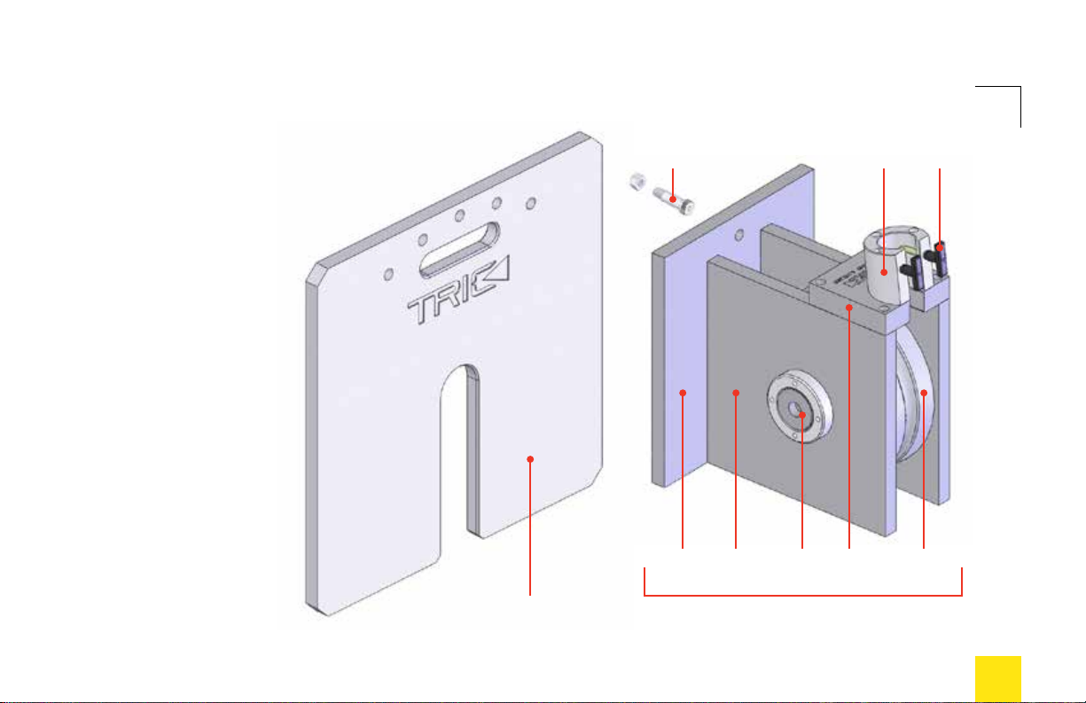
M50 ASSEMBLY
17 19
20 21 22 23 24
25 2618
17 Resistance Plate
18 resistance plate bolt
19 Pulley Base
20 front plate
21 side plate
22 axle
23 top plate
24 wheel (12”)
25 annulus
26 locking pins

8
M100 ASSEMBLY
Handle
Hydraulic Fittings
Yoke Assembly
Gripper Stop Screws
Cover Plates
Pulling Bridge
Grippers (Pulling)
Cover Plate Bolts
Cylinder
Piston Shaft
Gripper O-Ring Screws
Retaining Bridge
Grippers (Retaining)
Nose
1
2
3
4
5
6
7
8
9
10
11
12
13
14
1 2 3 5 6 7 8 94 10 1211 13 14
9
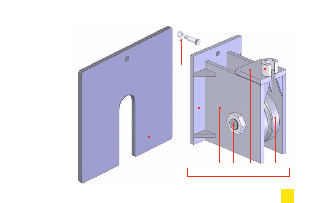
M100 ASSEMBLY
15 17
18 19 20 21 22
23
15 Resistance Plate
16 resistance plate bolt & nut
17 Pulley Base
18 front plate
19 side plate
20 axle
21 top plate
22 wheel (15”)
23 annulus
16

10
INTRODUCTION
e heart of every TRIC pipebursting system
is a cable-pulling device. Cable, or wire rope,
has been essential to the TRIC method since the
company introduced trenchless home sewer lateral
replacement in America back in 1996. Residential
sewers typically have directional changes between
the building foundation exit point and the property
line or municipal sewer main connection. A cable is
the best way to negotiate these bends. By contrast,
larger municipal sewer pipes generally maintain a
straight ow path, and each change of direction
becomes an accessible service point, or manhole.
TRIC equipment leverages the unique qualities of
steel cable to replace more pipe with less excavation,
especially in dicult easements and other hard-to-
access areas. is is also true for other underground
utilities such as water and gas.

11
Steel cable is valued for its exibility, compactness,
resiliency, and high strength-to-weight ratio. e
standard TRIC conguration employs a wheel that
directs cable and pulling force from horizontal (pipe
ow path) to vertical. is conguration allows for
great power in a relatively small footprint, and also
provides easier access to the puller and grippers.
As with all heavy-duty construction equipment, the
TRIC system must be used with caution and good
planning. e following pages illustrate the safe and
eective use of your TRIC M-Series pipebursting
system. Please review this information carefully.
NOTE: Your hydraulic power source (i.e., pump
or power-pack, PTO device, or excavation equip-
ment) is not covered in this manual. Please refer
to original manufacturers for further information.
INTRODUCTION

12
BURSTING SETUP
1Vitreous Clay
2Cast Iron
3Asbestos Concrete
4Reinforced Concrete
5Fiber Conduit
6Plastic
7Ductile Iron
8Steel
9Copper
BURSTING HEAD PIPE MATERIAL
Standard 1, 2, 3, 4, 5, 6
Impact 1, 2, 3, 4, 7, 8
Swaged Splitter 2, 6, 8, 9
Link-Blade Splitter 2, 6, 7, 8, 9
Figure 1
Bursting Head Selection Table

13
BURSTING SETUP
e rst step in any pipebursting job is to locate
and expose the existing pipe at each end of the
service line to be replaced. Drain lines should
be recently inspected and located by video, with
all depths, bends, transitions, connections, and
service points marked on the ground surface.
Entry and exit pits are congured dierently
from one another, and can have vastly dierent
excavation requirements. Figures 2 and 3 on the
following pages illustrate entry (launch) and exit
(pulling) pit congurations.
TRIC M-Series pipebursting units are designed
primarily to serve the municipal utilities market.
is includes underground sewer, water, and gas
lines in a variety of pipe materials ranging from
2” (50mm) to 20” (500mm) in diameter.
TRIC also manufactures a variety of bursting or
splitting heads, each specic to the type and size
of pipe to be replaced. Please see Figure 1 on the
opposite page for a selection of bursting heads to
replace dierent host pipes.

14
BURSTING SETUP
Figure 2
Entry or Launch Pit (Municipal)
a
b
a
c
30º
e
d

15
BURSTING SETUP
HDPE pipe is exible, which is indispensable
for pipebursting applications. e combination
of pipe diameter and wall thickness (known as
SDR or Standard Dimensional Ratio) deter-
mines the level of exibility for each pipe size.
A safe formula for the excavation of entry pits
for municipal sizes of HDPE pipe is a 30º access
angle or ramp down to pipe level. is translates
to a surface cut that is roughly twice as long as
the pipe is deep. Smaller pipe sizes (150mm and
under) have smaller bending radii. Figure 2 on
the facing page illustrates a typical municipal
entry scenario.
a= Variable
b= 2’ (60cm)
c= 6”–12” (15–30cm)
d= 36” (90–100cm)
e= 8”–12” pipe (200–300mm)
16
Figure 3
Exit, Receiving, or Pulling Pit (Municipal)
BURSTING SETUP
a
c
b
b
e
d
e

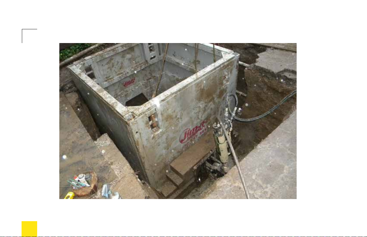
17
Municipal pipelines (especially drains and
sewers) generally require larger entry and exit
pits due to their size and depth. When using the
M-Series units (especially the M100), a trench-
box is indispensable for stabilizing the pulling
assembly, and for extracting the bursting head
at the end of the pull. Figure 3 on the opposite
page illustrates setup behind a trench box.
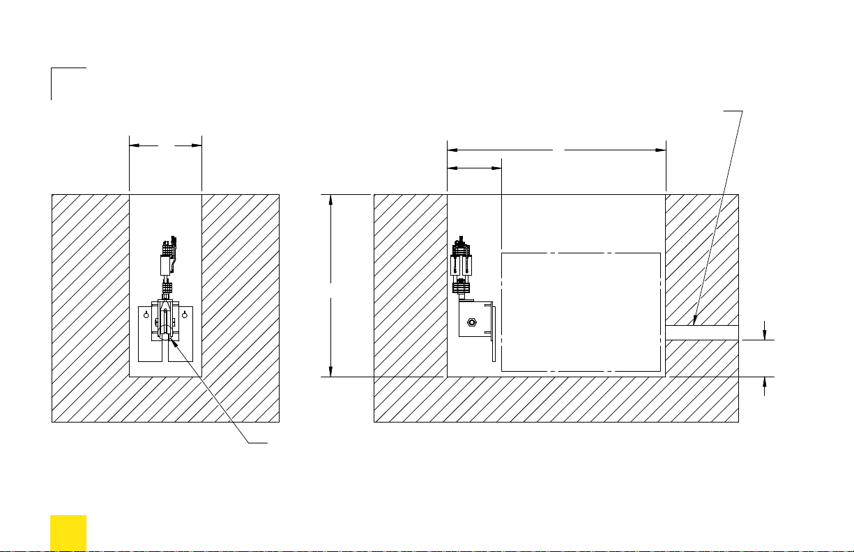
Figures 7 and 8 on pages 20 and 21 show typical
eld applications of the M50 and M100 in
conjunction with manhole boxes or heavy-duty
trench boxes.
BURSTING SETUP
a= 48” minimum (120cm)
b= Variable
c= 36” minimum (90–100cm)
d= 18”–24” (45cm–60cm)
e= 8”–12” pipe (200–300mm)

18
BURSTING SETUP
Figure 4
Inserting cable to upper grippers
Figure 5
Pulling cable slack to help insert cable to lower grippers
19
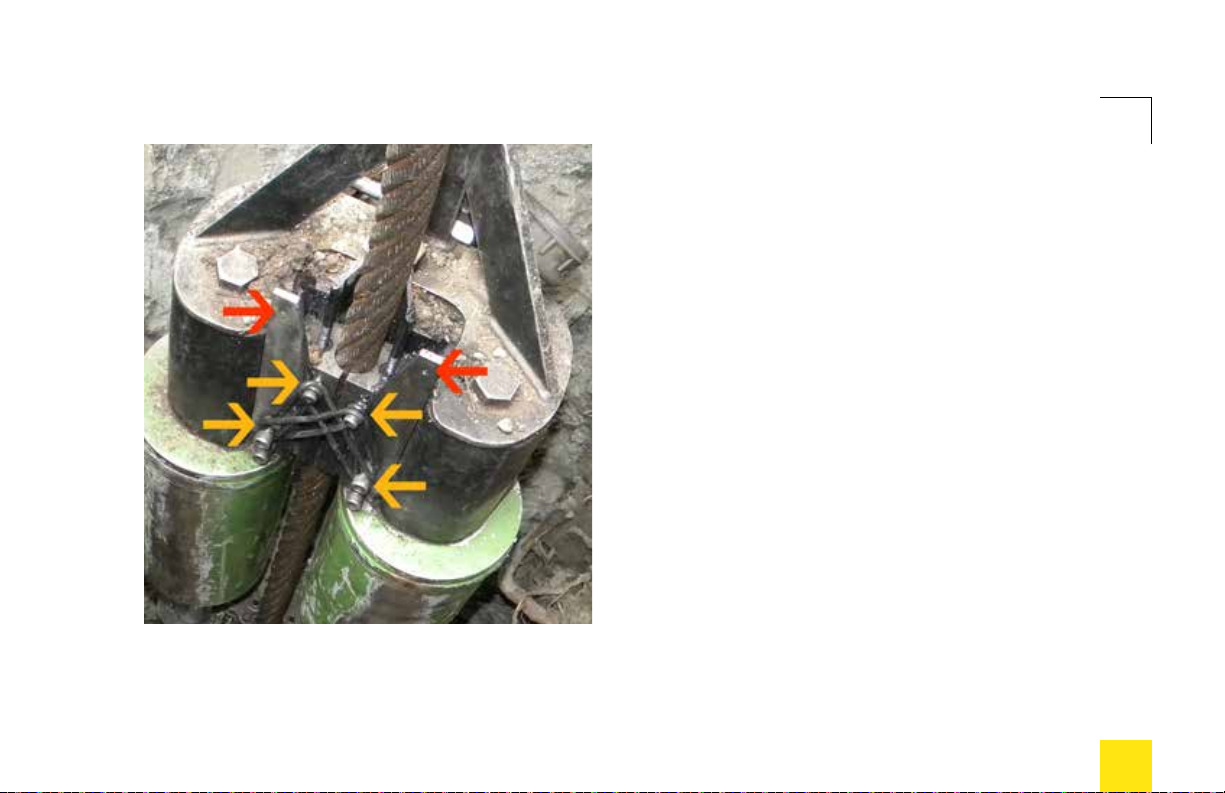
BURSTING SETUP
e M100 (shown here) is typically equipped
with either 1-1/8” (28mm) or 1-1/4” (32mm)
compact swaged wire rope. ese cable sizes
are much heavier than those used with TRIC
lateral systems. When loading the cable into
the M100, it is sometimes helpful to engage the
top (pulling) grippers rst, and then extend the
puller to draw slack out of the cable and bring
it into the lower or retaining grippers (Figures
4 and 5 on page 18). Also, the M100 may have
gripper stop-screws at the top of the cover plates.
In Figure 6 at left, red arrows indicate holes for
stop-screws (5/32” or 4mm allen-type), which
must be loosened or removed to allow full
opening of grippers to insert cable. When the
cable is fully engaged, attach gripper O-rings
to bolts on cover plates and grippers (yellow
arrows), to keep grippers engaged to the cable.
Figure 6
M100 gripper engagement
20
Figure 7
M50 with manhole box
BURSTING SETUP
This manual suits for next models
1
Table of contents
Other tricab Industrial Equipment manuals

Popular Industrial Equipment manuals by other brands


CARLO GAVAZZI
CARLO GAVAZZI SH2RODC224 instruction manual

S&C
S&C PureWave AVC Instructions for installation and operation

ZIEHL-ABEGG
ZIEHL-ABEGG ZA top SM200.15D Assembly instructions

Mecc Alte
Mecc Alte ECP3 Series Operating and maintenance instructions

TNA
TNA TX7302 Installation and operation manual

Mars
Mars Comfort-aire Century Compact HBH Series Installation operation & maintenance