656-500 8
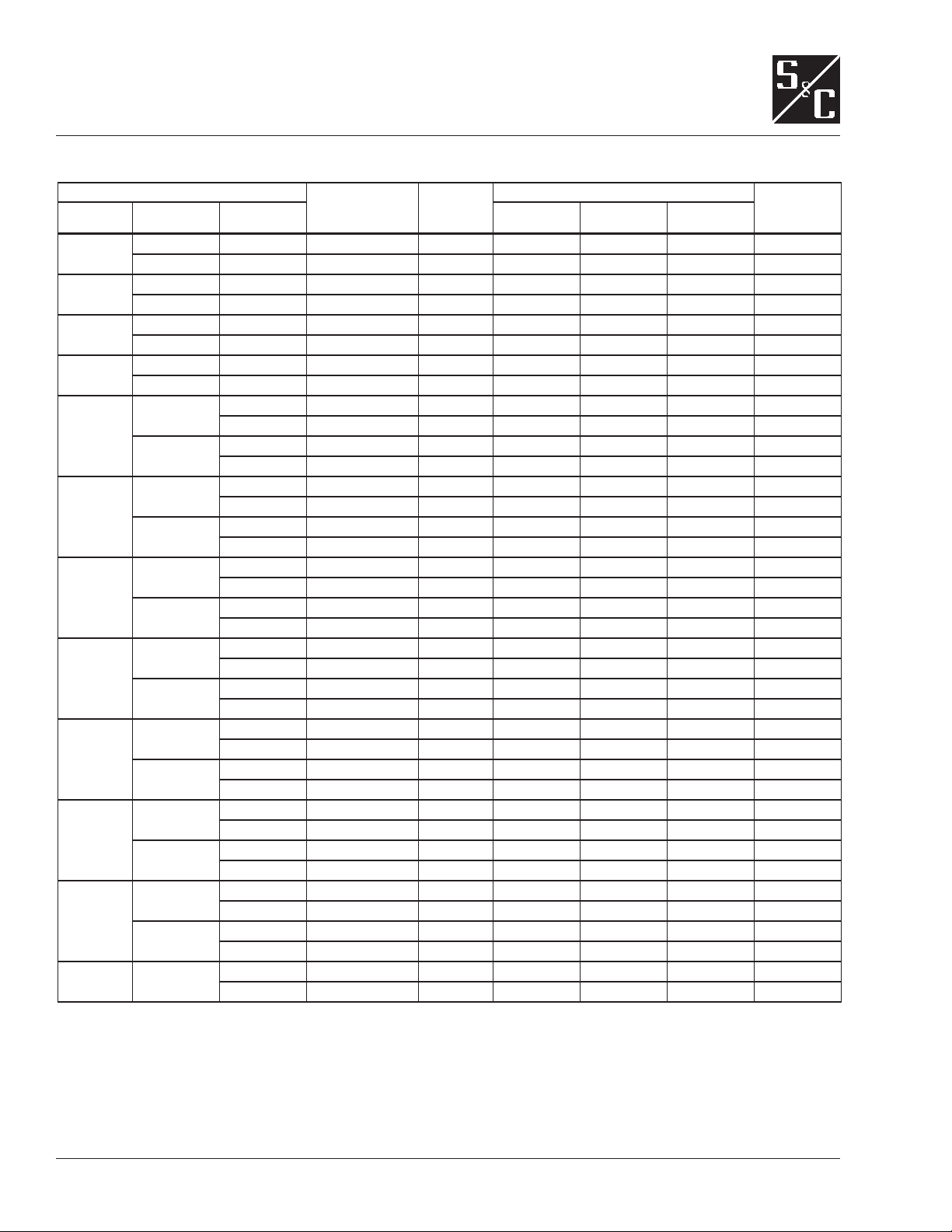
DIMENSIONS AND WEIGHTS
Section Dimensions and Weights
System Dimensions
L
D
H (in.)11
11
Number of
Sections
Approximate System Weight (lbs.) Total System
Weight (lbs.)
KVAR Voltage Stages Control
Section
Capacitor
Section 1
Capacitor
Section 2
500 480 3 87 37 121 1 6,000 — — 6,000
600 3 87 37 121 1 5,500 — — 5,500
625 480 3 87 37 121 1 6,500 — — 6,500
600 3 87 37 121 1 6,000 — — 6,000
750 480 3 87 37 121 1 7,500 — — 7,500
600 3 87 37 121 1 7,000 — — 7,000
1000 480 3 87 37 121 1 8,500 — — 8,500
600 3 87 37 121 1 8,000 — — 8,000
1250
480 3 174 37 121 2 7,000 2,500 — 9,500
4 174 37 121 2 7,000 2,500 — 9,500
600 3 87 37 121 1 9,000 — — 9,000
4 87 37 121 1 9,000 — — 9,000
1500
480 3 174 37 121 2 7,500 3,000 — 10,500
4 174 37 121 2 7,500 3,000 — 10,500
600 3 87 37 121 1 9,500 — — 9,500
4 174 37 121 2 7,000 2,500 — 9,500
2000
480 3 174 37 121 2 8,000 3,500 — 11,500
4 174 37 121 2 8,000 3,500 — 11,500
600 3 174 37 121 2 7,500 3,000 — 10,500
4 174 37 121 2 7,500 3,000 — 10,500
2500
480 3 261 37 121 3 8,500 4,000 3,500 16,000
4 261 37 121 3 8,500 4,000 3,500 16,000
600 3 174 37 121 2 8,000 3,500 — 11,500
4 174 37 121 2 8,000 3,500 — 11,500
3000
480 3 261 37 121 3 9,000 4,000 3,500 16,500
4 261 37 121 3 9,000 4,000 3,500 16,500
600 3 174 37 121 2 8,500 3,500 — 12,000
4 174 37 121 2 8,500 3,500 — 12,000
4000
480 3 261 37 121 3 9,500 4,000 3,500 17,000
4 261 37 121 3 9,500 4,000 3,500 17,000
600 3 261 37 121 3 9,000 4,000 3,000 16,000
4 261 37 121 3 9,000 4,000 3,000 16,000
5000
480 3 261 37 121 3 10,000 4,000 4,000 18,000
4 261 37 121 3 10,000 4,000 4,000 18,000
600 3 261 37 121 3 9,500 4,000 3,500 17,000
4 261 37 121 3 9,500 4,000 3,500 17,000
6000 600 3 261 37 121 3 10,000 4,000 4,000 18,000
4 261 37 121 3 10,000 4,000 4,000 18,000
1Height dimension includes outdoor fan. Height dimension with indoor fan is 108 inches. Height dimension with fan housing removed is 102 inches.