Tricel Vitae T3 UK5-14 User manual
TRICEL VITAE T3 UK6-14 tricel.co.uk 1
1013000 Rev 5 Dec 2023
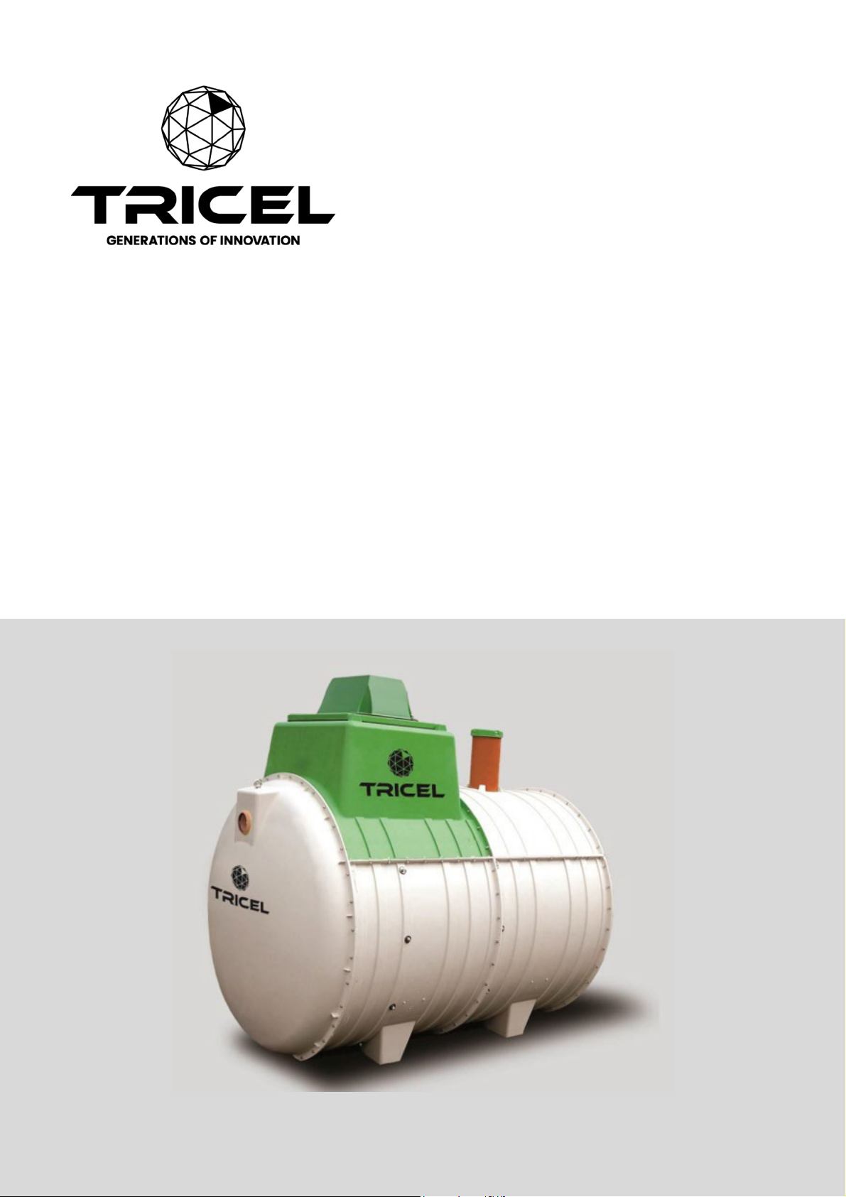
Tricel® Vitae T3 UK5-14
Wastewater Treatment Plants
Engineering a green future

TRICELVITEAT3UK6‐14TRICEL.CO.UK 2
Contents
1Health & safety precautions ........................................................................................................ 4
1.1 General ............................................................................................................................... 4
1.2 Electrical maintenance........................................................................................................ 4
1.3 Installation........................................................................................................................... 5
2Introduction: Tricel Vitae.............................................................................................................. 6
2.1 The Wastewater purification process ................................................................................. 6
3Tricel Vitae specification.............................................................................................................. 7
3.1 Typical Values .................................................................................................................... 7
3.2 Tank drawing ...................................................................................................................... 8
4Transportation & lifting ................................................................................................................ 9
4.1 Transportation..................................................................................................................... 9
4.2 Lifting .................................................................................................................................. 9
5
Installation
.............................................................................................................................. 10
5.1 Installation planning .......................................................................................................... 10
5.2 Inspection on reception of tanks....................................................................................... 10
5.3 Positioning and precautions ............................................................................................. 10
5.4 Types of installation .......................................................................................................... 11
5.5 Installation procedure: Tricel Tanks.................................................................................. 12
5.5.1
Excavation (dry & wet sites):
................................................................................12
5.5.2
Step by step – installation procedure
...............................................................13
5.6 Gravel specification .......................................................................................................... 14
5.7 Concrete specification ...................................................................................................... 15
5.8 Topsoil requirements ........................................................................................................ 15
5.9 Electrical requirements ..................................................................................................... 15
5.10 Risers................................................................................................................................ 16
5.11 Non-standard .................................................................................................................... 16
5.11.1
Alternative to concrete backfill (for wet sites without risers only):
... 16
5.11.2
Sloping ground:
.......................................................................................... 17
5.11.3
Proximity to rolling & static loads:
.......................................................... 17
5.12 Additional accessories...................................................................................................... 18
5.12.1
Grease trap
................................................................................................. 18
5.12.2
Sampling chamber
..................................................................................... 18
6
Commissioning
...................................................................................................................... 19
6.1 Control panel start-up ....................................................................................................... 19
7Disposal of treated water........................................................................................................... 19
8Maintenance.............................................................................................................................. 20
8.1 Regular maintenance........................................................................................................ 20
8.2 Annual maintenance......................................................................................................... 20

TRICELVITEAT3UK6‐14TRICEL.CO.UK 3
8.3 Annual service (available from your supplier) .................................................................. 20
8.4 Production of sludge ......................................................................................................... 21
8.5 Desludging (emptying the solid waste from the primary chamber) .................................. 21
9Operating conditions.................................................................................................................. 22
10
Troubleshooting
..................................................................................................................... 24
10.1 Odours .............................................................................................................................. 25
11
Certification
............................................................................................................................. 26
12 Terms & conditions .................................................................................................................... 29

TRICELVITEAT3UK6‐14TRICEL.CO.UK 4
1 Health & safety precautions
Reading the full technical manual prior to installation is important. Retain this document for
the lifetime of the product and in the event of a change of ownership of the site, transfer to
the new owner. As health and safety are of vital importance, the following aspects are
critical:
Precaution
Prior to installing, please consider the finished garden level. If you envisage that a
manhole riser/extension may be required to ensure manhole cover remains above
finished ground level, the plant must be installed with the appropriate excavation
foundation and backfill to accommodate the riser. Please refer to section 5.10,
‘Risers.’
1.1 General
It is important that all the information contained in this manual be always
adhered to.
Treated wastewater is not suitable for human consumption.
It is important that locks be fitted to the manhole cover to prevent accidental access.
Manholes are rated to maximum load of 125 kg.
Never enter a tank unless qualified to do so.
Do not use naked flames in the vicinity of the tank due to the danger of combustion.
The manhole covers shall never be left off an unattended tank. Always lock the
covers of the plant when work gets completed.
Sewage and sewage effluent can carry micro-organisms and gases harmful to
human health. Any person carrying out work on the Vitae must be appropriately
trained.
Suitable protective clothing: including gloves, goggles should always be worn.
Always remove contaminated clothing and protective equipment after working with
sewage treatment plants. Wash hands and face prior to eating, drinking, or
smoking.
Lock all manhole covers for safety
.
Tanks are supplied with three locking points, as
shown below. All points should be locked with a suitable locking device to prevent
unauthorized access
.
Locks do not come supplied.
1.2 Electrical maintenance
All electrical work is to be carried out by a qualified electrician using
suitable materials for the application.
Do not open the Tricel Vitae’s electrical unit cover without first isolating the mains
power.
Electrical work must be carried out strictly to the manufacturer’s instructions and
to the relevant national rules for electrical installations.
When working with machinery/electrical equipment, the proximity of water
shall be noted. Electrical
equipment shall not be wet when working with it.
There is the potential danger of falling into the tank during desludging while
manholes may be open – take all necessary safety precautions when
desludging.

TRICELVITEAT3UK6‐14TRICEL.CO.UK 5
1.3 Installation
Plan excavation work with due regard to health and safety requirements.
Excavated material should either be shored or battened back to a “safe” angle.
Use appropriate lifting equipment.
Take care around groundwork machinery.
Always keep proper footing and balance.
It is necessary to vent the Tricel Vitae at the inlet and the outlet of the plant.
TRICELVITEAT3UK6‐14TRICEL.CO.UK
6
2 Introduction: Tricel Vitae
Tricel Vitae wastewater treatment plants are manufactured from sheet moulding compound
(SMC) ensuring a durable and high-strength product. They are also constructed from modular
components; these modules are then fabricated together to make different size tanks.
SMC is a fiberglass-based compression moulded material used in applications that require
high strength and durability. The lightweight and compact design facilitates ease of installation
for domestic & light commercial applications up to 50PE.
The Tricel Vitae is well-suited for both domestic and light commercial purposes, employing
Submerged Aerated Filters (SAF) technology. SAF systems belong to the category of
biological treatment processes, creating a controlled environment that fosters the growth of
microorganisms. These microorganisms play a crucial role in breaking down organic
pollutants present in sewage and domestic effluents during the wastewater treatment
process.
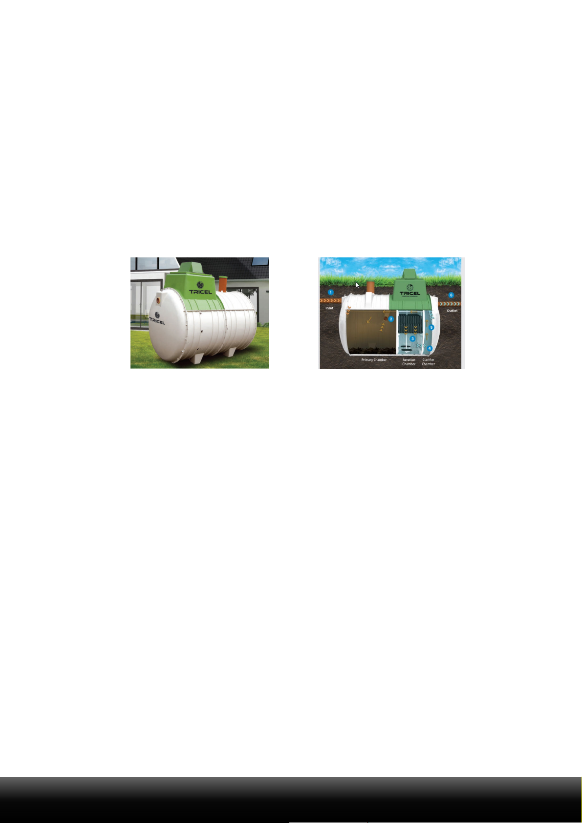
2.1 The Wastewater purification process
Stage 1
Wastewater from the dwelling, toilets, sinks, shower, etc., enters the plant.
Stage 2
Effluent enters the primary chamber which acts as a storage chamber to hold the wastewater
until it is ready to be treated. While being stored, the heavy solids settle to the bottom of the
tank and the light particles, like fats and oils, float to the top of the water to create scum. The
top layer acts as a seal and stops Odors from escaping. This chamber separates up to 70%
of the solids present.
Stage 3
Next is the aeration chamber, where masses of naturally occurring bacteria inhabit in a
specially designed Bio- Media filter. The bacteria feed on the waste removing it from the liquid.
A continuous supply of air from low-pressure, high-volume compressor in the top section of
the unit sustains these bacteria. Wastewater passes through the filter media repeatedly,
ensuring a very high treatment efficiency.
Stage 4
The wastewater then proceeds to the final settlement chamber. Any remaining minute
bacterial particles separate from the wastewater within this chamber before discharge from
the plant. This process slows the liquid’s velocity, allowing for any final trace impurities to
settle to the bottom of the tank. A timed sludge return system then returns these impurities to
the primary settlement chamber.
Stage
5
The remaining treated wastewater now meets the required standard and is safely passed out of
the Tricel Vitae plant. The treated effluent is now ready for discharge to a suitably designed
discharge area as required by the relevant local authority.
Stage
6
The Treated water is now passed to next level.

TRICELVITEAT3UK6‐14TRICEL.CO.UK 7
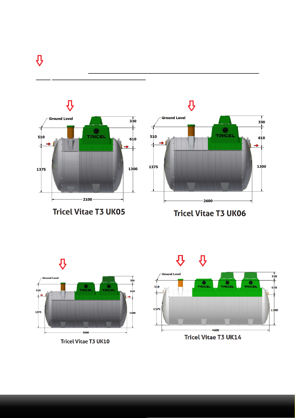
3 Tricel Vitae specification
3.1 Typical Values
Tricel Vitae: certified to EN 12566-3:2005
Tricel Vitae
UK5
UK6 UK10 UK14
Maximum treatment capacity
PE
5
6 10 14
Design flow rate (max)
litres/day
750
900 1500 2100
BOD load (max)
kg/day
0.3
0.36 0.6 0.84
Primary chamber volume
litres
1485
2300 3000 3675
Total
capacity
litres
3000
4000 5546 7176
Nominal Inlet pipe diameter
mm
110
110 110 110
Nominal Outlet pipe diameter
mm
110
110 110 110
Overall length
m
2.1
2.6 3.6 4.6
Overall width
m
1.64
1.64 1.64 1.64
Overall
height
m
2.24 2.24 2.26 2.26
Inlet invert to base
m
1.375
1.375 1.375 1.375
Outlet invert to base
m
1.3
1.3 1.3 1.3
Inlet invert to ground level
m
0.51
0.51 0.51 0.51
Outlet invert to ground level
m
0.61
0.61 0.61 0.61
Weight empty**
kg
270
300 400 500
No. of persons
1-
5
2-6 3-10 5-14
Air blower rating (mean)
W
64
64 100 64+100
Thickness (minimum)
mm
5
5 5 5
De sludge period (minimum)***
year
1-3
1.5-3 1-3 1-3
No. of Diffusers
Units
2
2 4 6
** Allow 100kg extra for lifting purposes
*** Depending on use & design value
TRICELVITEAT3UK6‐14TRICEL.CO.UK 8
3.2 Tank drawing
The arrow indicates an access point which must be opened to facilitate the desludging of
the primary chamber.
However, do not desludge the reactor/aeration chamber as this will
affect the treatment efficiency of the plant.
WARNING: care must be taken not to damage pipework when desludging the tank
TRICELVITEAT3UK6‐14TRICEL.CO.UK 9
4 Transportation & lifting
4.1 Transportation
Tanks must be held down during transportation using nylon straps, do not use
cables or chains to secure tanks. Do not over tighten straps that can result in
deformation of the tank shell. Do not drop or roll tanks from the truck.
Move tanks only by lifting and setting, do not drag or roll.
Always set the tank(s) on flat, smooth ground clear of debris. To prevent
movement, tanks may need to be tied down and chocked. Position the chocks in
the locations shown below:
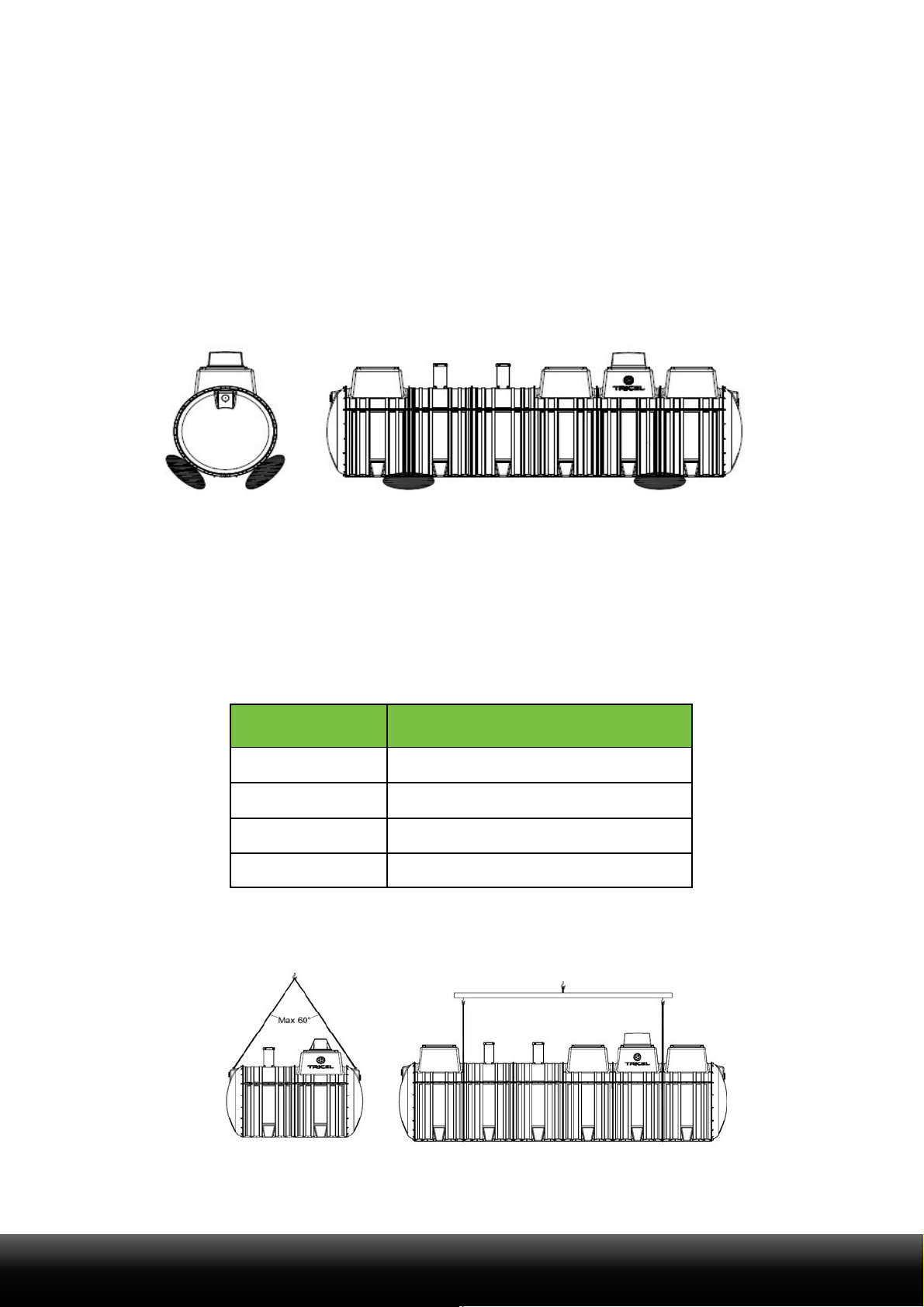
4.2 Lifting
A machine and webbing lifting straps best lift tanks – do not use chains or wire
ropes in contact with the tank.
Ensure tank is empty when lifting.
Tanks from one to four modules (4.6m) in length should be lifted using the eyebolts
on the tank. Ensure the angle between the slings is not greater than 60° when
lifting the tank. To ensure the angle is not greater than 60° the following sling
lengths are required:
Length of tank
Minimum length of the sling
2.1
2.1
2.6
2.6
3.6
3.6
4.6
4.6
Ensure sufficient lifting height can be achieved and is available on site. If not a lifting bar, as
per option two below, is required.
Option
1
Option
2

TRICELVITEAT3UK6‐14TRICEL.CO.UK 10
5
Installation
5.1 Installation planning
Important
Before the installation of the Tricel Vitae, it is important to read these instructions
carefully.
When planning the installation of a Tricel Vitae, you must consider the following:
Backfill considerations:
Is this a dry or wet site, i.e., the presence of a water table?
Which backfill material is appropriate for this site?
What will the finished ground level be, and will risers be required?
Site considerations:
Is the site restricted regarding area or height?
What is the topography of the site, i.e., being it sloping or flat?
What is the proposed depth of the installed tank to ensure the required slope
upstream?
Are static or rolling loads present on this site?
Only suitably qualified personnel should install the Tricel Vitae
.
Suitably sized equipment will be required to excavate the hole and to lift the Tricel
Vitae into place.
5.2 Inspection on reception of tanks
Visually inspect tanks for damage or fractures to the shell or ribs, de-laminations,
scratches, or abrasions deeper than 1.5mm, which may have occurred during
transport, prior to installation. Notify the delivery driver and/or your supplier of any
found. Do not attempt to carry out any unauthorised repairs, as this will invalidate
the warranty on the tank.
Once installed, Tricel cannot accept any claims for damage to the tank.
5.3 Positioning and precautions
The Tricel Vitae should not get installed in an area subject to flooding or excessive
water runoff as no flood waters should enter the tank.
The area around the Tricel Vitae should be adequately drained to permanently
remove groundwater and surface water from proximity to the tank.
The Tricel Vitae is not suitable to be used in water-logged sites where the groundwater
may rise above the inlet pipe.
When selecting the location of the Tricel Vitae, ensure that it is always accessible for
future maintenance.
The Tricel Vitae must be vented at the outlet and the inlet of the plant.

TRICELVITEAT3UK6‐14TRICEL.CO.UK 11
5.4 Types of installation
All installations must be “fit for purpose” to suit the on-site conditions, which will vary from site
to site. Ensuring this is the responsibility of the on-site contractor.
When installing a Tricel Vitae, there are two types of standard installation methods:
1. Gravel installation
2. Concrete installation
It is essential to consider two factors when determining which installation must be implemented:
1.
Is the Tricel Vitae being installed in a ‘dry site’ or a ‘wet site’?
A ‘
dry site
’ is a site in which the water table never rises higher than the
base of the tank.
A ‘w
et site
’ is a site in which the water table may rise higher than the base of
the tank but will not climb higher than the invert of the inlet. Where a higher
water level is present on site, ensure that the installation is suitable for the
site conditions.
Tricel strongly advises the installation of a vertical water table inspection pipe.
This inspection
pipe will facilitate convenient monitoring of the water table long
after the installation is complete.
Note: In difficult soils (e.g., clay with a high t-value), a site could be potentially classified as
wet if there is no drainage for surface water that enters the
excavation and it rises higher
than the base of the tank. The installer must determine this when selecting the correct backfill.
2.
Is a riser required (inlet invert >510mm from ground level), and if yes, what height riser
is necessary? (For more information on risers, please refer to section 5.10, ‘Risers’).
The following table specifies the required installation for on-site conditions:
Factors that determine the required installation
Installation
required
Type of site
Riser required
Dry
None
Gravel
Dry
250mm
Gravel
Dry
500mm & 750mm
Concrete
Wet
None
Concrete
Wet
250mm, 500mm & 750mm
Concrete
Important
- Incorrectly installed tanks that are subject to movement, rotation,
excessive loading or floatation may become damaged, for which Tricel
cannot accept liability.
- During installation, tanks must not be subjected to buoyant forces.
- Contact a qualified engineer if there are difficulties on site due to adverse
waterlogging.
-
Ballasting the tank is essential to avoid the tank from lifting when
backfilling.
TRICELVITEAT3UK6‐14TRICEL.CO.UK 12
5.5 Installation procedure: Tricel Tanks
5.5.1
Excavation (dry & wet sites):
5.5.1.1
Excavation:
length
&
width
Length and width of the excavation must exceed the dimensions of the Tricel Vitae by at least
500mm to maintain a minimum space of 250mm all around the tank.
Tricel Vitae
UK5
UK6
UK10
UK14
Tank length (m)
2.1
2.6 3.6 4.6
Tank width (m)
1.64
1.64 1.64 1.64
Excavation size (L x W) (m)
2.6 x 2.14
3.1 x 2.14 4.1 x 2.14 5.1 x 2.14
Note:
The size of the area for excavation applies to both dry and wet sites. However, unstable
ground
including regions with excessive sand, peat swamps, etc., may require larger
excavations. The excavation should be maintained dry by pumping or whatever suitable
means.
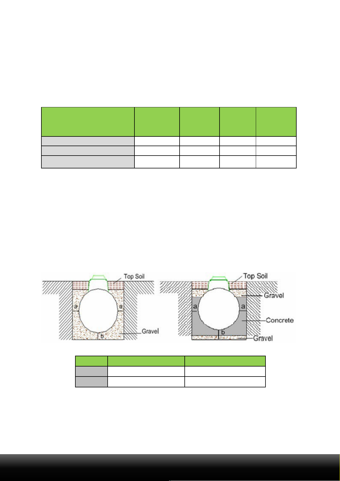
5.5.1.2 Excavation: depth
The inlet and outlet pipes determine the excavation depth, invert levels are relative to the
bottom of the tank and allowing for the minimum base thickness. Dimension details of the tank
provided on the relevant drawing; please refer to section 3, ‘Tricel Vitae Specification.’ Ground
instability,
e.g., running sand may necessitate over-excavation and stabilisation with hard core or
blinding concrete. The standard depth of the excavation for both gravel and concrete
installations are outlined as follows:
“a” minimum (mm)
“b” minimum (mm)
Dry
site
250
250
Wet
site
250
300
TRICELVITEAT3UK6‐14TRICEL.CO.UK 13
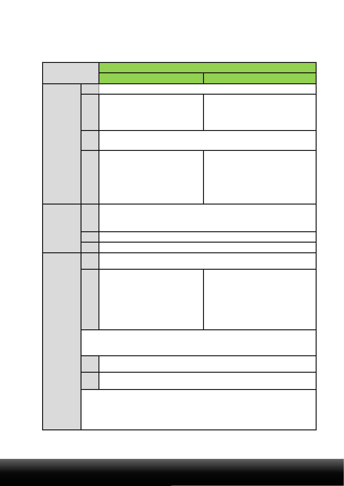
5.5.2 Step by step – installation procedure
Steps
Installation required (post-excavation)
Gravel
Concrete
Installation
of the tank
base:
1
Remove any soft spots or large stones and boulders.
2
The base is constructed of a
250mm layer of suitably
compacted gravel.
The base is constructed of a 50mm
layer of suitably compacted gravel,
covered with a 250mm layer of
semi-dry concrete.
3
Ensure that base is level and at the correct height to accommodate
the incoming pipework.
4
It is important to maintain a
completely dry excavation until the
final pour of concrete is set. It may
be necessary to line the excavation
with a continuous layer of 1200-
gauge polythene to maintain the
integrity of the concrete.
How to
position the
tank on to
the base:
5
Mechanically lift the plant carefully into the centre of the hole and
place on the prepared base.
6
The plant must sit level on the base.
7
Connect and seal the pipework to the tank.
Backfilling
around the
tank:
8
Ballast the plant by filling each chamber with clean water to a depth o
f
300mm and recheck the pipework levels.
9
Commence backfilling with gravel
in layers of 225mm evenly
around the tank ensuring that
there are no voids until gravel
has reached 50mm over the
cylindrical body of the tank.
Compact each layer in
succession. *
Commence backfilling with concrete
in layers evenly around the tank,
ensuring that there are no voids
until it has reached the outlet invert.
Continue backfilling with gravel,
until it has reached 50mm over the
cylindrical body of the tank. *
Note
* Continue filling the chambers with water while backfilling, ensure that the rising water
level is no more than 300mm above the backfill level.
10
Mount and seal manhole risers (if required). Please refer to section
5.10, ‘Risers.’
11
Complete backfilling with topsoil up to the max ground level. Allow for
subsequent settlement of topsoil.
Note
The use of geotextile barrier fabrics over the gravel backfill is considered good
installation practice. The fabric must be chosen to allow the flow of water in and out
of the excavation but to prevent the movement of fine soil particles into the gravel
backfill.

TRICELVITEAT3UK6‐14TRICEL.CO.UK 14
5.6 Gravel specification
Primary backfill specification:
Primary backfill material should be free-flowing granular material.
Compaction should be by lightweight rollers or vibratory plate. Compact gravel
evenly to ensure proper support for the tank. Make sure the vibrating machine
does not encounter the shell of the tank.
Tanks installations require primary backfill only within the region immediately
surrounding the tanks. This backfill must extend a minimum of 250mm outward from
the tank, and directly beneath the tank.
Backfill material shall not be frozen or contain lumps of frozen material at any time
during installation.
Use of other than specified backfill and bedding materials will void the tank warranty.
The following materials are approved as primary backfill:
Rounded pea gravel:
Minimum particle size 3mm, maximum 18 mm, compacted to a relative density of
>70%.
Gravel shall be clean and free flowing, free from large rocks, dirt, sand, roots,
organic materials, or debris.
Upon screening analysis, the backfill material shall have no more than 5% by
weight passing 2.36 mm sieve.
Or
Crushed or processed stone:
Minimum particle size 3 mm, maximum 12 mm, compacted to a relative density of
>40%.
Dry gravel density must be at least 1500 kg/m3. The material should be washed or
screened to remove fine particles.
Upon screening analysis, the backfill material shall have no more than 5% by weight
passing a 2.36 mm sieve.
Pea
Gravel Crushed Stone

TRICELVITEAT3UK6‐14TRICEL.CO.UK 15
5.7 Concrete specification
Semi dry concrete 25n grade with a ratio of 4.5 aggregate to 1 cement.
Important:
-
Do not use standard concrete mixes where sulphates or similarly aggressive
chemicals are present in the groundwater.
-
Lift height (rate of rise):
Determine the lift height (m), or rate of rise (m/h) for
the specific, concrete type used, to ensure that a design pressure (P max) of
15kN/m2 on the tank does not get exceeded.
-
Vibration:
The tank design assumes minimal compaction of the
surrounding concrete.
Where necessary, this may be extended to include
internal light vibration. Never use deep
revibrating which will substantially
increase the pressure on the tank, possibly causing failure.
-
Impact of concrete on discharge:
Under no circumstances should concrete
be discharged directly onto the tank.
5.8 Topsoil requirements
Clean native topsoil shall not contain rocks larger than 36mm on largest dimension.
5.9 Electrical requirements
Important
- Please ensure the electrical installation complies with all national
regulations and requirements
.
-
Electrical installations must be carried out by a qualified and certified
electrician.
- Please note different electrical requirements are dependent on the size of
the Tricel Vitae system, read the following sections carefully.
The customers’ minimum responsibility shall consist of:
A single run of 1.5mm² three core (two conductors plus earth conductor) steel
wire armoured (SWA) cable from the customer’s distribution cabinet to the tank unit
socket box.
Cable protection via10-amp MCB protected by (RCD), rated 230V, 30mA.
Bond the cable armour properly to the main earth at the premises.
Never disconnect the power to the air pump. It is imperative that it be running 24
hours a day, every day.

TRICELVITEAT3UK6‐14TRICEL.CO.UK 16
5.10Risers
If a Tricel Vitae requires a deeper than standard installation to align with the wastewater outlet
from the premises, manhole risers are available. These are to avoid the access cover being
positioning in a depression, as shown in the following diagram:
250mm, 500mm, and 750mm
risers are available for the Tricel Vitae if required
(requires installation suitable for the site conditions, please refer to section 5.4,
‘Types of installation’).
The Tricel Vitae is suitable for a manhole riser which gives a maximum inlet invert of
1260mm. However, the Tricel Vitae is not suited to areas where a more in-depth
installation is necessary.
Important:
-
Never place the manhole covers below ground level.
- Only use Tricel manhole covers and risers.
-
Do not allow ground water to enter the plant.
5.11Non-standard
5.11.1
Alternativetoconcretebackfill(forwetsiteswithoutrisersonly):
The option of securing the Tricel Vitae to a reinforced concrete slab or Deadman
anchor by way of straps may also be applied, as shown below:
Tricel accepts no responsibility for the design of the concrete slab/Deadman
anchor.
This solution should be designed by an on-site structural engineer to suit
site conditions.
If implemented, position the straps as close to the bolted joints as possible.

TRICELVITEAT3UK6‐14TRICEL.CO.UK 17
5.11.2
Slopingground:
When the slope of the ground is 5% or more, it is recommended to install a retaining wall to protect
the tank from the lateral thrust. Concrete backfill may also in some cases be sufficient to protect
the tank. A qualified structural engineer must determine if a retaining wall is required in the
presence of a steep slope as shown in the picture below:
5.11.3
Proximitytorolling&staticloads:
Minimum separation distances from:
Rolling loads (e.g., vehicle traffic): 4 metres
Static loads (e.g., dwelling house, shed): 3 metres.
If the tank installation is in an area where traffic or other superimposed loadings can be
applied, consult a structural engineer for the design of a reinforced concrete slab to prevent
any load getting transferred to the tank (or its concrete surround). If this slab is constructed
immediately above the tank, separate it from the surrounding concrete by a compressible
material.

TRICELVITEAT3UK6‐14TRICEL.CO.UK 18
5.12Additional accessories
5.12.1
Greasetrap
Best practice indicates that a grease trap gets fitted before the Tricel Vitae,
particularly in applications where high quantities of grease/oil exist in the
wastewater.
For the grease trap to continue to perform effectively, it must be
monitored/maintained on a regular basis and emptied when required.
Warning
If high levels of grease/oil are present within the Tricel Vitae, the plant will not
achieve the required treatment quality and it will reduce the lifespan of plant
components.
5.12.2
Samplingchamber
Best practice indicates that a sampling chamber is fitted after every Tricel Vitae to
allow easy access for sampling purposes.
Care should be taken to ensure that the sampling apparatus does not come into contact
with the pipework or walls of the sampling chamber to avoid contamination of the
sample.
Ensure that the outlet is installed high enough in the sampling chamber to allow for
the required sampling volume to be retained in the bottom of the sampling
chamber.
The inlet/outlet pipework installed in the sampling chamber must be minimum diameter
of 110mm.

TRICELVITEAT3UK6‐14TRICEL.CO.UK 19
6
Commissioning
Once tank installation, plumbing and the electrical connection are complete, the Tricel Vitae is
now operational. The plant should be filled with water during installation. If you have not, it should
be filled before its first use. If the plant is running correctly, you will hear a slight “hum” from the
air blower, and there will be air bubbles coming up evenly from the bottom of the aeration
chamber, rising to the surface.
The plant runs 24 hours a day, seven days a week all year round for optimum purification. In
periods of low occupancy, the sludge return system re-circulates the liquid in the plant ensuring
continuous performance. In periods of overload the sludge return plant passes the liquid back into
the primary chamber, so it passes through the aeration chamber again ensuring continuous
performance. It may take up to 13 weeks for the biomass to become fully established and to reach
optimum purification.
6.1 Control panel start-up
Connect the power cord from the control panel to the provided electrical socket. Once the
control panel is powered, you'll notice a humming sound from the blower, indicating that the
control panel and blower is operational.
7 Disposal of treated water
The treated wastewater from the Tricel Vitae should get disposed of as per guidelines from
the planning regulations issued by your local authority.
TRICELVITEAT3UK6‐14TRICEL.CO.UK 20
8 Maintenance
Warning
Any maintenance performed inside the tank represents a confined space.
Therefore, the maintenance person must be suitably trained to work in confined
spaces. Sewage and sewage effluent can carry micro-organisms and gases harmful
to human health. Only appropriately trained personnel can carry out maintenance
on the tank. Wear suitable protective equipment including gloves, goggles, etc.,
always. Always remove contaminated clothing and protective equipment after
completion of work. Wash hands and face prior to eating, drinking, or smoking.
Please refer to section 1, ‘Health & Safety precautions.’
A certain amount of plant maintenance is required on an on-going basis to ensure
that the plant is working correctly.
Ensuring this maintenance is the responsibility of the homeowner.
8.1 Regular maintenance
The vents around the base of the blower housing guarantee a fresh supply of air to
the air blower. All vents should be checked to make sure they are not blocked or
obscured.
Ensure that the plant is running correctly by removing the blower housing and
inspecting the display on the control unit.
Inspect the pipework for blockages if necessary. The inlet and outlet should be
inspected and rodded to remove any obstructions if necessary.
8.2 Annual maintenance
The Tricel Vitae will require a full service (available from your supplier) once a year
to guarantee the efficiency of the plant gets maintained. Accommodating service
personnel with clear access to the tanks is essential.
8.3 Annual service (available from your supplier)
During routine servicing, the following items get checked, if applicable:
All plant functions
The functionality of blower(s)
Blower pressures
Replacement of blower filters
Diffusers monitored to check for
dispersion of
air.
Inspection of Tricel covers and locks
Vents are clear of any blockages.
Clearing airlifts of any blockages
Measurement of the quantity and
condition of
bacteria in the aeration chamber
Measurement of sludge level in the
primary
chambers
Calibration measurement
Table of contents
Other Tricel Lawn And Garden Equipment manuals


Popular Lawn And Garden Equipment manuals by other brands


Texas Equipment
Texas Equipment GS 720 Li user manual

Kasco
Kasco 2400 Operation & maintenance manual

Allied
Allied 795 TSL Operator and parts manual

Ryobi
Ryobi RY15520 Operator's manual

Earth & Turf Products
Earth & Turf Products 100SP Operator's Manual with Parts List & Warranty

Essential Garden
Essential Garden S-PG11D1NK Use and care guide


