2
Table of Contents
1 Welcome! 2
2 Overview 4
3 Basic Functions Using the Thermostat 11
-HVACConguration 12
- System 17
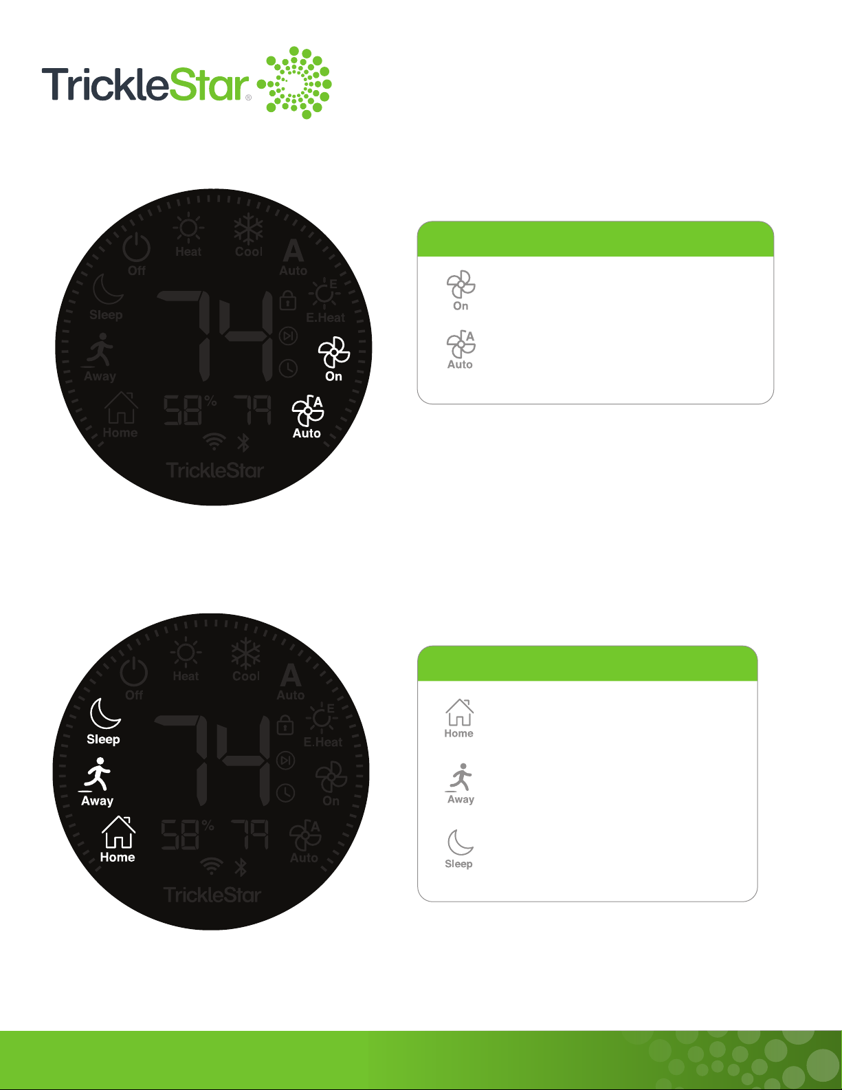
- Fan Mode 18
- Mode 19
-AdjustingtheSetTemperature 20
4 Advanced Functions Using the Thermostat via Portal/App 21
-ScheduleSettingsandScheduleHold 22
-InputLock 25
-HVACFanControls 26
-TakingOwnershipofaSmartThermostatRegisteredtoaDifferentuser 42
-ThermostatAdvancedSettings 48
5 Using the App 60
-AddingaNewDevice 61
-ControllingtheDevice 77
-SchedulingtheDevice 78
-CheckingtheDeviceInfo 79
-ConguringGeofenceSettings 80
-MiscellanousTabsintheMenu 84
6 Using the Portal 85
-UnderstandingtheIcons 86
-UsingtheIconsontheLeftColumn 87
-OntheDashboardPage(HomePage) 88
-OntheDevicesPage 89
-OntheVacationPage 91
-OntheGeofencePage 92
-Onthe3rdPartyIntegrationPage 93
7 Maintenance 94
8 Feature List 106