Trico FM-6 User manual

FM – 6
FERROGRAM MAKER
USER MANUAL
Revision D
August 2017
Trico Corporation
1235 Hickory Street
Pewaukee, WI 53072
Phone: 262.691.9336
www.tricocorp.com
Model:___________________________________
Serial Number:____________________________
Date of Purchase:__________________________
Windows Product Serial Number: ________________________________________

Page 2 of 36
Table of Contents
1. Introduction………………………………………………………………………. 4
1.1 Related Documentation…………………………………………………………4
2. Packing List and Assembly ……….……………………………………………... 5
2.1 FM-6 Unit Assembly…………………………………………………………... 5
3. Specifications and Operating Parameters………………………………………. 7
3.1 Physical Specifications………………………………………………………... 7
3.2 Power…………………………………………………………………………... 7
3.3 Unit Configuration……………………………………………………………... 7
3.4 Environmental Conditions……………………………………………………... 7
4. FM Nomenclature………………………………………………………………… 8
4.1 Major Components…………………………………………………………….. 8
4.2 Light Indicators....................................................................................................10
4.2.1 Station 1 and 2 Array Lights…………………………………………...10
4.2.2 System Indicators Lights……………………………………………….10
5. Consumables and Accessories…………...………………………………………………. 11
6. Fixer Pump Priming Procedure………………………………………………………… 12
7. Oil Sample Preparation…………………………………………………………...14
7.1 Fixer Filtered Solvent and Oil…………………………………………………..14
7.2 Dispensers……………………………………………………………………….14
7.2.1 Setting up Dispenser Assembly………………………………………... 15
7.2.2 Using the Pipette Dispenser……………………………………………. 15
7.3 Preparing Oil Sample……………………………………………………….......16
8. Run FM Procedures……………………………………………………………….17
8.1 Oil Samples for Testing………………………………………………………... 17
8.2 Initiating the FM-6……………………………………………………………...17
8.3 Shut Down Procedures………………………………………………………… 18
8.4 Operating Procedures…………………………………………………………...18
8.4.1 Automatic Cycle……………………………………………………….. 18
8.4.2 Semi-Automatic Cycle………………………………………………….21
8.4.3 Fixer Cycle……………………………………………………………...22
8.5 Clean Sample Analysis………………………………………………………… 22
9. Configuration……………………………………………………………………... 23
9.1 Post Sample Delay Cycle Time………………………………………………... 23
9.2 Fixer Dispensing Cycle Time………………………………………………….. 23
10. Tools and About Tab……………………………………………………………... 24

Page 3 of 36
11. Troubleshooting and Maintenance……………………………………………….25
11.1 Troubleshooting……………………………………………………………......25
11.2 Maintenance…………………………………………………………………... 28
11.2.1 Daily Maintenance or as Needed……………………………………… 28
11.2.2 Weekly Maintenance………………………………………………….. 28
11.3 Sample Tube Seal……………………………………………………………. 28
11.4 Over Flow Well…………………………………………………………….....29
11.5 Diagnostics…………………………………………………………………….29
11.5.1 Manual Sensor Checks………………………………………………..29
11.5.2 Using the Diagnostic…………………………………………………. 30
11.6 Bubble Level…………………………………………………………………..32
11.7 Calibration……………………………………………………………………..32
11.8 Pump Tube Pinching ………………………………………………………......33
12. Warranty………………………………………………………………………….. 34

Page 4 of 36
1. Introduction
The FM-6 Ferrogram Maker is a major component of Trico’s most advanced analytical Ferrograph
system. The FM-6 is more versatile, ergonomic and user friendly than its predecessors. Running on a
Windows 7 platform allows users to quickly upgrade software to the latest version, interface through the
internet, and set up e-mail capabilities. The USB connections can easily set up multiple pieces of lab
equipment together, connect to the user lab software or use peripheral devices such as the Ferroscope
camera. The provided Ethernet port allows users to network into their current systems.
The FM-6 instrument is designed with two independent stations to allow concurrent preparation of two
samples. Each station includes a holder to correctly position a sample slide over a magnetic field. The
FM-6 working in automatic mode, deposits a prepared fluid sample on the slide at a carefully controlled
rate. At the end of this sample deposition, a fixing solution washes the sample slide leaving only wear
particles and contaminants on the Ferrogram slide for analysis. Audio and visual signals indicate when the
Ferrogram is ready for microscopic evaluation on the Ferroscope.
The FM-6 can be operated in automatic, semi-automatic and manual modes. It offers several significant
advantages over its predecessor, the Dual Ferrograph, including automatic mode, reduced Ferrogram
production time, improved waste handling and fume venting. Configuration and settings can be changed
on the fly making it easier to control samples with different viscosities and to tune the unit for increased
production. An additional diagnostics feature helps to set-up and troubleshoot the unit.
1.1 – RELATED DOCUMENTATION
Trico offers the Wear Particle Atlas (P/N 76-0030) to support predictive maintenance efforts in helping to
identify wear particles. This Atlas is an encyclopedia of information exclusively involving wear debris
and measuring techniques. The Wear Particle Atlas is available with upgrade software versions. Contact
your dealer for further information. The User Manual is adequate for operating and maintaining the FM-6.

Page 5 of 36
2. Packing List and Assembly
The purpose of this section is to aid the user with the initial assembly procedures required when the FM-6
is first taken out of the shipping container. There are only a few steps that must be carried out.
The FM-6 is shipped in a single box which contains the following items:
1 – FM-6 unit 1 – O-ring Kits 1 – USB Mouse
1 – User Manual 2 – Vial Clips 1 – Waste Bottle
1 – Universal AC cord 1 – Fuse 1 – Luer Lock Syringe
1 – Fixer Priming Bulb
2.1 – FM-6 UNIT ASSEMBLY
To assemble the parts, follow these instructions:
1. Carefully remove the FM-6 unit from the box and place it on a hard level work surface or table to
support a load greater than 27 lbs (12 kg).
2. Locate the nameplate on the back panel. Record the serial number on the cover of the User
Manual for future reference.
3. Unpack the waste bottle and place the bottle into the waste bay by pressing the top right portion
of the door inward and allowing the door to open. Gently pull the waste cap from the bay and
thread the bottle onto the cap and tighten. Push the hose coming from the top of the waste bay
back into the unit and place the bottle into the cradle. Then close the waste bay door.
4. Place the fixer bottle into the fixer bay located on the right side of the FM-6 by tipping the bottle
and placing the tubing into the neck. Then position the bottle with the label facing outward into
the fixer bay.
NOTE: Not facing the label outward blocks the sensors and will give false indications.
5. Locate the universal AC cord and place the female IEC plug into the male socket on the FM-6.
6. On the bottom right side there is the sample pump vent barb, a 1/8” diameter line can be
connected to the barb and run to a vent hood if necessary to vent fumes.
7. Ensure the support feet under the waste and fixer bay are adjusted in the up position.
8. Place the male plug end into appropriate AC electrical outlet.

Page 6 of 36
9. Rotate the two adjustable feet located under the front of the unit clockwise or counter-clockwise
to level the unit. Two bubble levels are located between the magnet assemblies to indicate when
the unit is level.
10. Once the unit has been leveled, lower the two support feet that are located under the waste and
fixer bays until they make contact with the top of the countertop.

Page 7 of 36
3. Specifications and Operating Parameters
3.1 – P HYSICAL SPECIFICATIONS
Length (front to back) 14.00 in. 33.5 cm
Width (side to side) 12.00 in. 30.4 cm
Height 11.00 in. 27.9 cm
Weight (instrument) 27 lbs. 12 kg
3.2 – POWER
Voltage: 100-240V AC
Frequency: 50/60 Hz
Amperage: 1A
Instrument contains a 1A power fuse located at the power plug inlet.
3.3 – UNIT CONFIGURATUION
Operating system: Windows 7
Memory: 16 GB Flash
External USB Ports: 4 x USB “A”
Ethernet Connection: RJ45 cat 5
3.4 – ENVIRONMENTAL CONDITIONS
For indoor use on a solid level surface without movement or vibration.
Use in a well ventilated area.
Room temperature: 50ºF to 85ºF 10ºC to 29ºC
Humidity: 50% to 50% non-condensing
CAUTION: DO NOT operate the FM-6 with the back panel removed. Unplug the FM-6 from the power
supply before removing the back panel for fixer pump adjustments. Check with Trico before removing as
this could void the unit warranty. All other repairs must be done at the factory.
Page 8 of 36
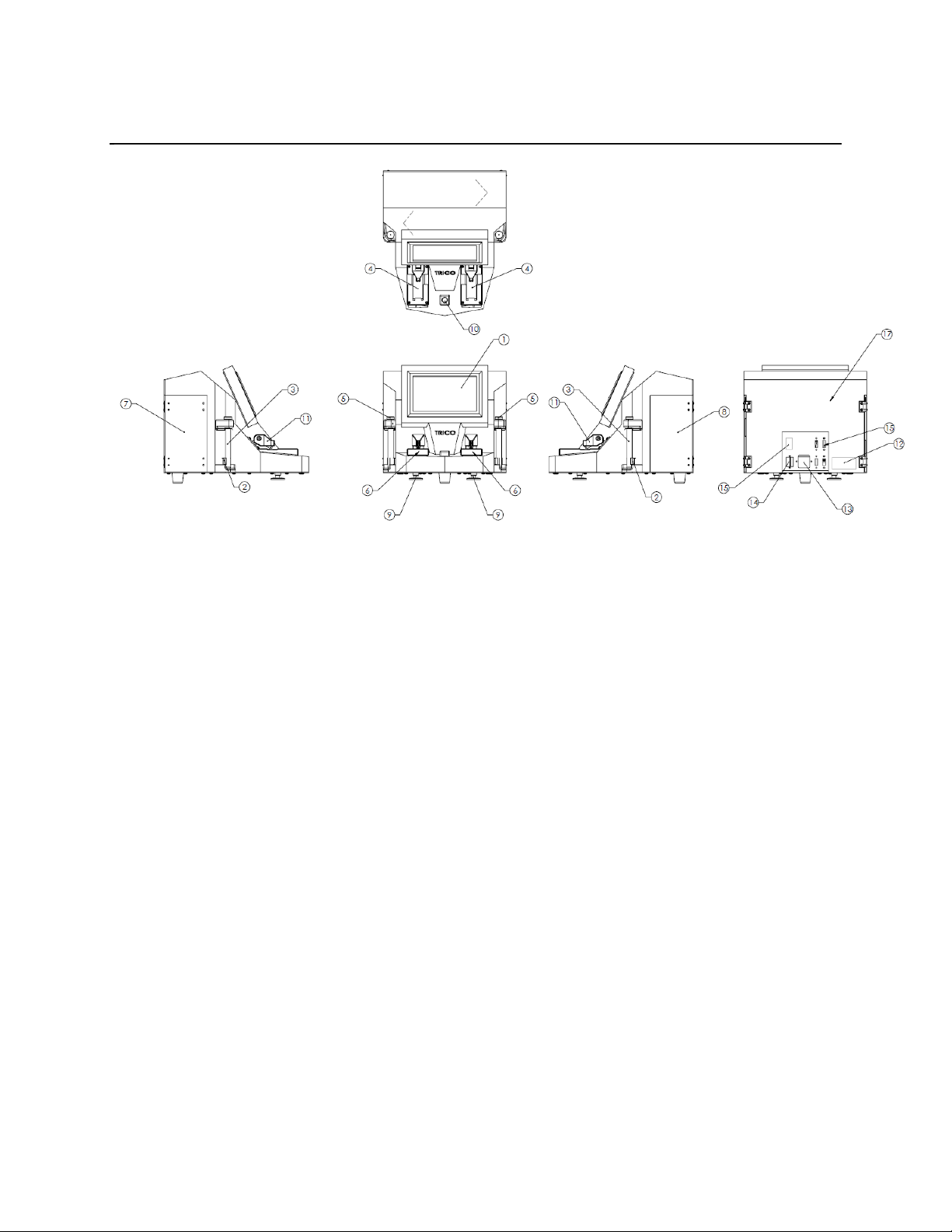
4. M Nomenclature
Figure 4.1
4.1 – MAJOR COMPONENTS
This section introduces the user to the major components of the FM-6 Ferrogram Maker. The following
subparagraphs discuss the major components, their location, and the nomenclature for each item on the
FM-6 Ferrogram Maker (refer to Figure 4.1).
1. LCD Screen: This displays the set-up and operational screens which has several options available
besides the calibration menu.
2. Vial Holder: Holds sample vials in place to make a seal with the sample head assembly. To maintain
clamping gently squeeze the vial holder prongs together. This part will eventually wear out and is
replaceable by unscrewing the two screws holding the clip to the vial holder and replacing the part.
3. Sample Vial: The sample vial contains the mixed lubricant sample and fixer/oil. It is a test tube that
holds slightly more than 7 ml. The vial is discarded after each test to avoid contamination.
4. Magnet Assembly: Magnets specifically designed to attract the ferrous particles to the glass substrate
that is positioned at a slight angle from the top of the magnet assembly to the bottom where the suction
head is located.
5. Sample Head Assembly: The sample head assembly is a multifunctional piece of hardware which
holds a sample vial and permits pressure to occur inside so that a constant sample flow rate is carried
across the glass substrate during the testing cycle.

Page 9 of 36
6. Test Area: The test area is a general term used to describe a grouping of components in or near the
particle removal area. It includes: magnet assembly, delivery arm assembly, slide lifter, and vacuum
drain (complete descriptions of each of these items are contained in Section 8, Run FM Procedures).
7. Waste Bottle: The waste bottle acts as a reservoir for sample fluid passing over the glass substrate. It
is installed on the left side of the FM-6 unit.
8. Fixer Bottle: The fixer bottle is located on the right side of the instrument and provides solvent to
both slide making stations. The Fixer Heptane (Heptane can be purchased from VWR at
https://us.vwr.com or call 1-800-932-5000) is filtered to a specified micron level to insure additional
particulate is not present on the sample Ferrogram. It is strongly suggested to use the fixer supplied by
Trico when running the FM-6 unit.
NOTE: Methanol is NOT compatible with the pumps in this unit.
9. Leveling Feet: Two adjustable leveling feet are located on the bottom front of the case and are used
to level the magnet assembly.
10. Bubble Levels: There are two bubble level indicators located between station one and station two
magnet assemblies. The horizontal level indicates adjustments made in the leveling feet along the X
axis while the vertical level indicates adjustments made by the leveling feet in the Z axis.
Adjustments should be made to move the center of the bubbles as closes as possible to the black
center mark line on the level bubble.
11. Dispensing Arm: The arm raises and lowers the dispensing assembly onto the glass substrate in
order to dispense fluid. When in operation, the arm is lowered and the sample tube is inserted into the
tube holder at the tip.
12. Model and Serial Number Label: When calling Trico Corporation for repair work on the FM-6, this
information will be needed.
13. Power Input Jack: The AC line socket accepts the 3-conductor IEC type AC line cord provided with
the FM-6 instrument.
14. Ethernet Network Jack: Ethernet cable can be used to utilize internet/intranet Windows 7 functions.
15. USB Ports: External peripheral devices such as the provided mouse, a keyboard or monitor may be
utilized through the USB connections provided as long as they are Windows 7 compatible.
16. On/Off Power Switch: The on/off power switch manually controls the 115/220 VAC input power to
the FM-6 instrument. Red indicates ON position, Black indicates OFF position.
17. Back Panel: Taking the back panel off allows the operator to access the fixer pumps and peristaltic
tubing. Check with Trico before removing this component to avoid voiding the warranty.

Page 10 of 36
4.2 – LIGHT INDICATORS
There are five types of light indicators located on the touch screen panel three of these are located in each
light array area for each station, two others are system indicators located in the middle of the screen. Each
light shows the status of a specific test operation. The lights are described in the following subparagraphs.
4.2.1 - Station 1 and 2 Array Lights
Sample Light: When the SAMPLE LED is lit green it indicates a sample vial is present and it is ready to
be dispensed onto the glass substrate. If there is no sample light indicated and the AUTO or SEMI buttons
are pushed the sample light will blink red indicating no sample vial is present. The sample light turns red
when the sample is in the progress of being dispensed and then turns black when empty.
Fixer Light: In each station array there is a fixer indicator, when lit yellow the FM-6 is pumping fixer
onto the glass substrate.
Complete Light: The complete light in each station array turns green when the entire cycle is finished
and the Ferrogram is ready for removal. Check the sample substrate to make sure that it is completely dry
before removing it from the magnet assembly.
4.2.2 – System Indicators Lights
Fixer Light: When the fixer light, located between the station array lights, is lit yellow, it indicates that
the fixer bottle is almost empty and needs replacement. When the fixer light is red the bottle is empty and
you can no longer run a FM-6 test.
Waste Full Light: When a waste bottle is near full the light indicator on the touch screen panel turns
yellow to indicate that it is almost time to empty the waste bottle. When full, the light turns red and no
more testing will be allowed until the waste bottle is removed and an empty bottle is properly
repositioned in the bay.

Page 11 of 36

Page 12 of 36
5. Consumables and Accessories
It will become necessary to reorder a number of consumables to continue testing on the FM-6 unit. This
section contains re-ordering information.
Many of the test equipment items should not be reused. Contaminated devices can cause inaccurate or
incorrect interpretation.
PN 73-0060 Sample Vials (Package of 250) – Disposable glass vials hold the oil and fixer and fit
properly into the vial holder.
PN 75-0020 Pipette Dispenser (Pipettor) – Used to draw oil samples for testing.
PN 73-0050 Pipette Tips (Package of 200) – Disposable tips used with the pipettor.
Heptane (Heptane can be purchased from VWR at https://us.vwr.com or call 1-800-932-5000) – A
filtered solvent used to thin the oil sample for testing and help eliminate breakage of the wetted barrier.
The fixer can be used to clean the magnet assemblies. This solvent is non-carcinogenic, but flammable.
PN 74-0020 Diluent Oil – Used to assist flow over the substrate and to thin heavily contaminated
samples to help prevent particle stacking on the substrate.
PN 74-0250 Grease Solvent – An agent used to dissolve grease into a form that can be used with the
FM-6 unit.
PN 73-0090 Sample Vial Rack – Holds up to 18 sample vials in preparation for testing.
PN 74-0060 Glass Substrate – A thin microscope slide specially treated with a Teflon barrier material to
keep the sample within the magnet path and guide the sample to the suction head.
PN 74-0280 Sample Tubes – Special length of tubing that maintains a seal at the vial head and transfers
the sample from the vial to the substrate located on the magnet.
NOTE: PN 73-0060, 74-0280 and PN 73-0050 must be discarded after one use in order to eliminate
cross-contamination.
CAUTION: Heptane and PN 74-0250 Grease Solvent are considered hazardous materials and should be
handled with caution and disposed of properly. Consult the Material Safety Data Sheets (MSDS) enclosed
with these chemicals for more information.

Page 13 of 36
6. ixer Pump Priming Procedure
Each fixer pump is primed and set to the proper flow rates at the factory before shipment. However, fixer
in the dispensing lines dissipates quickly and will require the operator to re-prime each line before
running Ferrograms on each station when the unit sits for prolonged periods of time.
After the FM-6 is set-up and ready to run, test the fixer pumps by pressing and holding the bottom button
on right and left side of the control panel marked FIXER. If after 60 seconds, the fixer doesn’t flow
follow the procedure below.
1. Press the DIAGNOSTICS tab which allows the user to turn on and off each of the mechanical
components of the FM-6.
2. Place a substrate slide onto station one and two.
3. Select the buttons for Fixer Pulse on station one and station two. This will run the fixer pumps
without holding the FIXER buttons on the RUN FM tab.
4. Allow fixer to be drawn from the fixer bottle into the pumps and into each line. This may take a
few minutes if both fixer lines are dry.
5. If no fixer is dispensed, open the fixer compartment door located on the right side of the machine
and remove the fixer bottle.
6. Using the fixer priming bulb, draw some fixer into the bulb from the fixer bottle.
7. Gently pull the fixer line out of the fixer compartment.
8. Insert one of the small tubes from the fixer line into the end of the priming bulb.
9. Elevate the priming bulb and gently squeeze fixer into the line until the fluid comes out one of the
lines located at the dispensing arm above the magnet assembly.
10. Turn off the fixer pump in correlation with the fixer line that was primed by pressing either
“Fixer 1 off” or “Fixer 2 off” on the DIAGNOSTICS tab screen.
11. Repeat the same procedure to prime the second line.
12. Once primed, insert the fixer line into the fixer bottle and place the bottle into the compartment.
13. Once fixer starts to flow from the dispensing arms onto the slides turn the waste pump on by
pressing the Waste ON button in the DIAGNOSTICS tab.

Page 14 of 36
14. Run the fixer pumps a few minutes until a constant flow of fixer is dispensing from each arm,
purging any bubbles trapped in the lines.
15. Press the Fixer OFF button in the DIAGNOSTICS tab for each station to turn the fixer off.
16. Allow the waste pump to run to remove any excess fixer from the slides; these slides can still be
used to collect samples.
17. Ensure that all components are reset by pressing the “All I/O off” button at the bottom of the
Diagnostics screen.
18. Select the RUN FM tab on the touch screen menu and follow the FM-6 procedures outlined in
this manual.

Page 15 of 36
7. Oil Sample Preparation
7.1 – FIXER FILTERED SOLVENT AND OIL
Fixer (a solvent passed through a 0.45 micron filter) is used to cut the lubricant sample for normal
operation. Its function is to loosen wear particles from gels that may form during periods of storage and
reduce sample viscosity so that it freely flows through the FM-6 sample tube (PN 74-0280). Trico
provides fixer in 400 ml bottles. Refer to Section 5, Consumables and Accessories for details.
Filtered oil (mineral oil passed through a 0.45 micron filter) is utilized to dilute the original sample which
may contain high concentrations of wear particles that pile up on the Ferrogram, thus masking their true
size and shape. For example, 9 ml of filtered oil added to 1 ml of sample produces a 10-to-1 dilution.
When filtered oil is used, testing is carried out in the normal manner. Trico offers filtered oil in 400 ml
bottles. Refer to Section 5, Consumables and Accessories for details.
7.2 – DISPENSERS
Dispensers are mechanical devices that draw fluid from a supply container and deliver measured amounts
to a test container. Two types are offered.
Dispenser Assembly: The dispenser assembly (refer to Figure 7.1) is used to extract fluid from the 400
ml fixer and filtered oil bottles. It accurately dispenses 1 ml into a test sample vial.
Pipette Dispenser: The pipette dispenser (refer to Figure 7.2) is used to extract fluids from the sample
bottle to place into a sample vial. It accurately delivers 1 ml of fluid. A disposable pipette tip, which
comes in contact with the fluid, fits on the pipette dispenser and is discarded after each test sample to
avoid contamination of subsequent samples.
Figure 7.1 – Dispenser Assembly Figure 7.2 – Pipette Dispenser

Page 16 of 36
7.2.1 – Setting Up the Dispenser Assembly
The Dispenser Assembly (PN 75-0010) is used with the 16 oz. (400 ml) bottles of fixer and diluent oil. It
accurately dispenses 1 ml of liquid with each stroke.
1. Open the dispenser assembly box and become familiar with the enclosed parts.
2. Thread the appropriate adapter to the top of the fixer or diluent bottle.
3. Measure the dip tube and cut to length so that it touches the bottom of the fixer or diluent bottle.
Insert the dip tube in the bottom of the dispenser assembly.
4. Thread the assembly on the fixer or diluent bottle with the adapter in place.
5. Fit the spout to the front of the dispenser assembly and tighten the nut to hold it in place.
6. Prime the dispenser assembly by pumping it several times to remove air bubbles. This step should be
done every time the pump sits overnight or longer.
7. The dispenser assembly is now ready to use.
7.2.2 – Using the Pipette Dispenser
The PN 75-0020 Pipette Dispenser has been calibrated by Trico to dispense one milliliter of liquid when
used according to the following directions.
1. Take the pipettor out of the box and become familiar with it. When pressing the plunger at the top of
the pipettor it has two stops. The first occurs when the plunger comes in contact with the plain sleeve.
This is the stop used when dispensing one milliliter of fluid.
2. This sleeve and the plunger can be pushed down further until the plunger knob hits the top of the
pipettor body.
3. For each new sample use, gently push a new pipette tip PN 73-0050 into the bottom of the pipettor.
Using a new tip used with each new oil sample will prevent cross contamination.
4. To draw a sample into the pipette tip, push the plunger all the way to the bottom of the stroke. Put the
tip into the liquid and slowly release the plunger. This will bring approximately 1.3 ml of liquid into
the tip.
5. To dispense 1.0 ml of liquid, slowly push the plunger to the first stop and hold it there until the liquid
stops dripping out of the pipette tip. Some liquid will remain in the pipette tip. This liquid can be
discarded or put back into the sample bottle by pushing the plunger down to the next stop.

Page 17 of 36
7.3 – PREPARING OIL SAMPLE
Gravimetric settling of wear particles in lubricating oil starts immediately after a sample is left standing.
To obtain a representative sample from a larger sample, the particles must be evenly dispersed. To make a
homogenous mixture, the following procedure is recommended:
1. The oil should be in a clear container to allow for observation of the oil and large contaminants. Make
sure the container is two-thirds full to allow for agitation to completely mix the particles into the oil,
thus giving the sample a homogenous mixture.
2. Heat the oil to approximately 150°F (65°C). This is according to ASTM standard procedure to keep
the particles suspended as long as possible.
3. Remove from the heat source and vigorously shake the bottle.
4. With the pipettor and clean pipette tip, remove 2 ml of oil and dispense into a clean sample vial.
5. Add 1 or 2 ml of fixer to the 2 ml of oil in the sample vial. The viscosity of the oil determines the
amount of fixer to add to the oil in the sample vial. For high-viscosity fluids add 2 ml of fixer to
reduce the viscosity. This will allow the viscous oil to flow along the glass substrate with ease. For
low-viscosity fluids 1 ml of fixer is enough to provide fluid flow on the substrate. It does not matter if
1 or 2 ml of fixer is used, as long as the required 2 ml of oil used for each test.
6. The quicker a sample is tested, the better the results. Allowing the sample to settle in the test vial may
cause bunching of particles on the substrate since the majority of material will be collected at the
bottom of the vial and deposited on the glass substrate first. To avoid this use the prepared sample as
soon as possible or re-mix the sample before testing so that wear particles are properly dispersed.

Page 18 of 36
8. Run M Procedures
8.1 – OIL SAMPLES FOR TESTING
Test samples should be obtained from the equipment based on the predictive maintenance program.
Specific collection techniques and suggested frequencies are suggested below.
•Always use approved glass or plastic sample bottles. Never use metal containers.
•Take samples from the machine while it is operating or no longer than 15 minutes after shut
down. Try to take each successive sample while the machine is operating under the same load.
•Take samples from the same point on the machine every time.
•Always take samples upstream from a filter.
•If using a sample valve, make sure stagnant oil is purged from the assembly prior to filling
sample bottle.
•Heat sample to 150ºF (65ºC) prior to testing.
•Special techniques are required to sample pipes and oil tanks. Please refer to the Trico Wear
Atlas for additional information.
8.2 – INITIATING THE FM-6
To initiate the FM-6, follow these basic procedures:
1. Press the on/off switch on the rear of the FM-6 unit to the on position. The sides of the switch
will indicate red, when the FM-6 is on. When the FM-6 is on Windows 7 will go through its start-
up operation and then the FM program will automatically boot. The RUN FM tab of the FM-6
screen will be shown.
2. Verify the FM-6 is level prior to running samples. Make adjustments where appropriate using the
leveling feet in front of the unit. Lower the support feet located under the waste and fixer bays for
additional support.
3. Place a full fixer bottle into the fixer bay located on the right side of the instrument by pressing
the door inward and allowing the door to open. Pull the door away from the magnet closure
assembly. When placing fixer bottle into position, gently put the Viton tubing through the neck of
the bottle and seat bottle into the cradle.
NOTE: Be sure when positioning the fixer bottle that the label is facing outwards to avoid false
low level readings indicated by the sensor behind the bottle.
4. Open the waste bay on the left side of the FM-6 and pull the suction cap assembly out.
5. Thread the waste bottle onto the cap and gently push the assembly into the waste bay.

Page 19 of 36
6. Check to make sure the waste bottle is in the proper position. Specific sample testing can now be
initiated as described in Section 8.4, Operating Procedures.
NOTE: Whenever changing the fixer, re-prime the pumping system by pressing the fixer buttons
on each station for 60 seconds to clear any air bubbles from the lines. Air bubbles trapped in the
fixer tubing can displace material on the glass substrate if not cleared from the system.
8.3 – SHUT DOWN PROCEDURES
1. Close FM-6 program.
2. Go to start menu in lower left corner and go to Windows shutdown command.
3. Allow Windows to completely shut down before turning off power to the unit.
4. Flip power rocker switch from red to black to turn power off.
8.4 – OPERATING PROCEDURES
The operating procedures are divided into three groups: automatic cycle, semi-automatic cycle, and fixer
cycle. Once a technician is familiar with these procedures, it is only necessary to follow the steps as a
refresher. All other information is background and of general interest.
8.4.1 – Automatic Cycle
The AUTO button initiates the flow of liquid across the Ferrogram at a controlled rate and automatically
switches to a rinse and drying cycle resulting in a completely prepared Ferrogram.
1. Preheat the sample to 150°F (65ºC +/- 5º), in the sample oven prior to testing.
2. Using a pipette dispenser, remove 2 ml of sample lubricant from the sample bottle and add it to a
new sample vial.
3. Using the dispenser assembly on the fixer/oil bottle, dispense 1 ml of fixer into the sample vial.
Depending on oil viscosity an additional 1 ml of fixer can be added to thin the solution creating 4
ml of solution.
4. Mix solution thoroughly by shaking vigorously with the opening closed or using a vortex mixer.
5. Raise the delivery arm assembly vertically corresponding to the station the sample vial will be
positioned in.
6. Insure the wire slide lifter is positioned down against the magnet assembly.
7. Unpack a glass substrate from its protective envelope.
8. Carefully, holding the glass substrate by the edges with the black circle located in the lower left
side of the glass substrate, place entry end of the glass substrate on the lip of the magnet assembly

Page 20 of 36
with exit end resting against the drain head (exit end is defined by the black dot). The glass
substrate should lie at the suction head and the upper end should be lying against the substrate
support ridge.
NOTE: The black circle viewed on the bottom left-hand side indicates the substrate is in the
proper position for sample lubricant to flow down the non-wetting barrier.
9. Lower the delivery arm until resting against rubber arm stopper.
10. Place the sample vial under the sample head assembly according to the station side of the magnet
assembly in which the test will run (refer to Figure 8.1).
11. Gently push the sample vial upward, inserting the o-ring seal in the top of the vial while seating
the vial tube in the vial clip holder at the bottom to seal it into position. A small amount of diluent
oil can be used to lubricate the o-ring seal prior to seating the vial.
12. Place a sample tube through the sample head assembly until it touches the bottom of the sample
vial (refer to Figure 8.2).
NOTE: Do not leave full sample tubes in opposite station if not running a test. Doing this will
close the valves for that station sample and pressure will build in the system. After a period of
time this pressure is great enough to force the entire sample out of the sample tube in seconds if a
test is initiated. If this situation occurs, remove the sample vial from the vial holder and the valves
will open relieving the pressure build up.
13. Push the other end of the sample tube through the end of the delivery arm, past the fixer delivery
tube until the sample tube touches the sub-straight (refer to Figure 8. 3). The fixer delivery tube
should be adjusted, prior, to just touch the sample tube.
14. Using a pen or small round object, gently push the slide against the suction hole in the vacuum
drain assembly. If the slide is too long and does not sit flat, replace with a new slide. If the slide is
forced in place the slide will shatter (refer to Figure 8.4).
15. Press the AUTO cycle button. This action starts initiating pumping of the sample. Once the
sample fluid is pumped over the substrate, the FIXER light comes on for eight minutes or the
time configured in the CONFIGURATION tab, indicating the fixer is now washing the glass
substrate. After pumping, the recommended 4 ml of solvent, the fixer wash pump stops and the
vacuum drain continues to run, removing any residual fixer and fumes until the Ferrogram is dry.
16. Sample completion is indicated when the COMPLETE cycle green light is on.
NOTE: The delay and fixer cycle time can be adjusted on the CONFIGURATION tab. See
Section 9, Configuration for details.
Table of contents
Popular Analytical Instrument manuals by other brands

Prostat
Prostat PGA-710B Getting Started Operations Guide

Co2meter
Co2meter GasLab SAN-102 user manual

Centech
Centech 67979 Owner's manual & safety instructions

Healthmark
Healthmark FIS-005 User manual & software installation guide

MasterForce
MasterForce 244-5968 Operator's manual

Delta-T Devices
Delta-T Devices SunScan SS1 user manual


