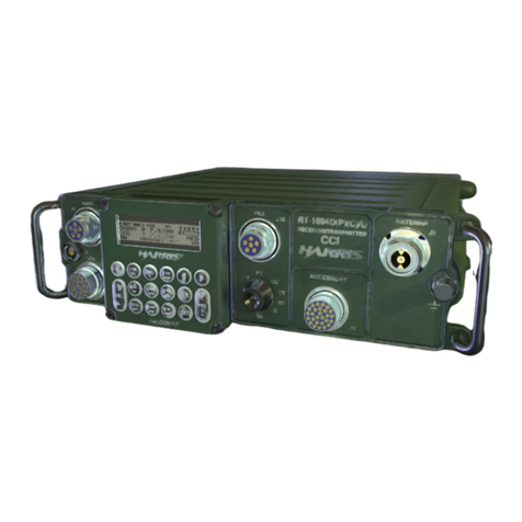
TriCom TCR-HHR-02 User manual

1
OPERATOR'S MANUAL
TCR-HHR-02 TACTICAL
REPEATER/COMMUNICATIONS SYSTEM
DOCUMENT # 90400-01223
Tricom Research, Inc. •http://www.tricomresearch.com
17981 Sky Park Circle, Suite M, Irvine, CA 92614 Ph:
(949) 250-6024 fax: (949) 250-6023

i
Revision History - Document
90400-01223 Revision Description Date
P1 Preliminary Release 20 Sep 2013
Note: The latest version of this manual can be downloaded from our website at
http://www.tricomresearch.com/downloads.html.
AUpdated 148 Radio portions 17 OCT 2016

ii
TABLE OF CONTENTS
Abbreviations and Glossary...........................................................................iv
Safety Summary.............................................................................................v
CHAPTER 1
GENERAL INFORMATION AND SAFETY INSTRUCTIONS
1 INTRODUCTION.........................................................................................1
1.1 Safety Precautions..........................................................................................1
1.2 Physical Description ......................................................................................1
1.3 Specifications.................................................................................................2
1.4 Equipment Provided.......................................................................................2
1.5 Controls and Indicators..................................................................................3
1.5 Controls and Indicators..................................................................................3
CHAPTER 2
OPERATING INSTRUCTIONS
2 INTRODUCTION .........................................................................................7
2.1 System Setup for Repeater Operation............................................................7
2.2 Setup for Communications System Operation...............................................14
2.3 Operation of Power Control...........................................................................14
CHAPTER 3
MAINTENANCE AND WARRANTY INFORMATION
3 INTRODUCTION .........................................................................................17
3.1 Preventive Maintenance.................................................................................17
3.1.1 Dirt and Dust..................................................................................................17
3.1.2 Oil and Grease................................................................................................17
3.1.3 Visual Inspections..........................................................................................17
3.1.4 Self-Test.........................................................................................................17
3.1.5 Power Out Checks..........................................................................................17
3.2 Corrective Maintenance.................................................................................18
3.3 Basic Troubleshooting Procedures ................................................................19
3.4 Warranty Maintenance...................................................................................19
3.5 Contact Information.......................................................................................20

iii
LIST OF TABLES
Table 1-1 Technical Specifications of the TCR-HHR-02........................................2
Table 1-2 TCR-HHR-02 Packing List......................................................................2
Table 1-3 TCR-HHR-02 Egress Panel.....................................................................3
Table 1-4 TCR-HHR-02 Power Amplifier Controls and Indicators........................4
Table 1-5 TCR-HHR-02 System Components.........................................................5
Table 1-6 TCR-HHR-02 Controls and Indicators....................................................5
Table 1-7 TCR-HHR-02 Power Control Module Indication Matrix........................6
Table 1-8 TCR-HHR-02 Battery Charger Indicators...............................................6
Table 1-9 TCR-HHR-02 Battery Charger Module Indication Matrix .....................6
Table 2-1 External DC Power Cable Pinout ............................................................15
Table 2-2 Power Control Matrix..............................................................................15
Table 3-1 Power Output Test ...................................................................................18
Table 3-2 TCR-HHR-02 Serviceable Parts..............................................................18
Table 3-3 TCR-HHR-02 Basic Troubleshooting Procedures...................................19
LIST OF FIGURES
Figure 1-1 TCR-HHR-02 Egress Panel.....................................................................3
Figure 1-2 TCR-MBA-50 WB Power Amplifier.......................................................3
Figure 1-3 TCR-HHR-02 System Components.........................................................4
Figure 1-4 TCR-HHR-02 Controls and Indicators....................................................5
Figure 1-5 TCR-HHR-02 Battery Charger Indicators...............................................6
Figure 2-1 Battery Charger Installation.....................................................................7
Figure 2-2 Radio Mount Locking Pin........................................................................7
Figure 2-3 RAD1 installed with retransmission cable connected .............................8
Figure 2-4 RAD1 and RAD2 Mounted with Retransmission Cable Installed...........8
Figure 2-5 AN/PRC-148 Bracket Position................................................................8
Figure 2-6 AN/PRC-152 Bracket Position................................................................8
Figure 2-7 Radio mount in horizontal position and locking pin in locked position..9
Figure 2-8 Egress panel vent .....................................................................................9
Figure 2-9 FAN enclosure vent .................................................................................9
Figure 2-10 TCR-HHR-02 Repeater System Signal Flow Block Diagram.................11
Figure 2-11 TCR-HHR-02 Communications System Signal Flow Block Diagram....12
Figure 2-12 Typical Tactical Repeater Setup..............................................................13
Figure 2-13 External DC Power Cable........................................................................15
Note: The information contained herein is for reference only and does not constitute a warranty
of performance.

iv
ABBREVIATIONS AND GLOSSARY
AGC Automatic gain control
ALC Automatic level control
AM Amplitude modulation
ANT Antenna
ANW2 Advanced Networking Wideband Waveform
BPS Bits per second
CT Cipher text
CW Continuous wave
COMSEC Communications security
dB Decibel
dBm Decibel referenced to 1 milliwatt (0 dBm = 1 mW)
FM Frequency modulation
Hz Hertz
IW Integrated Waveform
JITC Joint Interoperability Test Center (DISA)
kHz Kilohertz
LED Light emitting diode
LNA Low Noise Amplifier
LOS Line of sight
MHz Megahertz
mW Milliwatt
PT Plain text
PTT Push to Talk
RCV Receive
RX Receive
SATCOM Satellite Communications
SF Single Frequency
SRW Soldier Radio Waveform
TX Transmit
UHF Ultra-high frequency
VDC Volts, direct current
VSWR Voltage standing wave ratio
W Watt
WB Wideband
XMT Transmit

v
Safety Summary
The following are general safety precautions that are not related to specific procedures. These
precautions do not appear elsewhere in this manual. You must read and understand these
precautions before replacing, disassembling, or performing maintenance on the TCR-HHR-02
Tactical Repeater System.
DO NOT SERVICE OR ADJUST ALONE
Maintenance and operating personnel should not perform electrical or power measurements,
power-up, or servicing without the immediate presence of another person capable of rendering
aid.
RESUSCITATION
Personnel working with or near high voltages shall be familiar with the methods of artificial
respiration.
STANDARD GOOD PRACTICES
Personnel shall observe all standard practices when installing, replacing, operating, and testing
equipment (i.e., dry hands and clothing, remove personal jewelry, use rubber mats and other
insulating devices, etc.).
WARNING
Incorrect reassembly may result in a risk of electric shock or fire. To reduce risk
of electric shock, unplug the unit from outlet before attempting any maintenance
or cleaning. Turning off controls will not reduce this risk.
CAUTION
Use of an attachment not recommended or sold by the manufacturer may result in
risk of fire, electric shock, or personal injury.
To reduce risk of damage to electric plug or cord, pull by plug rather than cord
when disconnecting TCR-HHR-02.
Make sure cords are positioned so that they will not be stepped on, tripped over,
or otherwise subjected to damage or stress.
Do not operate the unit with damaged cable or connector. Replace damaged
cables or connectors immediately.
Do not operate the unit if it has received a sharp blow, been dropped, or otherwise
damaged in anyway; take it to a qualified serviceman.
Do not disassemble the unit; take the unit to a qualified serviceman when service
or repair is required.

1
CHAPTER 1
GENERAL INFORMATION AND SAFETY INSTRUCTIONS
1.INTRODUCTION.
This manual has been prepared by Tricom Research for the purpose of providing the user
information necessary to operate the TCR-HHR-02 Tactical Repeater/Communications
System.
a. Chapter 1 – General Information - provides safety and important information about
the TCR-HHR-02 Tactical Repeater System.
b. Chapter 2 – Operation - provides information necessary for operating the
TCR-HHR-02 and theory of operating procedures describing how the TCR-HHR-02
accomplishes its intended purpose.
c. Chapter 3 – Maintenance - provides information regarding TCR-HHR-02 preventive
care and corrective maintenance procedures.
d. Chapter 4 – Warranty Statement
The TCR-HHR-02 is a tactical repeater/communications system supporting the Harris
AN/PRC-152 (or AN/PRC-148 when this option is requested to the factory at time of purchase)
series Multi-band tactical radios as part of a man portable tactical radio system or as required
within part of other platform configurations. The TCR-HHR-02 shall meet the performance,
construction, quality, and environmental requirements to support effective tactical deployment
and use.
1.1. Safety Precautions.
This manual contains important safety and operating instructions for the TCR-HHR-02, review
the Safety Summary at the beginning of this Technical Manual.
Use of an attachment not recommended or sold by Tricom Research may result in risk of fire,
electric shock, or personal injury.
Make sure cords are positioned so that they will not be stepped on, tripped over, or otherwise be
subjected to damage or stress.
Do not operate the system with a damaged cable or connector, replace it immediately.
1.2. Physical Description.
The TCR-HHR-02 is contained within a rugged, water proof (when lid is closed and secured and
all vents are closed) thermoplastic transit case designed to withstand the harsh conditions
encountered in the tactical communications environment. All connections to electrical power,
data (PA remote only), audio and RF input/output are contained in an external jack panel located
on the right side of the unit (Refer to Figure 1-1). Two on-board Li-Ion batteries (not included)
provide backup power or can power the case for a limited amount of time, depending on usage
duty cycle, when external power is not available. Integrated fans allow operation with the lid
closed.

2
1.3. Specifications.
TCR-HHR-02 Technical Specifications are provided in Table 1-1.
Table 1-1 Technical Specifications of the TCR-HHR-02
Frequency Range 30–512 MHz
RF Output Power 25/50 Watts (power source dependant)
Input VSWR <1.5:1
Input/Output Impedance 50 Ohms (nominal)
Harmonics –60 dBc (typical)
Rx/Tx Isolation Antenna location and frequency dependent
AC Input 115/230 VAC (nominal), 47-63 Hz
DC Input 12-32 VDC
Battery BB-2590 (Li-Ion) (x2) & Battery Charger System
Size
Length 16 inches
Width 13 inches
Height 6.9 inches
Weight 30 lbs with batteries and radios
Operating Temperature –30°C to 60°C (when no batteries are used, battery type can
limit the operating temperature, refer to the battery
specifications for operating temperature range when using
internal batteries)
Environmental Splash Proof/Rain Resistant (when lid is closed and secured
and all vents are closed)
Construction Thermo Plastic Storm Case
Refer to TCR-MBA-50 WB Operator’s Manual for detail information on the specifications of the
Power Amplifier.
1.4. Equipment Provided.
The TCR-HHR-02 system ships with the components listed in Table 1-2.
Table 1-2 TCR-HHR-02 Packing List
Equipment Quantity
1
1
1
1
1
TCR-HHR-02 Tactical Repeater
AC Input cable
DC Input cable with terminal lugs
USB Cable (for PA remote)
CD with manuals and PA remote software

3
1.5. Controls and Indicators.
Figure 1-1 TCR-HHR-02 Egress Panel
Table 1-3 TCR-HHR-02 Egress Panel
1 RAD2-WB Antenna Port 6 RAD1 Antenna Port
2 AC Power Jack (115/230 VAC) 7 Vent
3 DC Input Power Jack (12/24 VDC) 8 PA Remote (Mini USB Jack)
4 RAD2-LOS Antenna Port 9 RAD1 Handset
5 RAD2-SAT Antenna Port 10 RAD2 Handset
1
23 6
5
4
7
8
9
10
11
12
13
Figure 1-2 TCR-MBA-50 WB Power Amplifier

4
Table 1-4 TCR-HHR-02 Power Amplifier Controls and Indicators
1 LOS Mode Select Button (toggles
between FM, AM, SINCGARS, HAVE
QUICK, WB and WB FH LOS modes)
8 Transmit LED Indicator
2 Power ON/OFF, RF Power Level and
LED Brightness Adjust Button 9 Fault LED Indicator
3 UHF SATCOM Mode Select Button
(toggles between SATCOM LNA OFF
and SATCOM LNA ON modes)
10 Remote LED Indicator
4 SATCOM Mode LED Indicator 11 AM Mode LED Indicator
5 WB Mode LED Indicator 12 Frequency Hopping Mode LED Indicator
6 SATCOM LNA ON Indicator 13 Line of Sight LED Mode Indicator
7 LED Indicator not used
Refer to TCR-MBA-50 WB Operator’s Manual for detail information on the operation of the
Power Amplifier.
9
8
7
11
1213
1
3
4
2
5 6
10
Figure 1-3 TCR-HHR-02 System Components

5
Table 1-5. TCR-HHR-02 System Components.
1 TCR-MBA-50 WB Power Amplifier 8 RAD2 Power Adapter/Mount
2 Cooling Fans (temperature controlled) 9 RAD1 Power Adapter/Mount
3 RAD2 RF Cable 10 Radio Strap
4 RAD2 Audio Cable 11 RAD1 RF Cable
5 BAT1 Charger and Battery 12 RAD1 Audio Cable
6 BAT2 Charger and Battery 13 AC-DC Power Supply
7 Radio Mount Locking Pin
2
1
3
4
5
6
7
Figure 1-4 TCR-HHR-02 Controls and Indicators
Table 1-6. TCR-HHR-02 Controls and Indicators
1 Power ON/OFF Button 5 BAT1 Cell B Status LED Indicator
2 System ON LED Indicator 6 BAT2 Cell A Status LED Indicator
3 External DC ON LED Indicator 7 BAT2 Cell B Status LED Indicator
4 BAT1 Cell A Status LED Indicator

6
Table 1-7. TCR-HHR-02 Power Control Module Indication Matrix
INDICATOR OFF ON OR FLASHING GREEN FLASHING RED
ON SYSTEM IS OFF SYSTEM ON N/A
EXT DC NO AC OR EXT DC
APPLIED AC POWER OR EXT 12-32
VDC APPLIED NO AC POWER OR EXT DC <12
VDC OR EXT DC > 32 VDC
B1-CELL A SYSTEM IS OFF B1-CELL A > 11 VDC B1-CELL A MISSING OR < 11 VDC
B1-CELL B SYSTEM IS OFF B1-CELL B > 11 VDC B1-CELL B MISSING OR < 11 VDC
B2-CELL A SYSTEM IS OFF B2-CELL A > 11 VDC B2-CELL A MISSING OR < 11 VDC
B2-CELL B SYSTEM IS OFF B2-CELL B > 11 VDC B2-CELL B MISSING OR < 11 VDC
Figure 1-5 TCR-HHR-02 Battery Charger Indicators
Table 1-8 TCR-HHR-02 Battery Charger Indicators
1 Cell A Charger Status LED Indicator
2 Charger ON LED Indicator
3 Cell B Charger Status LED Indicator
Table 1-9. TCR-HHR-02 Battery Charger Module Indication Matrix
MODE CHRG ON CHRG/FLT A CHRG/FLT B
CHARGER OFF OFF OFF OFF
CHARGER ON/PA IN TX MODE OFF OFF OFF
CHARGER ON/CHARGING ON GREEN ON YELLOW ON YELLOW
CHARGER ON/CHARGE COMPLETE ON GREEN OFF OFF
CHARGER ON FAULT ON ON RED ON RED

7
CHAPETR 2
OPERATING INSTRUCTIONS
2. INTRODUCTION.
This chapter will list in chronological order the steps necessary to operate the TCR-HHR-02
safely and efficiently in the repeater mode. The setup and operation for a communications
system is the same with the exception of the use of the retransmission cable.
2.1. System Setup for Repeater Operation.
Refer to Figures 2-8 and 2-9 for a system block diagram of the TCR-HHR-02 in repeater
configuration.
2.1.1 Install two BB-2590 batteries and secure the battery chargers to the batteries using
the Velcro strap as illustrated in Figure 2-1.
Figure 2-1 Battery Charger Installation
2.1.2 Connect 115/230 AC or 12/24 VDC power to the appropriate connector on the
egress panel (see Figure 1-1).
2.1.3 Unlock the radio mounting bracket by pulling on the locking pin and turning ¼ turn
cw or ccw (see Figure 2-2).
Figure 2-2 Radio Mount Locking Pin
Locking Pin in
Unlocked Position

8
2.1.4 Move the radio mounting bracket to the vertical position, install RAD1 first and
connect one side of the retransmit cable (see Figure 2-3).
Figure 2-3 RAD1 installed with retransmission cable connected
2.1.5 Install RAD2 and connect the other end of the retransmission cable (see Figure 2-4.
Figure 2-4 RAD1 and RAD2 Mounted with Retransmission Cable Installed
2.1.6 Move the radio support brackets to the appropriate position for the radio being used
(see Figure 2-4 and Figure 2-5, brackets should cover the radio type label for the radio
being used). Note: Moving the side brackets requires a 3/32 Allen wrench.
Figure 2-5 AN/PRC-148 Bracket Position.
(When 148 option is requested at time of
purchase)
Figure 2-6 AN/PRC-152 Bracket Position
RAD1 installed in vertical
position and retransmission
cable connected
Radio Support Brackets in
AN/PRC-148 position Radio Support Brackets in
AN/PRC-152 position

9
2.1.7 Turn on the system by pressing the power ON button (see Figure 1-4, DC and
battery power status LEDs will flash sequentially and fans will turn on for 5 seconds).
2.1.8 Move the radio mounting bracket to the horizontal position (see Figure 1-3) and
ensure the locking pin is engaged in the locked position (see Figure 2-6).
Figure 2-7 Radio mount in horizontal position and locking pin in locked position
2.1.9 Secure the radios with the Velcro strap as shown in Figure 1-3 (item 10).
2.1.10 Connect the RF and audio cables to the appropriate radio (cables are labeled RAD1
and RAD2).
2.1.11 Connect the receive antenna to RAD1 antenna port.
2.1.12 Connect the transmit antenna to RAD2 LOS antenna port.
2.1.13 If the system is going to be operated with the lid closed, open the vents on the
egress panel and on the fan enclosure assembly (see Figures 2-6 and 2-7).
NOTE: System is splash proof only when both vents
are closed and the lid is also closed and secured.
Figure 2-8 Egress panel vent Figure 2-9 FAN enclosure vent

10
2.1.14 Select LOS mode of operation and the appropriate RF power level (25 or 50 watts
power source dependent) on the TCR-MBA-50 WB power amplifier (refer to the
TCR-MBA-50 WB Operator’s Manual for information on how to setup the power
amplifier for LOS operation). The PA is setup for auto-on and should turn on whenever
external power is applied or when two charged batteries are installed and the system is
turned on.
2.1.15 Tune RAD1 to the receive frequency and the appropriate CTCSS tone squelch.
2.1.16 If a duplexer is not available, tune RAD2 to the transmit frequency (frequency
should be at least 15% higher than the receive frequency) and the appropriate CTCSS tone
squelch.
2.1.17 If a duplexer is not available, install the antennas with at least 50 feet of horizontal
separation or 10 feet of vertical separation.
2.1.18 Refer to Figure 2-9 and setup the field radios using the repeater for half-duplex
operation with the opposite frequencies as the repeater (the repeater’s receive frequency
must be the field radio’s transmit frequency and the repeater’s transmit frequency must be
the field radio’s receive frequency).
2.1.19 The system is now ready for repeater operation and retransmission operations can
begin.
NOTE: Repeater operation relies on the receive radio squelch
activation. Noise squelch should not be used in the repeater mode
as it is very susceptible to false activation of the repeater due to
interference. Continuous Tone-Coded Squelch System or CTCSS
squelch should be used instead for a more reliable repeater
operation.

11
DC POWER CONTROL
RAD1 RAD2
Figure 2-10 TCR-HHR-02 Repeater System Signal Flow Block Diagram

12
PELICAN CASE
ENCLOSURE
Figure 2-11 TCR-HHR-02 Communications System Signal Flow Block Diagram

13
50'
TX
Antenna RX
Antenna
Figure 2-12 Typical Tactical Repeater Setup

14
2.2. Setup for Communications System Operation.
Setup for Tactical Communications System mode is the same as the setup for the repeater mode
except that the retransmission cable is not used. Refer to Figure 2-11 for the signal flow diagram
of the TCR-HHR-02 in dual hand held radio communications system mode.
2.3. Operation of Power Control.
2.3.1 The order of precedence for power operation is AC, external DC and battery.
Switchover from one power source to the other is done automatically.
2.3.2 AC Power Operation – To operate the system using the internal AC-DC power
supply, simply plug a standard AC power cord to the AC input jack on the egress panel
(refer to Figure 1-1) and a 115/230 VAC, 47-63 Hz power source. The AC power supply
will provide 24 VDC for system operation as long as the AC power cord is plugged in
(refer to Table 2-1 for operating conditions when using the internal AC-DC power
supply). The 24 VDC is available from the AC power supply for battery charging and
radio operation even with the system turned OFF. This allows battery charging and radio
operation without having to turn the system ON. Turn ON the system by pressing the
PWR button to apply power to the TCR-MBA-50 WB Power Amplifier. The EXT DC
LED will flash green when AC power is applied and the system is ON. If AC power is
lost, the system will automatically switch over to external DC if available or to the internal
batteries.
NOTE: Switchover from AC to DC is uninterruptable if the external DC voltage is 24
VDC. Switchover to a 12 VDC external DC source or to internal batteries will reset the
system to reconfigure the TCR-MBA-50 WB Power Amplifier to battery or commercial
vehicle power mode.
2.3.3 External DC Power Operation – The acceptable external DC power voltage
range is 12-32 VDC. The EXT DC LED will flash GREEN if the external DC voltage is
within the acceptable range and the system is turned ON. Voltages below 12 VDC or
above 32 VDC will not power the system and will cause the EXT DC LED to flash RED.
As with AC power, the external DC power is available for battery charging and radio
operation whenever the external DC power is applied to the EXT DC jack on the egress
panel (see Figure 2-10 for external DC power cable information); however, the external
DC voltage must be in the 22-32 VDC range for the battery chargers to operate. When
operating from a 12 VDC or 24 VDC vehicle battery (vehicle engine turned OFF) and the
battery voltage drops to approximately 11 VDC for the 12 VDC battery or 21 VDC for the
24 VDC battery, the system will revert to internal battery mode and the EXT DC LED will
flash RED. Restarting the vehicle should return the system to full DC mode of operation
and the EXT DC should flash GREEN.
Table of contents
Other TriCom Conference System manuals
