TriCom TCR-HHR-05 User manual


ii
Table of Contents
Number Title Page
Abbreviations and Glossary........................................................................................................... iv
Safety Summary...............................................................................................................................v
Chapter 1 –General Information and Safety Instructions
1 INTRODUCTION ......................................................................................................1
1.1 Safety Precautions.......................................................................................................1
1.2 Physical Description ...................................................................................................1
1.3 Specifications..............................................................................................................2
1.4 Equipment Provided................................................................................................2-5
1.5 Controls, Connectors and Indicators.......................................................................6-9
Chapter 2 –Operating Instructions
2 INTRODUCTION ....................................................................................................10
2.1 System Setup.............................................................................................................10
2.2 System Operation......................................................................................................11
2.3 Power Amplifier Remote Control.............................................................................11
2.4 Radio Over IP (ROIP) Operation..............................................................................11
Chapter 3 –Maintenance and Warranty Information
3 INTRODUCTION ....................................................................................................13
3.1 Preventive Maintenance............................................................................................13
3.1.1 Dirt and Dust.............................................................................................................13
3.1.2 Oil and Grease...........................................................................................................13
3.1.3 Visual Inspections.....................................................................................................13
3.1.4 Self-Test....................................................................................................................13
3.1.5 Power Out Checks.....................................................................................................13
3.2 Corrective Maintenance............................................................................................14
3.3 Warranty Maintenance..............................................................................................14
3.4 Contact Information..................................................................................................15

iii
List of Tables
Number Title Page
1-1 Technical Specifications of the TCR-HHR-05...........................................................2
1-2 TCR-HHR-05 Equipment Included............................................................................2
1-3 AC Power Cable Pinout..............................................................................................3
1-4 Speaker Cable Pinout..................................................................................................4
1-5 AN/PRC-152 KDU/USB Adapter Cable Pinout ........................................................5
1-6 Auxiliary Power Output Jacks (5 VDC and 24 VDC) Pinout ....................................5
1-7 TCR-HHR-05 Egress Panel........................................................................................6
1-8 TCR-HHR-05 Power Amplifier Front Panel..............................................................7
1-9 TCR-HHR-05 System Components............................................................................8
1-10 TCR-HHR-05 Controls and Indicators.......................................................................9
3-1 Power Output Test ....................................................................................................14
3-2 TCR-HHR-05 Equipment Parts List.........................................................................14
List of Figures
Number Title Page
1-1 Equipment provided (Dual Net Handset, USB Cable, and Dual Net Speaker)..........3
1-2 AC Power Cable (Included) .......................................................................................3
1-3 Speaker Cable (Included)............................................................................................4
1-4 AN/PRC-152 KDU/USB Adapter Cable (Optional) ..................................................5
1-5 AN/PRC-152 KDU/USB Adapter Cable (1 included) ...............................................5
1-6 TCR-HHR-05 Egress Panel........................................................................................6
1-7 TCR-MBA-50 WB Power Amplifier Front Panel......................................................7
1-8 TCR-HHR-05 System Components............................................................................8
1-9 TCR-HHR-05 Controls and Indicators.......................................................................9
2-1 TCR-HHR-05 Signal Flow Block Diagram..............................................................12

iv
ABBREVIATIONS AND GLOSSARY
AGC Automatic gain control
ALC Automatic level control
AM Amplitude modulation
ANT Antenna
ANW2 Advanced Networking Wideband Waveform
BPS Bits per second
CT Cipher text
CW Continuous wave
COMSEC Communications security
dB Decibel
dBm Decibel referenced to 1 milliwatt (0 dBm = 1 mW)
FM Frequency modulation
Hz Hertz
IW Integrated Waveform
JITC Joint Interoperability Test Center (DISA)
kHz Kilohertz
LED Light emitting diode
LNA Low Noise Amplifier
LOS Line of sight
MHz Megahertz
mW Milliwatt
PT Plain text
PTT Push to Talk
RCV Receive
ROIP Radio Over IP
SATCOM Satellite Communications
SF Single Frequency
SRW Soldier Radio Waveform
UHF Ultra-high frequency
VDC Volts, direct current
VSWR Voltage standing wave ratio
W Watt
WB Wideband
XMT Transmit

v
Safety Summary
The following are general safety precautions that are not related to specific procedures. These
precautions do not appear elsewhere in this manual. You must read and understand these
precautions before replacing, disassembling, or performing maintenance on the TCR-HHR-05
Tactical Handheld Radio Communications Set.
DO NOT SERVICE OR ADJUST ALONE
Maintenance and operating personnel should not perform electrical or power measurements,
power-up, or servicing without the immediate presence of another person capable of rendering
aid.
RESUSCITATION
Personnel working with or near high voltages shall be familiar with the methods of artificial
respiration.
STANDARD GOOD PRACTICES
Personnel shall observe all standard practices when installing, replacing, operating, and testing
equipment (i.e., dry hands and clothing, remove personal jewelry, use rubber mats and other
insulating devices, etc.).
WARNING
Incorrect reassembly may result in a risk of electric shock or fire. To reduce risk
of electric shock, unplug the unit from outlet before attempting any maintenance
or cleaning. Turning off controls will not reduce this risk.
CAUTION
Use of an attachment not recommended or sold by the manufacturer may result in
risk of fire, electric shock, or personal injury.
To reduce risk of damage to electric plug or cord, pull by plug rather than cord
when disconnecting TCR-HHR-05.
Make sure cords are positioned so that they will not be stepped on, tripped over,
or otherwise subjected to damage or stress.
Do not operate the unit with damaged cable or connector. Replace damaged
cables or connectors immediately.
Do not operate the unit if it has received a sharp blow, been dropped, or otherwise
damaged in anyway; take it to a qualified serviceman.
Do not disassemble the unit; take the unit to a qualified serviceman when service
or repair is required.

1
CHAPTER 1
GENERAL INFORMATION AND SAFETY INSTRUCTIONS
1. INTRODUCTION.
This manual has been prepared by Tricom Research for the purpose of providing the user all
the information necessary to operate the TCR-HHR-05 Tactical Handheld Radio
Communications Set.
a. Chapter 1 –General Information - provides safety and important information about
the TCR-HHR-05 Tactical Handheld Radio Communications Set.
b. Chapter 2 –Operation - provides information necessary for operating the
TCR-HHR-05 and theory of operating procedures describing how the TCR-HHR-05
accomplishes its intended purpose.
c. Chapter 3 –Maintenance and Warranty Information- provides information regarding
TCR-HHR-05 preventive care and corrective maintenance procedures.
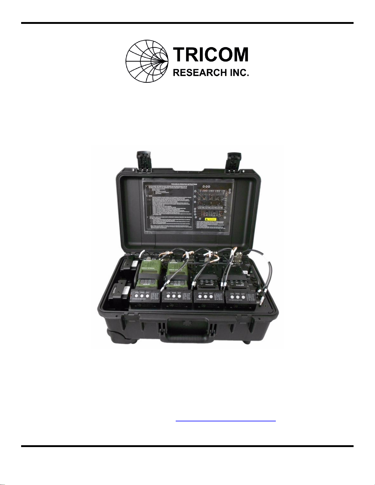
The TCR-HHR-05 is a tactical handheld radio communications system supporting four Harris
AN/PRC-152 or four AN/PRC-148 series multi-band tactical radio nets with integrated power
amplifiers as part of a man portable tactical radio system or as required within other platform
configurations such as vehicular or shipboard communications systems.
1.1. Safety Precautions.
This manual contains important safety and operating instructions for the TCR-HHR-05, review
the Safety Summary at the beginning of this Technical Manual.
Use of an attachment not recommended or sold by Tricom Research may result in risk of fire,
electric shock, or personal injury.
Make sure cords are positioned so that they will not be stepped on, tripped over, or otherwise be
subjected to damage or stress.
Do not operate the system with a damaged cable or connector, replace it immediately.
1.2. Physical Description.
The TCR-HHR-05 contains a pair of dual monolithic power amplifiers (two TCR-MBA-50 WB
power amplifiers in a single assembly) with an integrated RF switch that provides proper RF
routing to the antenna based on the mode of operation selected on the PA’s front panel (SAT,
LOS or WB); each dual power amplifier assembly has a dedicated power supply. The front
panel of each power amplifier has been remoted and integrated with the radio’s power
adapter/mount for easy access. The system is contained within a rugged, water proof (when lid is
closed and secured) thermoplastic transit case designed to withstand the harsh conditions
encountered in the tactical communications environment. All connections to electrical power,
data (USB and KDU only with optional cable adapters), audio and RF input/output are contained
in an external jack panel located on the rear side of the unit (Refer to Figure 1-6). Temperature
controlled integrated fans provide air cooling for the internal components.

2
1.3. Specifications.
TCR-HHR-05 Technical Specifications are provided in Table 1-1. Refer to the TCR-MBA-50
WB Operator’s Manual for more detailed information on its technical specifications.
Table 1-1 Technical Specifications of the TCR-HHR-05
Frequency Range
30–512 MHz (applicable to all four TCR-MBA-50 WB Power Amplifiers)
RF Output Power
25/50 Watts (applicable to all four TCR-MBA-50 WB Power Amplifiers)
Input VSWR
<1.5:1 (applicable to all four TCR-MBA-50 WB Power Amplifiers)
Input/Output Impedance
50 Ohms (nominal, applicable to all four TCR-MBA-50 WB Power
Amplifiers)
Harmonics
–60 dBc (typical, applicable to all four TCR-MBA-50 WB Power
Amplifiers)
Rx/Tx Isolation
Antenna location and frequency dependent
AC Input Range
90-264 VAC, 47-440 Hz
Size
Length
21.7 inches
Width
14.1 inches
Height
8.9 inches
Weight
59 lbs without radios
Operating Temperature
–30°C to 60°C
Environmental
Splash Proof/Rain Resistant (when lid is closed and secured)
Construction
Thermo Plastic Case
1.4. Equipment Provided.
The TCR-HHR-05 system contains the equipment listed in Table 1-2.
Table 1-2 TCR-HHR-05 Equipment Included
Equipment
Part Number
Quantity
TCR-HHR-05 Tactical Handheld Radio Communications Set
11000-00831
1
TCR-HHR-05 Quick Reference Guide
90400-01230
1
TCR-HHR-05 Operator’s Manual
90400-01233
1
AC Power Input Cable
77500-00614
1
USB Cable (for PA remote control and radio data)
77500-00450
1
TCR-SPK-02 Dual Net Amplified Speaker
11000-00771
2
TCR-SPK-02 Speaker Interface Cable
77500-00615
2
Dual Net Handset
79000-00503
2
CD with TCR-HHR-05 system manual, TCR-MBA-50 Power
Amplifier manual, TCR-SPK-02 Amplified Speaker manual
and TCR-MBA-50 remote software
1
3
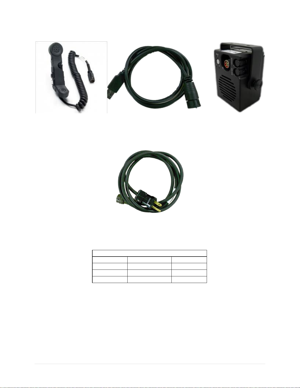
Figure 1-1 Equipment provided (Dual Net Handset, USB Cable, and Dual Net Speaker)
Figure 1-2 AC Power Cable (Included)
Table 1-3 AC Power Cable Pinout
CONNECTION
73200-00704 77216-96011
A
B GREEN
WHITE 73100-00598
B
A
C BLACK C
4
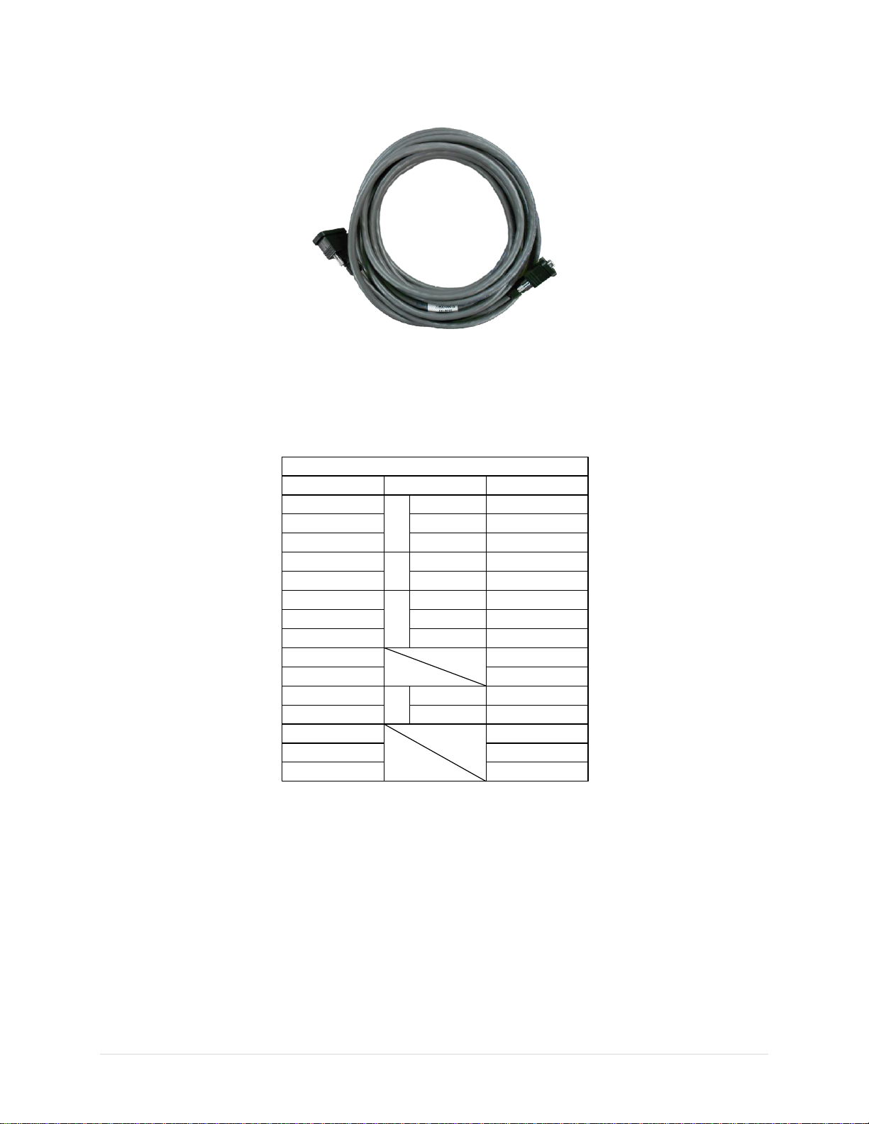
Figure 1-3 Speaker Cable (Included)
Table 1-4 Speaker Cable Pinout
CONNECTION
73100-00584 77624-00001
8, EXT_GND
6, RADIO B IN BROWN
SHIELD
7, PTT_B BLACK
5, TX_B WHITE
4, TX_A
2, RADIO A IN BLUE
BLACK
3, PTT_A BLACK
1, EXT_GND SHIELD
9, BIAS_A
10, BIAS_B
11, 28VDC GREEN
12, GND BLACK
13
14
15
73200-00683
1
2
3
4
5
6
7
8
9, NC
10, NC
11
12
13, NC
14, NC
15, NC
PAIR 2
PAIR
3
PAIR 4
PAIR
6
5
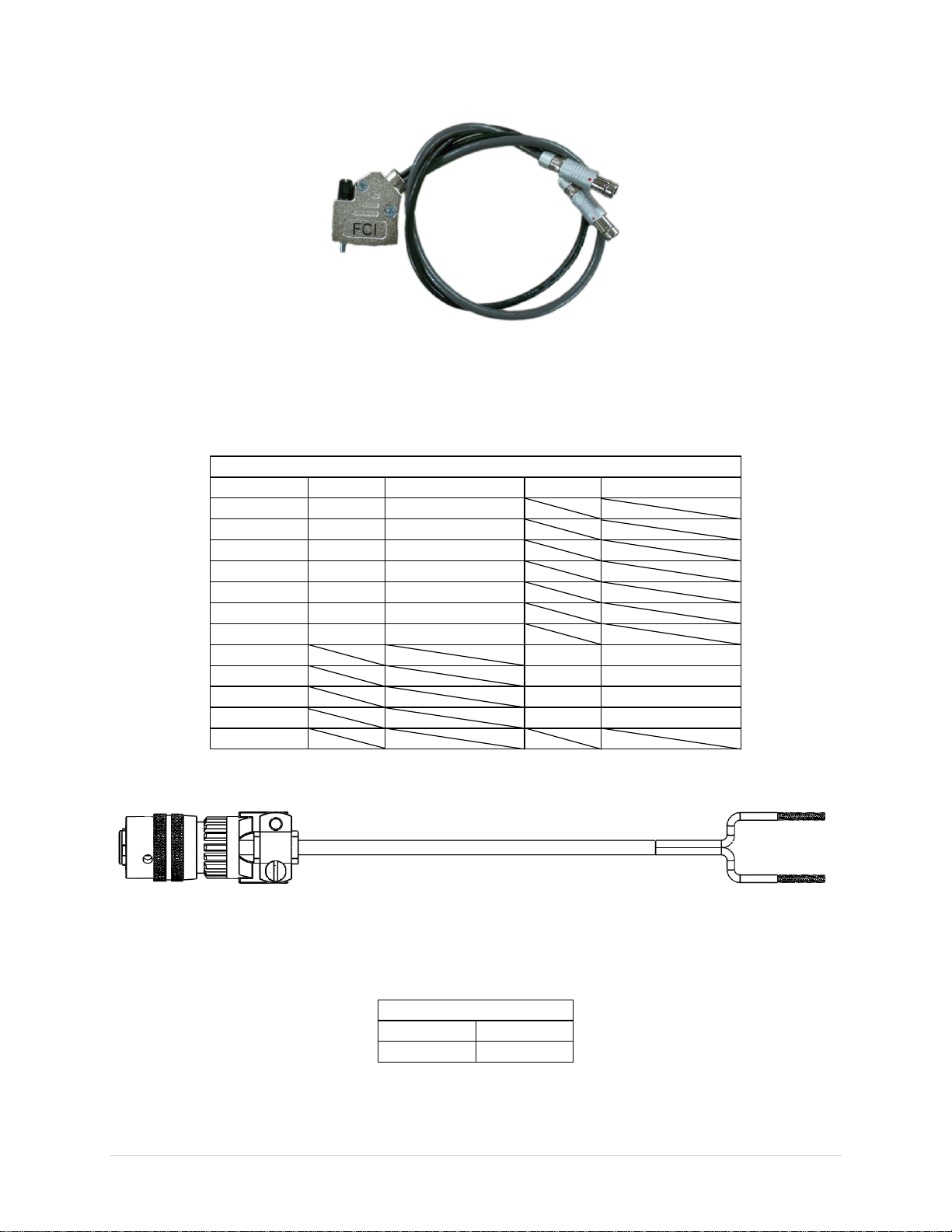
Figure 1-4 AN/PRC-152 KDU/USB Adapter Cable (Optional)
Table 1-5 AN/PRC-152 KDU/USB Adapter Cable Pinout
CONNECTION
73100-00584 73100-00585 (KDU)
1
2 2
173100-00585 (USB)
3 7
4
5 5
6
6 4
12
13 5
7
14 1
15 4
8,9,10,11
7 3
CABLE 4
YELLOW
BLACK
ORANGE
GREEN
BROWN
BLUE
RED
CABLE 5
BLACK
RED
WHITE
GREEN
Figure 1-5 AN/PRC-152 KDU/USB Adapter Cable (1 included)
Table 1-6 Auxiliary Power Output Jacks (5 VDC and 24 VDC) Pinout
CONNECTION
A
BRED
BLACK
6
1.5 Controls, Connectors and Indicators.
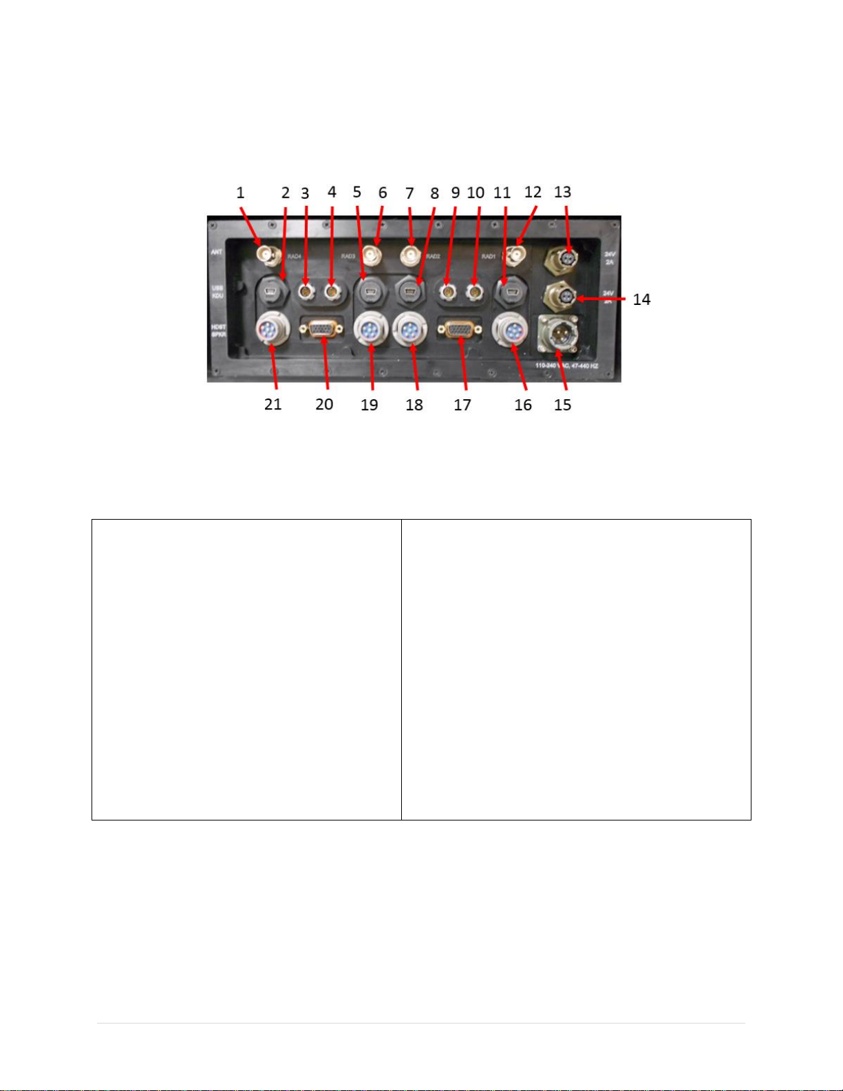
Figure 1-6 TCR-HHR-05 Egress Panel
Table 1-7 TCR-HHR-05 Egress Panel
1
RAD4 Antenna Port
12
RAD1 Antenna Port
2
RAD4 USB Data Interface
13
Auxiliary 24 VDC Output (2A)
3
RAD4 KDU Interface
14
Auxiliary 24 VDC Output (2A)
4
RAD3 KDU Interface
15
AC Power Input Jack
5
RAD3 USB Data Interface
16
RAD1 Handset
6
RAD3 Antenna Port
17
RAD1/RAD2 Speaker Jack
7
RAD2 Antenna Port
18
RAD2 Handset Jack
8
RAD2 USB Data Interface
19
RAD3 Handset Jack
9
RAD2 KDU Interface
20
RAD3/RAD4 Speaker Jack
10
RAD1 KDU Interface
21
RAD4 Handset Jack
11
RAD1 USB Data Interface
7
1
2 3 6
5
4
7
8
9
10
11
12
13
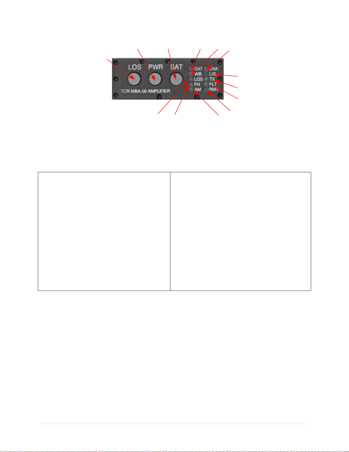
Figure 1-7 TCR-MBA-50 WB Power Amplifier Front Panel
Table 1-8 TCR-HHR-05 Power Amplifier Front Panel
1
LOS Mode Select Button (toggles
between FM, AM, SINCGARS, HAVE
QUICK, WB and WB FH LOS modes)
8
Transmit LED Indicator
2
Power ON/OFF, RF Power Level and
LED Brightness Adjust Button
9
Fault LED Indicator
3
UHF SATCOM Mode Select Button
(toggles between SATCOM LNA OFF
and SATCOM LNA ON modes)
10
Remote LED Indicator
4
SATCOM Mode LED Indicator
11
AM Mode LED Indicator
5
WB Mode LED Indicator
12
Frequency Hopping Mode LED Indicator
6
SATCOM LNA ON Indicator
13
Line of Sight LED Mode Indicator
7
LED Indicator not used
Refer to TCR-MBA-50 WB Operator’s Manual for detail information on the operation of the
Power Amplifier.
8
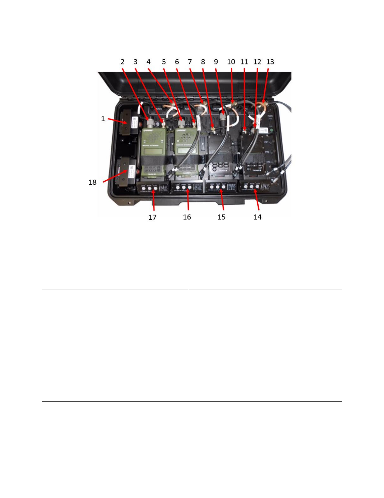
Figure 1-8 TCR-HHR-05 System Components
Table 1-9. TCR-HHR-05 System Components.
1
TCR-SPK-02 Dual Net Amplified Speaker
10
RAD3 Data Cable Adapter (Optional)
2
RAD1 Audio Cable
11
RAD4 RF Cable
3
RAD1 RF Cable
12
RAD4 Audio Cable
4
RAD1 Data Cable Adapter (Optional)
13
RAD4 Data Cable Adapter (Optional)
5
RAD2 Audio Cable
14
RAD4 Radio Mount/PA Control Assembly
6
RAD2 RF Cable
15
RAD3 Radio Mount/PA Control Assembly
7
RAD2 Data Cable Adapter (Optional)
16
RAD2 Radio Mount/PA Control Assembly
8
RAD3 RF Cable
17
RAD1 Radio Mount/PA Control Assembly
9
RAD3 Audio Cable
18
TCR-SPK-02 Dual Net Amplified Speaker
9
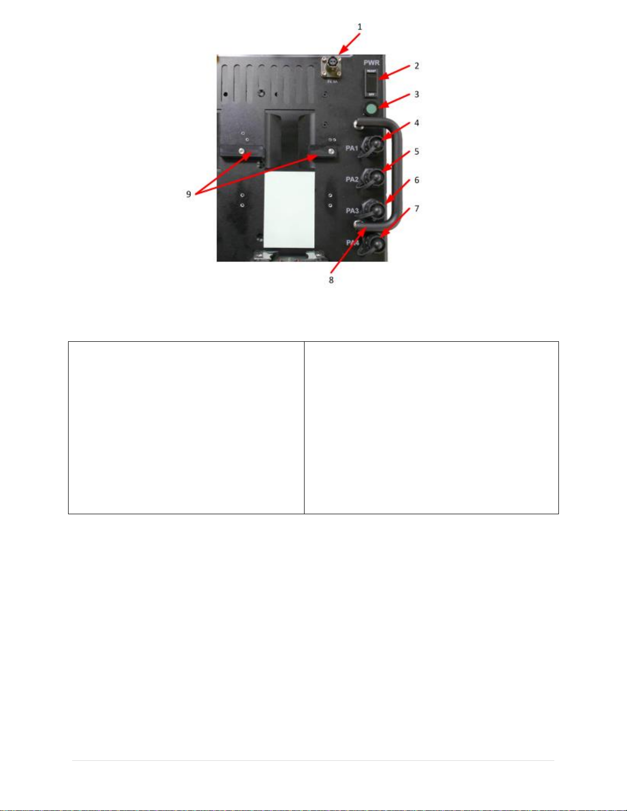
Figure 1-9 TCR-HHR-05 Controls and Indicators
Table 1-10 TCR-HHR-05 Controls and Indicators
1
Auxiliary 5 VDC Output Power (6 A)
6
PA3 USB Interface (used for remote
control)
2
Main Power Switch/Circuit Breaker
7
PA4 USB Interface (used for remote
control)
3
Power ON LED Indicator
8
Handles (used to remove and replace Main
Assembly)
4
PA4 USB Interface (used for remote
control)
9
AN/PRC-148 Radio Spacers (5 places)
5
PA2 USB Interface (used for remote
control)

10
CHAPETR 2
OPERATING INSTRUCTIONS
2. INTRODUCTION.
This chapter will list in chronological order the steps necessary to operate the TCR-HHR-05
safely and efficiently.
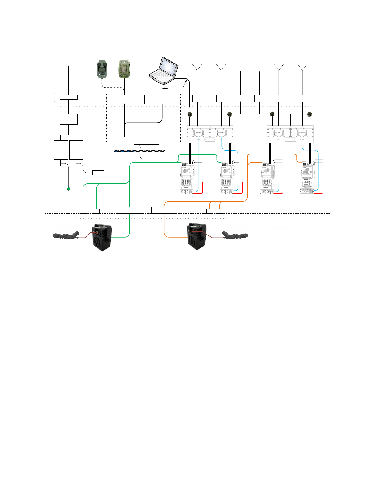
2.1. System Setup. Refer to Figures 2-1 for a system block diagram of the TCR-HHR-05.
2.1.1 Position the AN/PRC-148 radio spacers in the horizontal position for AN/PRC-148
radio applications or in the vertical position for AN/PRC-152 radio applications.
2.1.2 Move the radio/PA control mounts to the vertical position and install radios.
2.1.3 Move the mounted radios down until they rest on the base plate for the AN/PRC-152
radios or on the radio spacers for the AN/PRC-148 radios.
2.1.4 Connect the audio, RF and data cables to each radio.
2.1.5 Secure the radios with the straps provided.
2.1.6 Connect AC power cord to the AC power input jack.
2.1.7 Connect the speaker cables to the speaker ports on the rear egress panel.
2.1.8 Connect the dual net speaker (TCR-SPK-02) to the speaker cables.
2.1.9 Connect the dual net handset to the handset connector on the speakers.
2.1.10 Connect data cables as necessary (only USB and KDU interfaces are provided).
Optional data interface cable adapters are required for data interfaces.
2.1.11 Connect antenna cables to the appropriate antenna port.
2.1.12 If applicable, connect power cable to the self-steering SATCOM antenna to the 24
VDC output jack on the egress panel.
2.1.13 If applicable, connect power cable to Radio Over IP router to the 5 VDC output
jack located on the base plate adjacent to the main power switch.
CAUTION
Lid must remain open during operation for adequate cooling
25 watt mode is recommended for normal SATCOM operation
Ensure antenna attached is rated up to 50 watts
Ensure there is adequate antenna and frequency separation to avoid cosite
interference
For best thermal performance, use PA1/PA3 for nets with the highest duty
cycle and PA2/PA4 for nets with the lowest duty cycle

11
2.2. System Operation. Refer to the radio and power amplifier manuals for setup and
operations instructions of these components.
2.2.1 Turn on the main power switch and verify that the green power indicator is
illuminated.
2.2.2 Turn on power to all radios and power amplifiers.
2.2.3 Select the appropriate net on each radio and ensure that the radio’s power output
setting is at least 2 watts (5 watts recommended).
2.2.4 Select the appropriate mode of operation (SAT, LOS or WB) and power setting on
each power amplifier.
2.3. Power Amplifier Remote Control. Refer to paragraphs 3-6-7 and Appendix A for
instructions on how to control the power amplifier remotely using the USB interface
provided for each PA.
2.4. Radio Over IP (ROIP) Operation. The TCR-HHR-05 provides 5 VDC at 6 Amps
(located on the top panel next to the main power switch) and individual handset jacks
(located on the rear egress panel) to facilitate the interface and operation of the BASICS
ROIP Gateway from Vocality. Refer to the BASICS operator’s manual for setup and
operation of the TCR-HHR-05 for voice over IP.
12
24 VDC #1
BNC
BNC
BNC
BNC
RAD1
ANTENNA
RAD2
ANTENNA
RAD3
ANTENNA
600 WATT
AC-DC
POWER
SUPPLY
90-264 VAC
47-440 HZ
24 VDC #1
24 VDC #2
24 VDC #1 24 VDC #2
RAD1-RAD2
SPEAKER INTERFACE
KDU I/O RADIO USB I/O DATA
RAD1 RAD2 RAD3 RAD4
RAD3-RAD4
SPEAKER INTERFACE
24 VDC #1
24 VDC #2
24 VDC #2
KDU
USB
KDU
USB
KDU
USB
KDU
DATA
4X RADIO
KDU
INTERFACE
4X RADIO
USB DATA
INTERFACE
4X KDU RAD4
ANTENNA
AC POWER IN
10 A
SW/CIRCUIT
BREAKER
600 WATT
AC-DC
POWER
SUPPLY
POWER
INDICATOR
RAD2
HANDSET
RAD1
HANDSET
RAD3
HANDSET
RAD4
HANDSET
DUAL NET HANDSET
ACCUSONIC G06A010-OFK
79000-00503
DUAL NET HANDSET
ACCUSONIC G06A010-OFK
79000-00503
DSUB 15 FEMALE
4X RCU
DSUB 15 MALE KDU
USB
DSUB 15 MALE RCU
USB
OPTIONAL AN/PRC-152
KDU/USB INTERFACE
ADAPTER C ABLE
OPTIONAL AN/PRC-148
RCU/USB INTERFACE
ADAPTER C ABLE
77500-00658
77500-00659
4X USB
EGRESS PANEL (79000-00542)
MAIN ASSEMBLY
STANDARD HARRIS
KDU CABLE (GFE)
OPTIONAL RCU
ADAPTER C ABLE
4X KDU/RCU
USB DATA
INTERFACE
24 VDC
2A
24 VDC
2A
24 VDC #2 24 VDC #2
AUXILIARY POWER
OUTPUT FOR
SELF-STERRING
SATCOM
ANTENN AS
5 VDC
6A
AUXILIARY POWER
FOR BAS ICS ROIP
ROUTER
77500-00615
77500-00615
77500-00614
77500-00649
77500-00649
10000-00633 P1
11000-00771 11000-00771
20000-00121 20000-00121
79000-0054279000-00542
20000-0012320000-00123
20000-00123
20000-00123
77500-00450
PA1
USB RE MOTE
PA2
USB REMOTE
PA3
USB REMOTE
PA4
USB REMOTE
Figure 2-1 TCR-HHR-05 Signal Flow Block Diagram.

13
CHAPTER 3
MAINTENANCE AND WARRANTY INFORMATION
3. INTRODUCTION.
This chapter provides procedures for maintenance of the TCR-HHR-05 Tactical Handheld Radio
Communications Set.
3.1. Preventive Maintenance.
All maintenance procedures are in the subsequent sections.
3.1.1. Dirt and Dust.
All external components to the TCR-HHR-05 can be cleaned with a water dampened
non-abrasive cloth and allowed to air dry or wipe dry with a clean dry non-abrasive cloth.
3.1.2. Oil and Grease.
All external components of the TCR-HHR-05 can be cleaned with a mild soap/water solution
using a non-abrasive cloth. Rinse with water dampened non-abrasive cloth and allowed to air dry
or wipe dry with a clean dry non-abrasive cloth.
3.1.3. Visual Inspections.
Regular inspection of all cables should be performed to ensure that they are free from damage
(i.e., cuts or kinks in outer cable jacket, bent pins, or corrosion). Ensure that the fan assembly
under the case is free from obstructions that there are no signs of damage to the protective
stainless steel mesh.
3.1.4. Self-Test.
Regularly check the TCR-HHR-05 for faults. There is no built in system self-test; however, the
system components can be checked individually to ensure they meet all their specifications.
3.1.5. Power Out Checks.
It is recommended that power out should be checked on the TCR-MBA-50 WB power amplifier
occasionally to prevent any performance degradation to the TCR-HHR-05 Tactical Handheld
Radio Communications Set.
a. Hook up a watt meter in line with the external antenna port under test.
b. Turn the TCR-HHR-05 and watt meter on and place the watt meter in FWD power.
c. Setup the radio for the net under test (RAD1-RAD4) for a minimum of 2 watts (5
watts recommended), FM at 300 MHz and the PA for the appropriate mode under test
(LOS, SAT, WB) key up RAD2 and verify that the watt meter reads the power level
specified in Table 3-1.
e. Turn off and disconnect the watt meter and return the TCR-HHR-05 to normal
configuration.

14
Table 3-1. Power Output Test
MODE
POWER OUTPUT (WATTS)
SAT
10, 15, 25, 35, 50
LOS
25, 50
WB
20
3.2. Corrective Maintenance.
The TCR-HHR-05 has limited user serviceable parts. Table 3-2 contains a list of serviceable
parts that may be obtained from Tricom Research. Units requiring corrective maintenance should
be sent to Tricom Research for repair. Contact information is provided in section 3.4.
Table 3-2. TCR-HHR-05 Equipment Parts List
Equipment
Part Number
Dual Power Amplifier Assembly
20000-00121
PA Remote/Radio Mount Assembly
20000-00123
600 Watt AC Power Supply Assembly
79000-00542
Auxiliary Power Cable
77500-00649
AC Power Input Cable
77500-00614
USB Cable (for PA remote control and radio data)
77500-00450
TCR-SPK-02 Dual Net Amplified Speaker
11000-00771
TCR-SPK-02 Speaker Interface Cable
77500-00615
Dual Net Handset
79000-00503
3.3. Warranty Maintenance.
WARRANTY STATEMENT
Tricom Research warrants to its customers that the products it manufactures and sells will be free
from defects in materials and workmanship for a period of one (1) year.
This warranty shall not apply to any defect, failure, or damage caused by improper use or
inadequate maintenance and care. Tricom Research shall not be obligated to provide service
under this warranty to repair, service, or modify these products.
In order to obtain service under this warranty, customers must return the failed unit to Tricom
Research with a description of the failure, contact information (in case questions arise and to
speed up processing of guarantee claims), and a return shipping address. Tricom Research will
return any failed unit at Tricom Research's cost.
NOTE
THIS WARRANTY DOES NOT APPLY TO ANY EQUIPMENT AND/OR
ACCESSORIES NOT SUPPLIED BY TRICOM RESEARCH AS PART OF
THE TCR-HHR-02 SYSTEM SUCH AS BATTERIES, RADIOS AND ANY
CABLES NOT SUPPLIED WITH THE SYSTEM.
Table of contents
Other TriCom Conference System manuals

Popular Conference System manuals by other brands


AT&T
AT&T MERLIN Plus System manual

Bosch
Bosch CCS 900 Ultro Installation and operating manual

Lenovo
Lenovo ThinkSmart Hub quick start guide

MBTelehealth
MBTelehealth SX10 Quick reference guide

Danish Interpretation Systems
Danish Interpretation Systems DCS 6000 user manual

Siemens
Siemens SWT-3000 Equipment manual