Sonetics SCH310 User manual

SCH310/SCH310T
Wireless DECT7 ComHub
Manual
17600 SW 65th Avenue, Lake Oswego, OR 97035 USA
Phone: 800-833-4558, 503-684-7080, Fax 503-620-2943
www.soneticscorp.com • e-mail: service@soneticscorp.com

Page intentionally left blank

Table of Contents
Overview........................................................................................................................ 1
Contents in Box.............................................................................................................. 1
Accessories (not included)............................................................................................. 2
Features......................................................................................................................... 3
Wireless DECT7 Communications .............................................................................. 3
Waterproof Case........................................................................................................ 3
External Antenna Connectors.................................................................................... 3
Cable Tethering (SCH310T only) ................................................................................ 3
Carry Bag.................................................................................................................... 3
USB Programmable.................................................................................................... 3
Backwards Compatibility ........................................................................................... 4
Wide Band Audio ....................................................................................................... 4
Dual Antenna Design ................................................................................................. 4
Multi-Channel System ............................................................................................... 4
Broadcast Mode ........................................................................................................ 4
Setup.............................................................................................................................. 5
Orientation ................................................................................................................ 5
Height ........................................................................................................................ 5
Line of Sight ............................................................................................................... 6
Charging......................................................................................................................... 7
ComHub Controls .......................................................................................................... 8
Connecting a Portable Radio ......................................................................................... 8
Installing a PR Cable................................................................................................... 8
Adjusting the Gain Controls........................................................................................... 9
Setting Output Gain ................................................................................................. 10
Setting Input Gain .................................................................................................... 10
Pairing Headsets .......................................................................................................... 11
Full-Duplex Pairing................................................................................................... 11
Broadcast Mode Pairing........................................................................................... 11
Example: .................................................................................................................. 11
TETHERING COMHUBS (SCH310T MODEL ONLY) ........................................................ 12
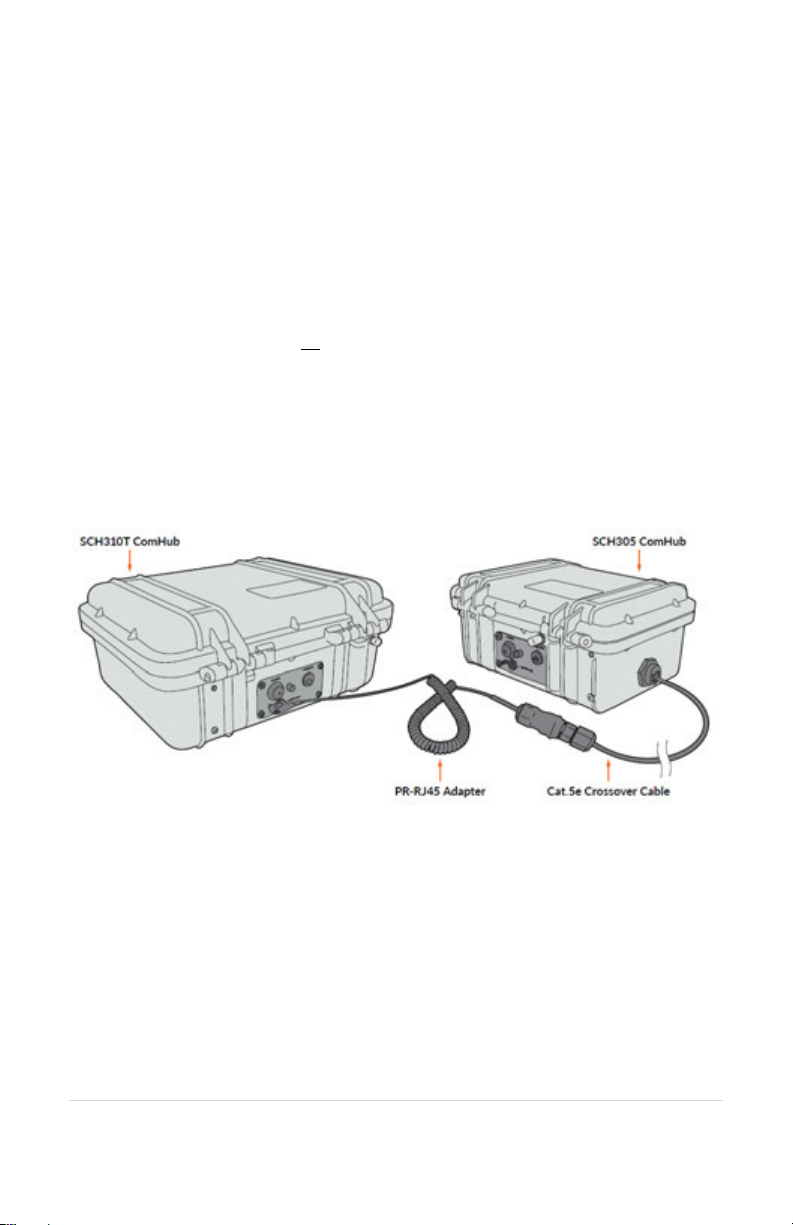
SCH310T to SCH305................................................................................................. 12
SCH310T to SCH310T ............................................................................................... 13
CONNECTING EXTERNAL ANTENNA............................................................................. 14
DECT CHANNEL MODE OPERATION............................................................................. 15
PC Programming .......................................................................................................... 16
Locating the USB Port .............................................................................................. 16
Installation of the Sonetics Configurator Windows Program .................................. 16
Troubleshooting .......................................................................................................... 17
Service Contact: ....................................................................................................... 17
SCH310 (SCH310T) Specifications................................................................................ 18
SON150 Base Station Specifications ............................................................................ 18
DECT Specifications.................................................................................................. 19
Important Safety Information...................................................................................... 21
Sonetics Standard Limited Warranty ........................................................................... 26

Page intentionally left blank

1 | Page
Overview
Sonetics Wireless ComHubs are the heart of a Sonetics Portable Wireless
Communication System. SCH310 ComHubs support full duplex,
conference call-like digital communication for up to 10 Sonetics DECT7
Wireless Headsets. Radio PTT-capable headsets can be configured to
transmit on a portable radio via the ComHub. For situations that require
a large number of connected users, such as education or tour groups,
Broadcast Mode supports up to 100 users. Tethering your SCH310T with
a second ComHub (SCH305 or additional SCH310T) lets you connect two
teams in a single talk group. SCH310/T ComHubs also have DECT channel
capability, allowing users to talk on up to five different channels.
Sonetics DECT7 wireless operates on the 1.9GHz band providing secure,
interference-free, communication. With internal and external antennas,
the ComHub Base Stations configure themselves for best reception and a
line-of-sight range of up to 1,600 feet. USB programming allows complete
customization.
Contents in Box
SCH310 & SCH310T ComHub
Wireless ComHub
2 ea. Duck Antenna
Manual and Reference
SCH310 & SCH310T User Manual
Accessories (included)
SCH310 ComHub Bag
ComHub Bag Hanger Hooks
ComHub Shoulder Strap
12V AC Wall Adapter
12v DC Cigarette Lighter Adapter
SCH310T Model Only
CAT5 Crossover Cable, 7 ft.
PR to RJ45 Jack Adapter

2 | Page
Accessories (not included)
External Antennas
Relocate the line-of-sight point of your ComHub antenna.
Magnetic and permanent mount versions available.
Portable Radio Cables (PR Cables)
Connect to virtually any portable two-way radio and many
other devices. Call us at 877.685.4838 to verify your radio’s
make and model or visit www.soneticscorp.com/radio-
interface-guide/.

3 | Page
Features
Wireless DECT7 Communications
SCH310/T ComHubs feature wireless DECT7, enabling conference call-
like full duplex communication. The ComHub will connect with Sonetics
Wireless Headsets. DECT7 networks have up to 1,600 feet line-of-sight
range in Region 1 (US) and up to 800 meters in Region 2 (EU). DECT7
ensures interference free, digitally encrypted communications for all
parties.
Waterproof Case
Sonetics SCH310 and SCH310T ComHubs are built using genuine
Pelican™ cases for superior waterproofing.
External Antenna Connectors
External antenna connectors provide an option to relocate the wireless
base station antennas when the ComHub must be placed in a location
with poor reception.
Cable Tethering (SCH310T only)
Connect two teams together in a single talk group when you tether your
SCH310T ComHub with an additional SCH310T or an SCH305 ComHub
(requires included PR-RJ45 and CAT5 Crossover cables).
Carry Bag
A rugged nylon carry bag with hi-vis reflective fabric and comfortable
shoulder strap. The included Hanger Hook accessories let you easily and
securely elevate the ComHub for improved range.
USB Programmable
The ComHub’s Base Stations can be configured from integrated USB
ports using a Windows PC. Features may be customized and saved.
Refer to the Sonetics Configuration Utility software for details, or visit
www.soneticscorp.com/support/firmware-update/.

4 | Page
Backwards Compatibility
The ComHub is backward compatible with previous generation Sonetics
Wireless Headsets, with a reduced feature set.
Wide Band Audio
Wireless DECT7 communications are transmitted in a high definition,
wideband audio format for greater voice clarity, and for optional
integration with voice activated control systems. Audio bandwidth can
be switched to narrowband when necessary.
Dual Antenna Design
The ComHub’s Base Stations have internal and external antennas for
improved reception as you move around the work zone.
Multi-Channel System
The ComHub can be configured for use with up to five channels on only
one of its two wireless base stations. These can be remotely selected
from a Wireless Headset paired to the corresponding base station.
Broadcast Mode
Connect up to 3 instructors with up to 100 users for training, education,
tours and other large group applications. Broadcast Mode users must
press PTT to talk with guides or instructors, who remain in Full-Duplex
Mode.
5 | Page
Setup
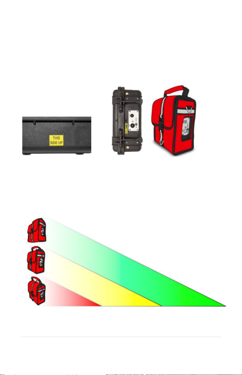
Orientation
The SCH310/T has the greatest range when placed in a specific
orientation. The handle on the bag should be up when in use. Refer to
the orientation stickers on the ComHub and bag for details.
Height
The higher you can safely place the SCH310/T (or its external antennas if
equipped), the better its range. Range can be up to 10 times greater
with the ComHub or antennas 10 feet high than with it on the ground.
Stickers on the sides of the case help you
position the ComHub for
best reception.
10+ feet = Best range
5-10 feet = Typical range
0 feet = Shortest range

6 | Page
Line of Sight
If you can see the ComHub when wearing your DECT7 Headset, you will
experience better reception. When you lose sight of your ComHub, your
reception may be reduced depending on your environment. Walls,
trucks, or other solid objects may degrade reception. Some objects such
as chain link fence may impact reception even though they can be seen
through.
7 | Page
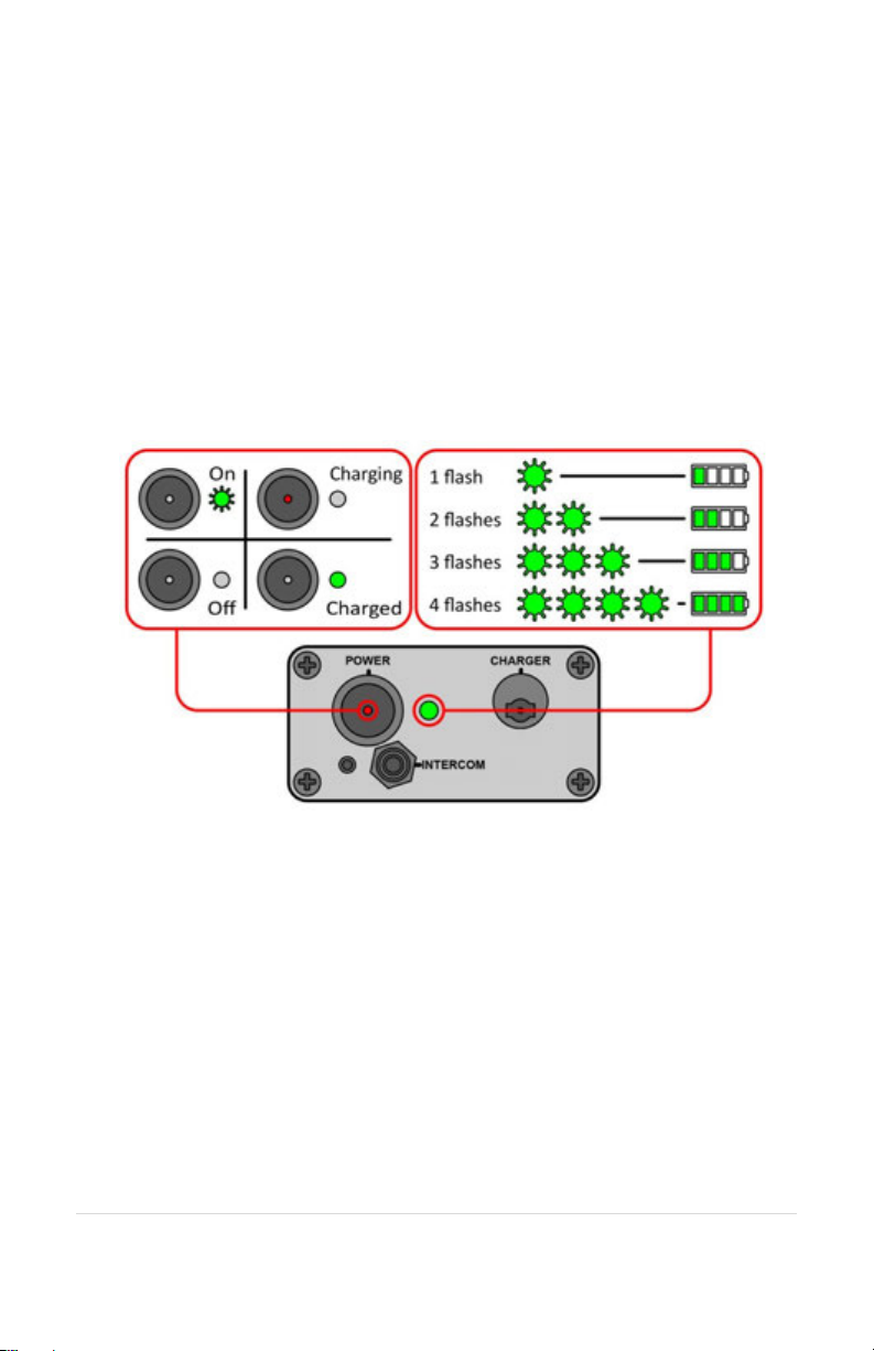
Charging
The SCH310/T charges through a connector on the outside control
panel. There are two LEDs on its control panel to indicate its status.
•Red LED on the Power Button – This lights when the ComHub is
actively charging.
•Green LED next to the Power Button – This lights steady when
the ComHub is fully charged. When the ComHub is turned on,
this LED flashes to indicate the battery charge level. See the
diagram below for details.
8 | Page
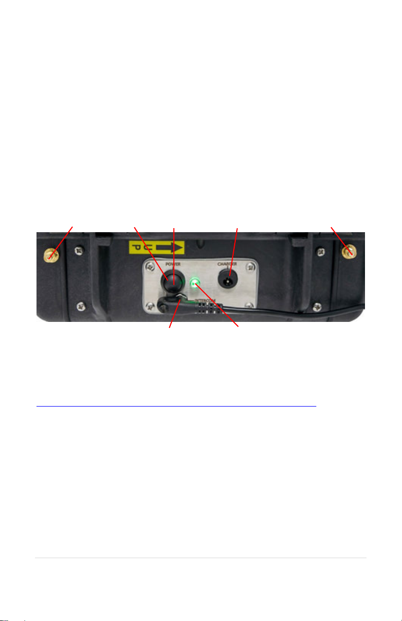
ComHub Controls
•Power Button – Turns the ComHub off and on.
•Charge LED – Indicates when the ComHub is actively charging.
•Status LED – Indicates when the charge cycle is complete. It also
indicates the battery level during use.
•Charge Port – Connects to an external power supply to charge
the ComHub batteries.
•PR Connector – Used to connect a portable radio to the
ComHub.
•External Antenna Ports– Connects accessory external
antennas.
Connecting a Portable Radio
The SCH310/T ComHub can be connected to a variety of handheld
portable radios using Portable Radio (PR) cables. For details, visit
www.soneticscorp.com/accessories/portable-radio-adapters/
NOTE: When two SCH310T ComHubs are tethered, neither ComHub will
allow users to transmit via headset PTT over the portable radio.
Installing a PR Cable
•Once you have selected the correct PR Cable for your
application, attach the end that looks like the image above.
•Use your Sonetics screwdriver to tighten the screw on the
connector to the ComHub. CAUTION: Overtightening can
damage the connector.
•Connect the other end of the PR Cable to your radio.
POWER
BUTTON
POWER
LED
CHARGE
PORT
EXTERNAL
ANTENNA PORT
EXTERNAL
ANTENNA PORT
STATUS LED
INTERCOM PORT

9 | Page
Adjusting the Gain Controls
Input Gain Adjuster
Output Gain Adjuster

10 | Page
Setting Output Gain
1. Set the volume on your radio to between 50 and 75% of
maximum volume.
2. Set the volume on your headset to level it is most commonly
used at.
3. Using a #0 Phillips screwdriver, turn the Output Gain Controller
to its lowest setting (counter-clockwise until it stops).
4. While activating radio transmit and speaking into the headset
mic (get a helper if necessary), VERY slowly turn the Output
Gain Adjuster clockwise until the volume heard on the radio is
at the desired level.
5. DO NOT turn up the Output Gain Controller too quickly.
Adjusting the gains too high will result in poor sound quality,
and could cause your radio to shut down.
Setting Input Gain
1. Set the volume on your radio to between 50 and 75% of
maximum volume.
2. Set the volume on your headset to level it is most commonly
used at.
3. Using a #0 Phillips screwdriver, turn the Input Gain Controller to
its lowest setting (counter-clockwise until it stops).
4. While activating radio transmit and speaking into the radio (get
a helper if necessary), VERY slowly turn the Input Gain Adjuster
clockwise until the volume heard on the headset is at the
desired level.
5. DO NOT turn up the Input Gain Controller too quickly.
Adjusting the gains too high will result in poor sound quality.
11 | Page
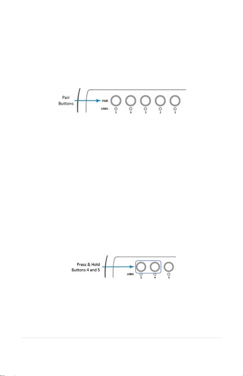
Pairing Headsets
Pairing creates a connection between a ComHub Base Station and the
Headset. This is only required once. After pairing, Headsets will connect
automatically. You may pair any Headset to any position on either Base
Station.
Full-Duplex Pairing
1. Press and hold the desired pairing button until its link indicator begins
to flash slowly. Any previous pairing will be forgotten.
2. With headset powered OFF, place the Headset into pairing mode by
pressing the right PTT button and the power button until you hear
"base station registering".
3. The Base Station will automatically connect, showing a solid link LED.
4. If the pairing was unsuccessful, repeat Steps 1-4 above.
5. Pair any additional Wireless Headsets to remaining open positions.
Broadcast Mode Pairing
Broadcast Mode allows 100 devices to be paired. A full duplex pairing
must be present to activate Broadcast Mode. Broadcast users cannot
Radio Transmit. NOTE: Users may experience a slight loss of range when
utilizing Broadcast Mode.
Example: Position 1 has a Full Duplex Headset pairing. Positions 2-4 are
available for devices to share. Position 5 broadcasts back to the group.
1. Press and hold Buttons 4 & 5 until their link LEDs flash slowly.
2. Place the wireless device you wish to link into pairing mode (see Step
2 above).
3. The Wireless Base Station will automatically connect showing a solid
link LED on Position 5 and the device will show connected (refer to
the Sonetics device manual).
12 | Page
4. If the pairing was unsuccessful, repeat steps 1-3.
5. To pair additional devices, repeat steps 1-4.
Because Broadcast Mode Headsets share communication positions,
there can be slight delays in communication. To talk, the Push-To-Talk
button must be held until a position opens. After a Broadcast call is
made, there will be a pause in which incoming communications cannot
be heard.
To exit Broadcast Mode:
Press and hold Position 4 or Position 5 until the link LED flashes slowly,
indicating pairing mode. Power off the ComHub and power on to
complete the process.
TETHERING COMHUBS (SCH310T MODEL ONLY)
SCH310T to SCH305
Parts needed:
•(1) Cat.5e Crossover Cable*, any length
•(1) PR-RJ45 Adapter
Setup:
1. Attach a PR-RJ45 Adapter to a Cat.5e Crossover Cable using the
instructions included with the PR-RJ45 Adapter.
2. Connect the PR-RJ45 Adapter to the SCH310T ComHub as per
the PR-RJ45 Adapter instructions.

13 | Page
*Please note: the Cat.5e Crossover Cable is a specialized cable. Must
use a "crossover" cable. A standard Cat.5e cable will not work for this
application.
SCH310T to SCH310T
Parts needed:
•(1) Cat.5e Crossover Cable*, any length
•(2) PR-RJ45 Adapter
Setup:
1. Attach the PR-RJ45 Adapters to the Cat.5e Crossover Cable
using the instructions included with the PR-RJ45 Adapter.
2. Connect a PR-RJ45 Adapter to each SCH310T ComHub as per the
PR-RJ45 Adapter instructions.
IMPORTANT NOTES ABOUT TETHERING
A minimum of 7’ of separation between the two ComHubs is
recommended.
When ComHubs are tethered, portable radio push to talk functionality is
altered: For example:
With a SCH310T ComHub tethered to a SCH305 ComHub, a portable
radio can only be interfaced to the SCH305 (not the SCH310T). Users
paired to the SCH305 ComHub can hear and radio push to talk from
their headsets. The users paired to the SCH310T ComHub will be able
to talk in full duplex mode with users from both ComHubs and hear the
portable radio communication, however, they will not be able to push
to talk over the portable radio’s frequency.
When two SCH310T ComHubs are tethered together, the users paired
on either ComHub cannot push to talk to communicate over the
portable radio. Note: each wireless headset paired to either of these
SCH310T ComHubs, needs to set their headset into “DECT Narrow” via
the Advanced Menu on the headset.

14 | Page
CONNECTING EXTERNAL ANTENNA
Follow these steps to connect the accessory external antennas (not
included). IMPORTANT: To avoid performance degradation, two
external antennas must be used simultaneously:
1) Remove the ComHub from the red carry bag.
2) Open the lid by releasing the two underside latches.
3) Remove the faceplate around the base stations by gently pulling
on each corner (Fig. 1).
4) Disconnect the Duck Antennas from the Base Stations (located
inside the lid of the ComHub). Place the Duck Antennas in the
carry bag’s side pouch for safekeeping.
5) Attach the gold coaxial connectors to the antenna ports on the
base stations (Fig. 2).
6) Remove the black plastic covers at either end of the control
panel, exposing the external coaxial connectors.
7) Connect the external antennas’ coaxial cables to the gold
connectors (Fig. 3).
Fig. 1 (left): Faceplate removed.
Fig. 2 (above): Internal coaxial connections.
Fig. 3 (below): External coaxial connections.

15 | Page
DECT CHANNEL MODE OPERATION
When used in this configuration, up to 5 channels are available from
only one of the ComHub’s two Base Stations.
Configuring for Channel Selection (ComHub Mode)
To enter configuration mode; select a Base Station on which to enable
DECT channels. NOTE: Either Base Station will work for this purpose. In
order to use DECT channels, Wireless Headset users must be paired to
the Base Station with DECT channels enabled.
1. Power off the ComHub.
2. While holding the Position 3 pairing button, power on the
ComHub.
3. Continue holding the Position 3 pairing button for 10 seconds.
4. The Base Station is now ready to select the number of DECT
channels.
Selecting the Number of Available Channels
5. Press the pair button corresponding to the number of channels
desired (button 2 = 2 channels, etc.).
6. To exit configuration mode, power off the ComHub and then
power it on.
Headset Verification of Available DECT Channels
Before you begin using channels, verify that you have the expected
number of available DECT channels by cycling through channels using
the Wireless Headset:
1. Turn on your APX377 or APX379 Wireless Headset.
2. Allow the Headset to pair with the ComHub or Base Station.
3. Press the forward and back buttons together to toggle
DECT Channel Selection. A voice prompt announces “Channel”.
4. Press the forward or back button on the right-hand side of
the Headset. Voice prompts announce “Channel 1”, “Channel
2”, and so on.
5. If you are unable to access the expected number of DECT
channels, repeat Steps 1-6 in “Configuring and Selecting…”
above.

16 | Page
PC Programming
The Wireless Base Station in your ComHub has a USB port located near
the Antenna Jack. Using the Sonetics Configurator program, you can
adjust additional features using a Windows PC, or perform firmware
updates when necessary. Refer to the program for additional
information.
Locating the USB Port
Installation of the Sonetics Configurator Windows
Program
1. Go to www.SoneticsCorp.com/software.
2. Download and Install the program for the wireless base station.
3. Plug in the USB cable from the Wireless Base Station to the computer.
The Base Station will power up.
4. Open the Sonetics program.
5. Follow the directions of the Sonetics program.
(Left) The USB port is located in the center of the
side wall of the base station, just below the
Sonetics logo.
(Below) To access the USB port, remove the tray
from the case by lifting up at the edges to
release the hook-and-loop fasteners.
This manual suits for next models
1
Table of contents
Other Sonetics Conference System manuals


