Trident Emergency Products, LLC
2940 Turnpike Drive | Suite #9 | Hatboro, PA 19040 USA
2
AirPrime™ Fire Pump Priming System
™
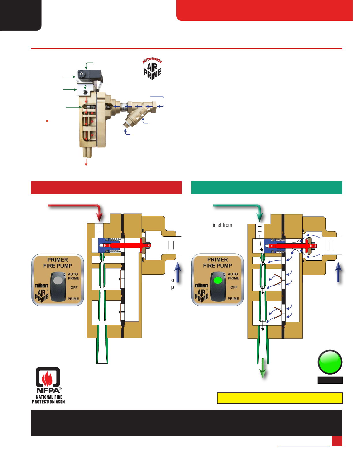
AirPrime™ Overview
Trident has several AirPrime models to meet specic needs:
Base Models: All models are available in 2 or 3 barrel design
(depending on your water pump capacity and chassis air
compressor output CFM).
Direct Mount: Connects to a Hale Q Model midship pump
priming port with two bolts. The Hale pump model name must begin
with a Qsuch as Qmax. Hale supplies a lter for the Direct Mount.
Remote Mount: This version can be used with any pump. It has
a 3⁄4" female NPT connection and requires a simple bracket to hold
the unit to the pump house structure.
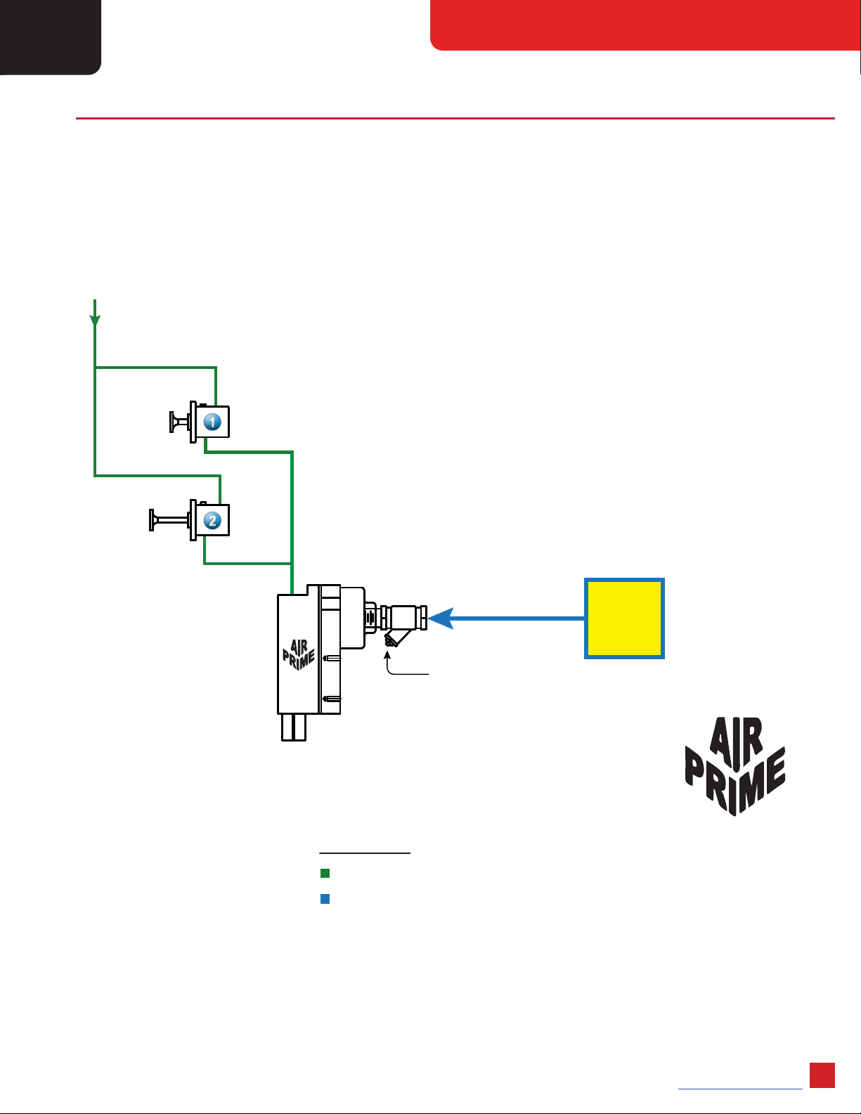
Multi-Location: Priming from multiple inlet locations.
Variations and Options:
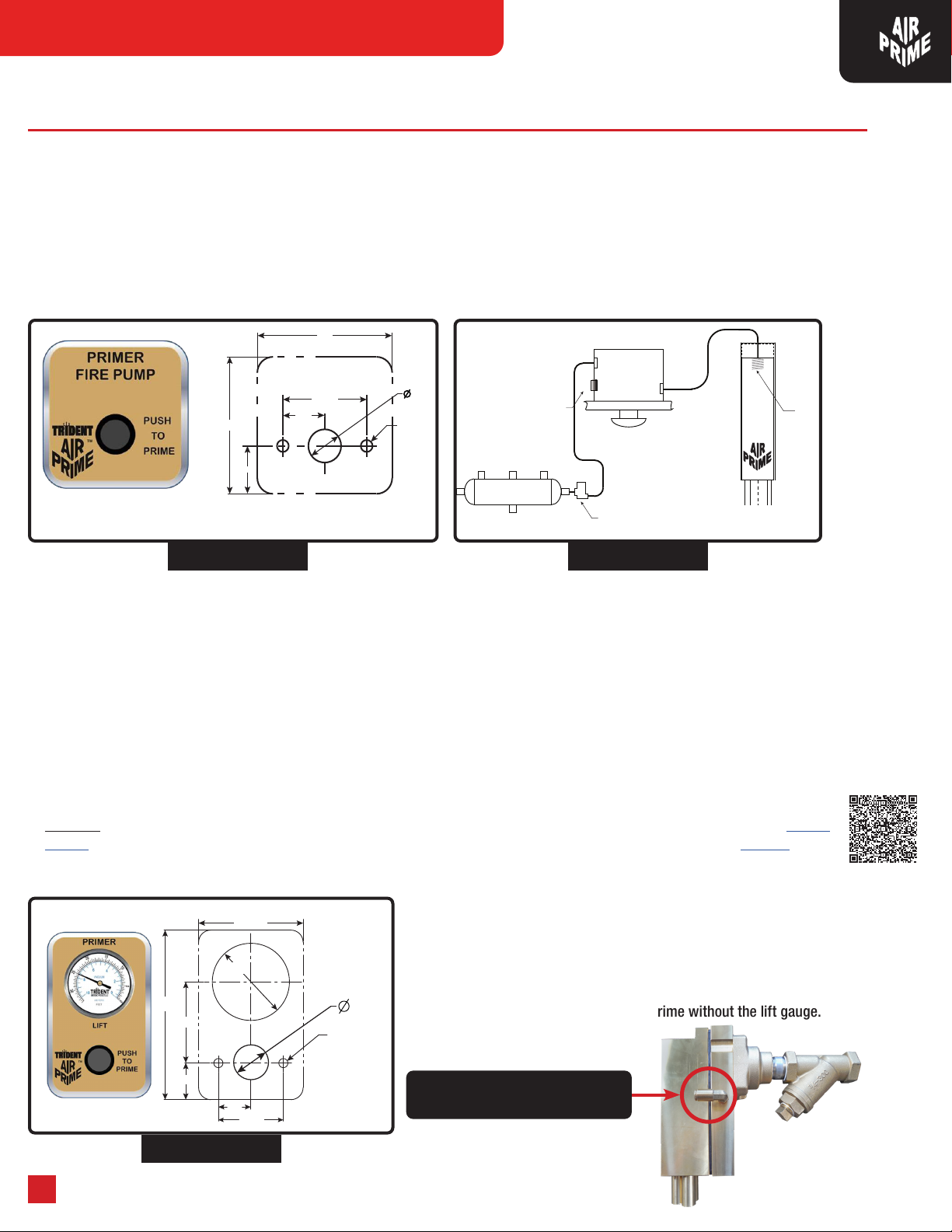
1. The base AirPrime single location units are available with either
Automatic or Manual controls.
2. The Multi-Location units are available with Automatic or Manual
controls. Up to four remote locations are available. This allows for
pre-priming up to the buttery valve for rapid water delivery and safer
reground operations.
3. Automatic versions are available in 12 and 24 Volt models.
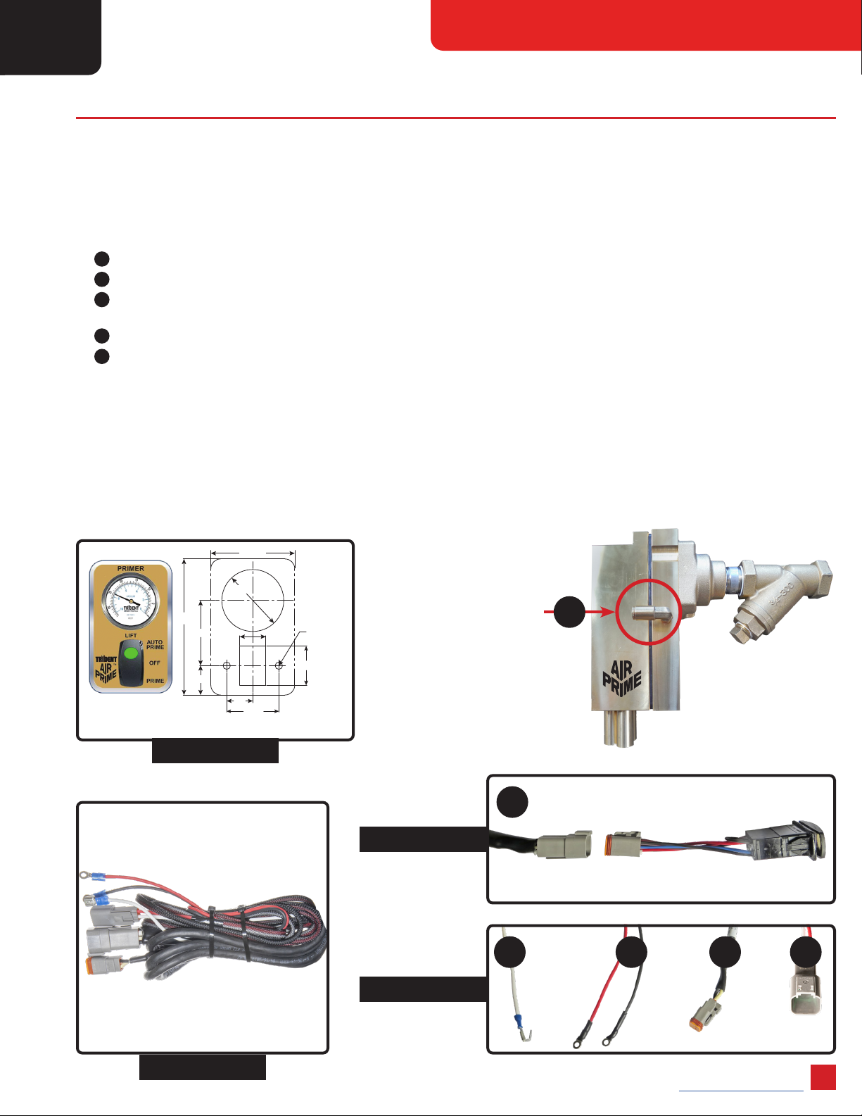
4. Adding a Lift Gauge which indicates how much vacuum (in feet/meters
of water) the primer is creating to prime the pump.
5. Conversion Kits for Manual to Automatic and for adding more locations
are available. Refer to Page 16.
6. AirPrime is also available for small trucks without air brakes.
See Page 5 for additional information.
7. Industrial AirPrime units are available for large re pumps.
Contents
Available Models������������������������������������������������������������������������������������������������������������������������������������������������������������������������������������������������������������������������������2
AirPrime™ Overview�����������������������������������������������������������������������������������������������������������������������������������������������������������������������������������������������������������������������2
AirPrime™- How Does It Work��������������������������������������������������������������������������������������������������������������������������������������������������������������������������������������������������������3
Installer Responsibilities ������������������������������������������������������������������������������������������������������������������������������������������������������������������������������������������������������������������4
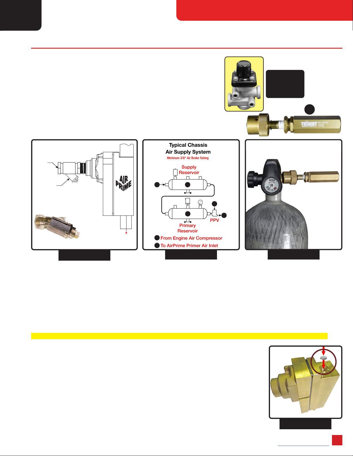
Air Schematic, PPV, Air Hose and Connections����������������������������������������������������������������������������������������������������������������������������������������������������������������������������������5
Automatic Single Location AirPrime™System���������������������������������������������������������������������������������������������������������������������������������������������������������������������������������6
Automatic Single Location AirPrime™ System with Optional Vacuum Gauge������������������������������������������������������������������������������������������������������������������������������������7
Automatic Primer Switch Wiring Details �������������������������������������������������������������������������������������������������������������������������������������������������������������������������������������������8
Optional In Cab Primer Control ���������������������������������������������������������������������������������������������������������������������������������������������������������������������������������������������������������9
Manual Single Location AirPrime™Systems ���������������������������������������������������������������������������������������������������������������������������������������������������������������������������������10
Multi Location Installation and Operating Instructions���������������������������������������������������������������������������������������������������������������������������������������������������������������������11
Multi Location Automatic AirPrime™System Diagram�������������������������������������������������������������������������������������������������������������������������������������������������������������������12
Multi Location Manual AirPrime™System Diagram�����������������������������������������������������������������������������������������������������������������������������������������������������������������������13
Trouble Shooting Guide������������������������������������������������������������������������������������������������������������������������������������������������������������������������������������������������������������������14
Trouble Shooting Guide (Continued) �����������������������������������������������������������������������������������������������������������������������������������������������������������������������������������������������15
AirPrime™Industrial and SC Systems �������������������������������������������������������������������������������������������������������������������������������������������������������������������������������������������15
Annual Primer Testing ��������������������������������������������������������������������������������������������������������������������������������������������������������������������������������������������������������������������16
Warranty and Product Information��������������������������������������������������������������������������������������������������������������������������������������������������������������������������������������������������17
Installation/Operation Notes �����������������������������������������������������������������������������������������������������������������������������������������������������������������������������������������������������������18
Installation/Operation Notes �����������������������������������������������������������������������������������������������������������������������������������������������������������������������������������������������������������19
Repair/Replacement Parts��������������������������������������������������������������������������������������������������������������������������������������������������������������������������������������������������������������20
Available Models
Automatic Control
Auto Base Model
Auto Base Model w/ Lift Gauge
Auto Multi Location
Auto Multi Location w/ Lift Gauge
Industrial Pumper Units
Manual Control
Manual Base Model
Manual Base Model with Lift Gauge
Manual Multi Location
Manual Multi Location w/ Lift Gauge
AirPrime SC 1906 Wildland Unit
100' of Suction Hose Deployed100' of Suction Hose Deployed
For more information on all available models please visit:
TridentDirect.com or TridentAutoAirPrime.com
Replacing a Rotary Vane Primer?
View our AirPrime Retrot and Upgrade Guide
Please Visit the Trident YouTube Channel
Closed Buttery Valve
Pre-Priming Example