Tridonic Essence LC 35W 200-350mA stepDIM lp SNC User manual

www.tridonic.com 1
Subject to change without notice. Information provided without guarantee.
Data sheet 11/21-LC888-6
LED Driver
Linear fixed output
Product description
• Constant current built-in LED Driver
• Motion and daylight detection (included in delivery)
• For luminaires of protection class I and protection class II
• Temperature protection as per EN 61347-2-13 C5e
• Selectable fixed output current 350, 300, 250 and 200 mA
• Max. output power 35 W
• Up to 87 % eiciency
• Nominal life-time up to 100,000 h
• 5-year guarantee (conditions at www.tridonic.com)
Housing properties
• Casing Driver: metal, white
• Casing sensor: polycarbonat, white
• Type of protection IP20
Functions
• Overload protection
• Short-circuit protection
• No-load protection
È
Technical data LED Driver, page 3
Product description LED Driver, page 4–6
Technical data Motion Sensor, page 3
Product description Motion Sensor, page 7–9
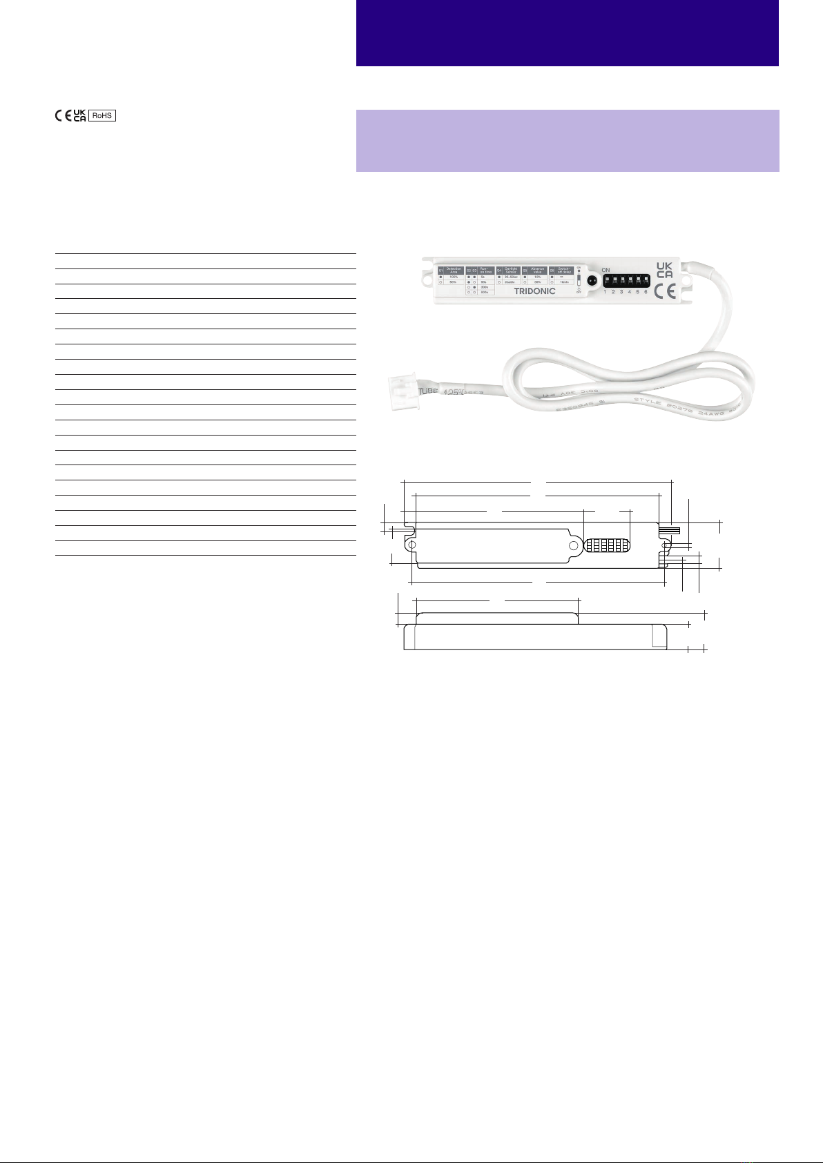
Driver LC 35W 200-350mA stepDIM lp SNC
essence series non-SELV (stepDIM)
LED Driver with sensor (included in delivery)

www.tridonic.com 2
Subject to change without notice. Information provided without guarantee.
Data sheet 11/21-LC888-6
LED Driver
Linear fixed output
Technical data
Rated supply voltage 220 – 240 V
AC voltage range 198 – 264 V
Input current (at 230 V, 50 Hz, full load) 0.185 A
Leakage current (at 230 V, 50 Hz, full load) < 450 µA
Mains frequency 50 / 60 Hz
Overvoltage protection 320 V AC, 1 h
Output power range 10.4 – 36.4 W
Typ. eiciency (at 230 V / 50 Hz / full load)287 %
λ (at 230 V, 50 Hz, full load)20.95
Output current tolerance3± 7.5 %
Max. output voltage 320 V
THD (at 230 V, 50 Hz, full load)2< 10 %
Max. peak output current at full load2390 mA
Output LF current ripple (< 120 Hz) at full load ± 3 %
Output PstLM (at full load) ≤ 1
Output SVM (at full load) ≤ 0.4
Starting time (at 230 V, 50 Hz, full load) ≤ 0.5 s
Turn o time (at 230 V, 50 Hz, full load) ≤ 0.5 s
Hold on time at power failure (output) 0 s
Ambient temperature ta (at life-time 50,000 h) 60 °C
Storage temperature ts -40 ... +80 °C
Mains burst capability 1 kV
Mains surge capability (between L – N) 1 kV
Mains surge capability (between L/N – PE) 2 kV
Surge voltage at output side (against PE) 4 kV
Life-time up to 100,000 h
Guarantee (conditions at www.tridonic.com) 5 years
Dimensions L x W x H 230 x 30 x 21 mm
Hole spacing D 218 mm
Driver LC 35W 200-350mA stepDIM lp SNC
essence series non-SELV (stepDIM)
230
21
122.4
tc
4
30
218
ø4.1
tc
16.2
side fixing feature
Ordering data
Type1Article
number
Packaging,
carton
Packaging,
pallet
Weight
per pc.
LC 35/200-350/121 stepDIM lp SNC 20 pc(s). 420 pc(s). 0.158 kg
Specific technical data
Type Output
current4
Min. forward
voltage
Max. forward
voltage
Max. output
power
Typ. power consumption
(at 230 V, 50 Hz, full load)
Typ. current consumption
(at 230 V, 50 Hz, full load)
Max. casing
temperature tc
Ambient
temperature
ta max.
Iout select
LC 35/200-350/121 stepDIM lp SNC
200 mA 52 V 121 V 24.2 W 27. 5 W 130 mA 80 °C -20 ... +60 °C 1=off / 2=off
250 mA 52 V 121 V 30.3 W 33.3 W 155 mA 80 °C -20 ... +60 °C 1=off / 2=on
300 mA 52 V 121 V 36.3 W 40.5 W 185 mA 80 °C -20 ... +60 °C 1=on / 2=off
350 mA 52 V 104 V 36.4 W 41.0 W 185 mA 80 °C -20 ... +60 °C 1=on / 2=on
1LED Driver with sensor (included in delivery).
2Test result at 350 mA.
3Test result at 25 °C.
4Output current is mean value.
Motion Sensor (included)
Automatic switching based on motion and light level
123456
ON DIP
81
59
55
84
89
15.8
ø1.7
8.5
12.1
11
3.6
15.5
2.7
2.7
2.8
www.tridonic.com 3
Subject to change without notice. Information provided without guarantee.
Data sheet 11/21-LC888-6
LED Driver
Linear fixed output
Technical data
Supply voltage DC 5.3 – 10 V
Current draw 45 mA
Max. input current 50 mA
Output signal 0 – 5 V (PWM 3 kHz)
Power < 0.5 W
Frequency 5.8 GHz ( 75 MHz)
Transmission power < 0.2 mW
Detection angle 150°
Max. detection area1ø 14 m
Max. mounting height 6 m
tc 70 °C
Ambient temperature ta -20 ... +70 °C
Storage temperature ts -20 ... +70 °C
Humidity min. 5 % ... max. 95 %
Type of protection IP20
Protection class Protection class II
Casing material PC, halogen-free
Casing colour White
Dimensions L x W x H 89 x 15.8 x 12.1 mm
Hole spacing D 84 mm
Motion Sensor (included)
Automatic switching based on motion and light level
123456
ON DIP
81
59
55
84
89
15.8
ø1.7
8.5
12.1
11
3.6
15.5
2.7
2.7
2.8
1≥ 3.5 m radius at 1 m/s speed at mounting height 3 m.
www.tridonic.com 4
Subject to change without notice. Information provided without guarantee.
Data sheet 11/21-LC888-6
LED Driver
Linear fixed output
1. Standards
EN 55015
EN 61000-3-2
EN 61000-3-3
EN 61347-1
EN 61347-2-13
EN 61547
EN 62384
EN 60598-1
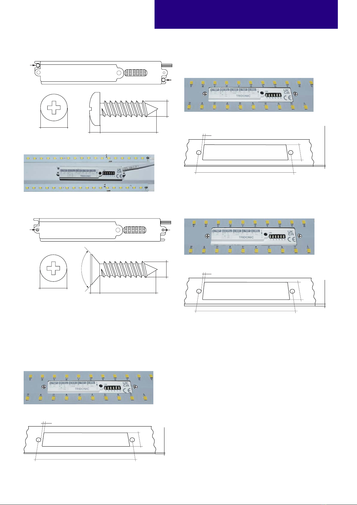
3.7 Mounting of device
Max. torque for fixing: 0.5 Nm/M4
The LED Driver is designed for a life-time stated above under reference
conditions and with a failure probability of less than 10 %.
2. Thermal details and life-time
2.1 Expected life-time
3. Installation / wiring
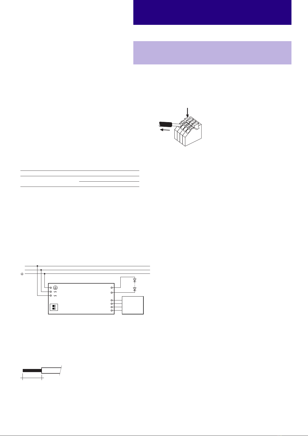
3.1 Circuit diagram
3.2 Wiring type and cross section
The wiring can be stranded wires with ferrules or rigid wires with a cross
section of 0.5 – 1.5 mm².
Strip 8.5 – 9.5 mm of insulation from the cables to ensure perfect operation
of the push-wire terminals (WAGO 250).
– mm
wire preparation:
– mm²
3.3 Release of the wiring
Press down the “push button” and remove the cable from front.
3.4 Wiring guidelines
• All connections must be kept as short as possible to ensure good EMI
behaviour.
• Mains leads should be kept apart from LED Driver and other leads
(ideally 5 – 10 cm distance)
• Max. length of output wires is 2 m.
• Incorrect wiring can damage LED modules.
• To avoid the damage of the Driver, the wiring must be protected against
short circuits to earth (sharp edged metal parts, metal cable clips, louver,
etc.).
3.5 Earth connection
The earth connection is conducted as protection earth (PE). The LED Driver
can be earthed via metal housing. If the LED Driver will be earthed,
protection earth (PE) has to be used. There is no earth connection required
for the functionality of the LED Driver. Earth connection is recommended to
improve following behaviour.
• Electromagnetic interferences (EMI)
• Transmission of mains transients to the LED output
In general it is recommended to earth the LED Driver if the LED module is
mounted on earthed luminaire parts respectively heat sinks and thereby
representing a high capacity against earth.
For Class II application, protection earth is no need to be connected, below 2
scenarios should be considered:
• If the LED Driver housing is screw on a metal part inside the luminaires,
both LED Driver and LED module must be insulated.
• If the LED Driver housing is screw on a plastic part inside the luminaires,
the LED module need to be insulated.
3.6 Replace LED module
1. Mains off
2. Remove LED module
3. Wait for 30 seconds
4. Connect LED module again
Hot plug-in or output switching of LEDs is not permitted and may cause
a very high current to the LEDs.
SEC
PRI
220–240 V
L
50/60 Hz
+ LED
3.3Vaux
GND
5Vaux
PWM
– LED
N
ON
I-select
LC stepDIM lp SNC
Motion
Sensor
Type ta 50 °C 60 °C
LC 35/200-350/121 stepDIM lp SNC tc 70 °C 80 °C
Life-time 100,000 h 50,000 h
Driver LC 35W 200-350mA stepDIM lp SNC4
Product description
The relation of tc to ta temperature depends also on the luminaire design.
If the measured tc temperature is approx. 5 K below tc max., ta temperature
should be checked and eventually critical
components (e.g. ELCAP) measured. Detailed information on request.
www.tridonic.com 5
Subject to change without notice. Information provided without guarantee.
Data sheet 11/21-LC888-6
LED Driver
Linear fixed output
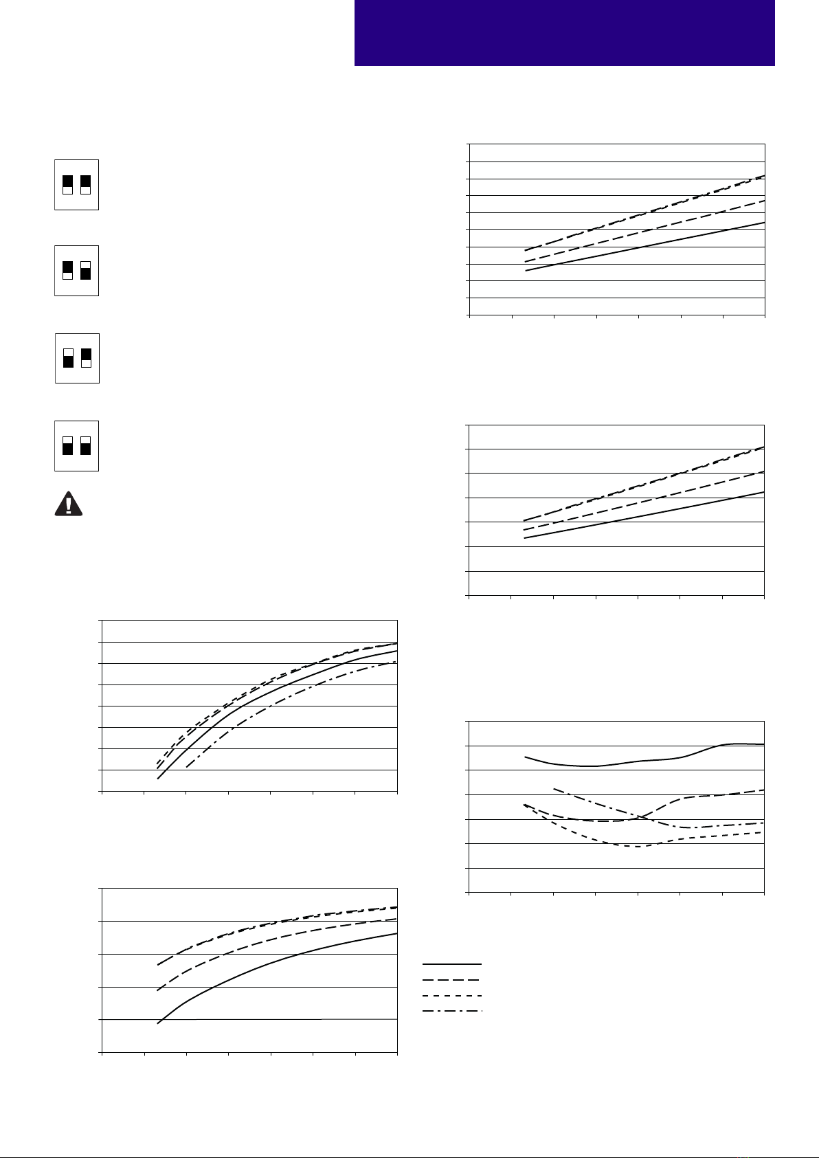
4.5 THD vs load (without harmonic < 5 mA or 0.6 % of the input current)
4.1 Efficiency vs load
4.2 Power factor vs load
4.3 Input power vs load
4.4 Input current vs load
4. Electrical values
THD without harmonic < 5 mA (0.6 %) of the input current:
0
14
30 80 9060 7040 50
100
12
10
2
4
6
8
Load [%]
THD [%]
82
85
86
84
83
87
88
89
90
30 50 7060 80 9040
100
Load [%]
Eiciency [%]
0,75
0,80
0,90
0,85
0,95
1,00
30 60
50 70 80 9040
100
Load [%]
Power factor
0
50
8070 90605030 40
100
5
15
10
25
20
40
45
35
30
Load [%]
Input power [W]
0
210
8070 906030 40 50
100
180
150
120
90
60
30
Load [%]
Input current [mA]
3.8 Current setting
200 mA: Switch 1 = Off, Switch 2 = Off
350 mA: Switch 1 = On, Switch 2 = On
250 mA: Switch 1 = Off, Switch 2 = On
1 2
ON
1 2
ON
1 2
ON
1 2
ON
300 mA: Switch 1 = On, Switch 2 = Off
200 mA
300 mA
250 mA
350 mA
Set the current by DIP switch after mains off.
Use of DIP switch only after mains off.

www.tridonic.com 6
Subject to change without notice. Information provided without guarantee.
Data sheet 11/21-LC888-6
LED Driver
Linear fixed output
6.1 Insulation and electric strength testing of luminaires
Electronic devices can be damaged by high voltage. This has to be considered
during the routine testing of the luminaires in production.
According to IEC 60598-1 Annex Q (informative only!) or ENEC 303-Annex A,
each luminaire should be submitted to an insulation test with 500V DC for
1 second. This test voltage should be connected between the interconnected
phase and neutral terminals and the earth terminal.
The insulation resistance must be at least 2 MΩ.
As an alternative, IEC 60598-1 Annex Q describes a test of the electrical
strength with 1500 V AC (or 1.414 x 1500 V DC). To avoid damage to the electronic
devices this test must not be conducted.
6.3 Additional information
Additional technical information at www.tridonic.com →Technical Data
Life-time declarations are informative and represent no warranty claim.
No warranty if device was opened.
6.2 Conditions of use and storage
Humidity: 5 % up to max. 85 %,
not condensed
(max. 56 days/year at 85 %)
Storage temperature: -40 °C up to max. +80 °C
The devices have to be within the specified temperature range (ta) before
they can be operated.
The LED Driver is declared as inbuilt LED controlgear, meaning it is intended
to be used within a luminaire enclosure.
If the product is used outside a luminaire, the installation must provide
suitable protection for people and environment (e.g. in illuminated ceilings).
Automatic circuit
breaker type
C10 C13 C16 C20 B10 B13 B16 B20 Inrush current
Installation Ø1.5 mm21.5 mm21.5 mm22.5 mm21.5 mm21.5 mm21.5 mm22.5 mm2Imax Time
LC 35/200-350/121 stepDIM lp SNC 36 47 58 73 36 47 58 73 12 A 80 µs
THD 3. 5. 7. 9. 11.
LC 35/200-350/121 stepDIM lp SNC < 10 < 7 < 5 < 5 < 5 < 3
Acc. to 6100-3-2. Harmonics < 5 mA or < 0.6 % (whatever is greater) of the input current are
not considered for calculation of THD.
4.7 Harmonic distortion in the mains supply (at 230 V / 50 Hz and full load)
in %
5. Functions 6. Miscellaneous
5.1 Short-circuit behaviour
In case of a short circuit on the output side (LED) the LED Driver switches off.
After elimination of the short-circuit fault the LED Driver will recover
automatically.
5.2 No-load operation
The LED Driver works in burst working mode to provide a constant output
voltage regulation which allows the application to be able to work safely when
LED string opens due to a failure.
4.6 Maximum loading of automatic circuit breakers in relation to inrush current
These are max. values calculated out of continuous current running the device on full load. There is no limitation due to in-rush current.
If load is smaller than full load for calculation only continuous current has to be considered.
Motion Sensor
Product description
5.3 Overload protection
If the maximum load is exceeded by a defined internal limit, the LED Driver
will protect itself and LED may flicker. After elimination of the overload, the
nominal operation is restored automatically.

www.tridonic.com 7
Subject to change without notice. Information provided without guarantee.
Data sheet 11/21-LC888-6
LED Driver
Linear fixed output
Motion Sensor
Product description
1.1 Glow wire test
according to EN 60598-1 with increased temperature of 850 °C passed.
1. Standards
IEC 61347-1
IEC 61347-2-11
EN 61347-1
EN 61347-2-11
2. Description
• The schell is made of flame retardant, with fire rating of V-0
• Compared with PIR module, microwave motion sensor is better – more
wide detection range, no dead area, no fresnel lens, no aging problem,
no environment interface
• Strong anti-interference ability – it is not affected by temperature,
humidity, airflow, dust, noise, brightness and other factors.
• Avoid installing metal accessories or shells, metal will block
the microwave and affect the effect.
• The antenna surface should avoid large current circuit coverage,
which may cause interference.
• The photosensitive position should avoid being blocked by
opaque objects, which will change the light intensity.
• The recommended installation distance of the sensor is
greater than 1.5 m.
3. Installation
3.1 Circuit diagram
123456
ON DIP
white tighted
heat tube white tighted
heat tube
490
±5
10 ±3
20 ±3 23 ±5
1
3
4
2
1 ... Blank
2 ... Black
3 ... Re
d
4 ... Y
ellow
Cable: White UL 20276 3x24AWG black-red-yellow
Heat tube: φ4.5 UL L = 28 mm
Connector: XH2.5-T 4P white shell with buckle
www.tridonic.com 8
Subject to change without notice. Information provided without guarantee.
Data sheet 11/21-LC888-6
LED Driver
Linear fixed output
3.2 Ceiling installation
3.3 Embedded installation
123456
ON DIP
M3
M3
Tolerance: ± 0.2 mm
5.3
1.9 6
3
123456
ON DIP
M2
M2
Tolerance: ± 0.2 mm
3.7
1.21 8
2
90°
M2
>13
84
M2
1
D < 1 mm
M2
>15
84
M2
1
1 mm < D < 2 mm
M2 >18
84
M2
1
D > 2 mm
When the radar module is embedded in the lamp board or aluminum sub-
strate, the metal is close to the RF hollow width of the lamp board or alu-
minum substrate is required as follows:
1. When the thickness of the baffle plate and the aluminum
substrate (all the metal part) is D < 1 mm, the suggested hollow length is
80 mm, width > 13 mm.
2. When the thickness of the baffle plate and the aluminum substrate
(all the metal part) is 1 mm < D < 2 mm, the suggested hollow length is
80 mm, width > 15 mm.
3. When the thickness of the lamp block plate and the aluminum substrate
(all the metal part )is D > 2 mm, the suggested hollow length is 80 mm,
width > 18 mm.
lamp board:
aluminum substrate:
lamp board:
aluminum substrate:
lamp board:
aluminum substrate:
www.tridonic.com 9
Subject to change without notice. Information provided without guarantee.
Data sheet 11/21-LC888-6
LED Driver
Linear fixed output
Setting the daylight sensor (4. code switch)
Setting the standby dimming (5. code switch)
Setting the second-order delay (6. code switch)
4. Functions
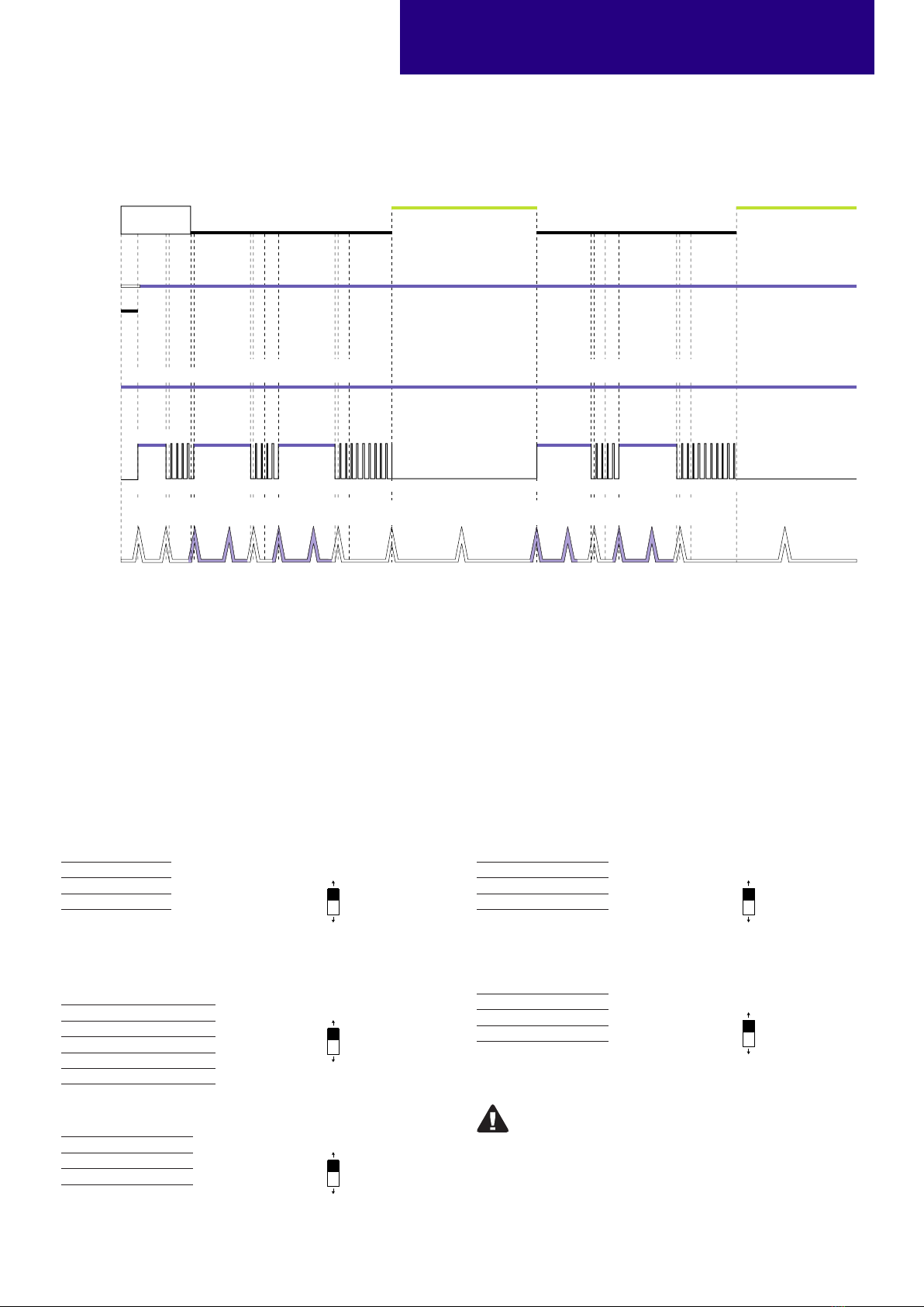
4.1 Process diagram when power on
2 3 Hold time
● ● 5 s (default)
● ○ 90 s
○ ● 300 s
○ ○ 600 s
4 Daylight sensor
●30 lux (default)
○disable
5 Standby dimming
●10 % (default)
○30 %
6 Second-order delay
●∞(default)
○10 min
1 Sensitivity
●100 % (default)
○50 %
Setting the detection area (1. code switch)
Setting the hold time (2. and 3. code switch)
●
○
ON
OFF
●
○
ON
OFF
●
○
ON
OFF
●
○
ON
OFF
●
○
ON
OFF
4.2 Adjustable code switch setting
Initialization
processNight Night
Daytime Daytime
ON
OFF
0s 5s 6s11s 12sTsT+4s
T+1s
Ts T+4s
T+1s
Ts T+4s
T+1s
Ts T+4s
T+1s
100% PWM 100% PWM 100% PWM100% PWM100% PWM
0% PWM 0% PWM 0% PWM10–30% PWM 10–30% PWM 10–30% PWM 10–30% PWM 10–30% PWM
Invalid
trigger
Invalid
trigger
Invalid
trigger
Invalid
trigger
Invalid
trigger
Invalid
trigger
Invalid
trigger
Invalid
trigger
Invalid
trigger
Trigger
valid
Trigger
valid
Trigger
valid
Trigger
valid
Continuous
trigger valid
Continuous
trigger valid
Continuous
trigger valid
Continuous
trigger valid
Model
ON / OF
F
Timing
Output
Monitor
Power losses on stand-by
system < 1 W
Power losses on stand-by
system < 1 W
In this sequence diagram, the default state of dialing is all ON state.
When the PWM output signal changes from 100 % to 10 % or 30 %, the gradual change time is 1 s, followed by a blocking time of about 3 s,
during which there is no induction.
T = the set delay time (5 s, 90 s, 300 s, 600 s) and start timing with the last valid trigger.
Within 20 s after turning on, once daylight is detected, turn off the light directly. After that, there will be a 10-minute photosensitive threshold judgment.
If the daylight continues to be detected, it will finally be judged as daytime mode, and the daytime mode induction is invalid.
When night changes to day, it also needs to pass 10 minutes of photosensitivity threshold before it is judged as day mode.
When day changes to night, it only takes 3 s to trigger directly.
When the 6. digit dialing status is OFF, if the output signal is 10 % or 30 % PWM and there is no human sensing within 10 minutes,
the output signal will become 0 % PWM.
DIP switch factory settings all default ON state.
Set the DIP switch only after mains off.
Hot plug-in is not permitted when connecting sensors.
www.tridonic.com 10
Subject to change without notice. Information provided without guarantee.
Data sheet 11/21-LC888-6
LED Driver
Linear fixed output
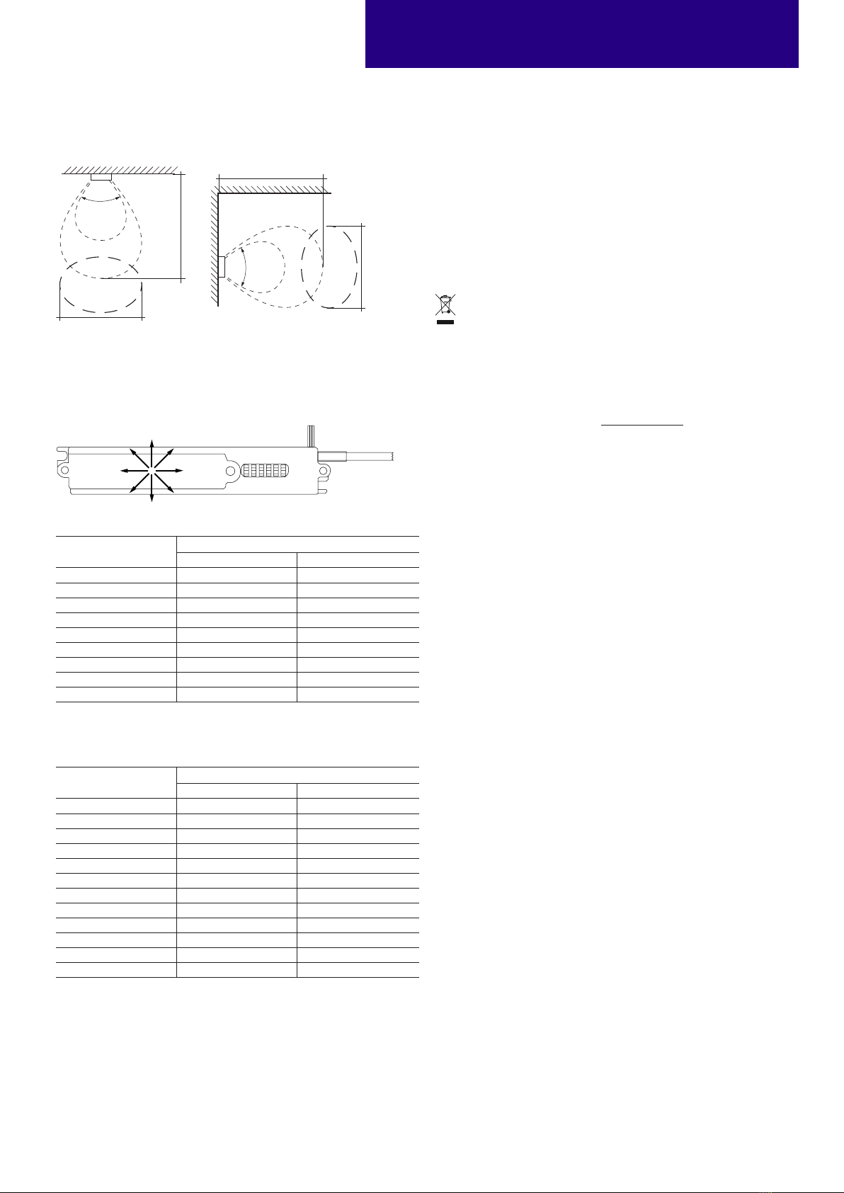
Ceiling mounted: Wall mounted:
h
d
°
4.4 Motion detection
Influence factors of detection distance:
It is related to the speed of the object.
It is related to the size of the object (the area of reception and reflection).
In the open environment and the environment with walls, the distance
difference is related to the reflection of electromagnetic waves in the face
of walls.
4.5 Detection sensibility
Optimized for detection of pedestrians with a speed of 0.5 – 1.5 m/s
corresponds to 1.8 – 5.4 km/h.
Depending on the application and environmental conditions the maximum
detectable speed of object may vary.
5. Miscellaneous
5.2 Additional information
Additional technical information at www.tridonic.com →Technical Data
Lifetime declarations are informative and represent no warranty claim.
No warranty if device was opened.
5.1 Disposal of equipment
Return old devices in accordance with the WEEE directive to suitable
recycling facilities.
h
d
°
Take 3 m as an example, the detected moving target person is:
approx. 170 cm high and weighing approx. 65 kg.
In the test room, the module is installed with the antenna facing down and
the person is moving in the direction of the sensor at a speed of 1 m/s.
A person moved towards the sensor with a speed of 1 m/s during the test in
the test room. The sensing range at different heights is as follows:
123456
ON DIP
Location 1
Location 8
Location 7
Location 6
Location 5
Location 4
Location 3
Location 2
Sensing position
Detection radius at 1 m/s moving speed
100 % sensitivity 50 % sensitivity
Location 1 4.0 m 2.0 m
Location 2 3.5 m 2.5 m
Location 3 3.5 m 2.5 m
Location 4 4.0 m 2.5 m
Location 5 4.0 m 2.5 m
Location 6 3.5 m 2.0 m
Location 7 4.0 m 2.5 m
Location 8 4.0 m 2.5 m
Overall sensing range 3.5 m 2.0 m
Application height
Detection diameter at 1 m/s moving speed
100 % sensitivity 50 % sensitivity
0.5 m 5.0 m 2.5 m
1.0 m 6.0 m 3.0 m
1.5 m 7.0 m 4.0 m
2.0 m 8.0 m 5.0 m
2.5 m 8.0 m 5.0 m
3.0 m 8.0 m 5.0 m
3.5 m 7.5 m 4.0 m
4.0 m 7.0 m 3.0 m
5.0 m 6.0 m 2.5 m
5.5 m 5.0 m 2.0 m
6.0 m 4.5 m 2.0 m
6.5 m 4.0 m 2.0 m
This manual suits for next models
1
Table of contents
Other Tridonic Lighting Equipment manuals

Tridonic
Tridonic LCA PRE OTD User manual

Tridonic
Tridonic PRO Series User manual

Tridonic
Tridonic EM converterLED ST User manual

Tridonic
Tridonic PRO Series User manual

Tridonic
Tridonic EM powerLED ST FX User manual

Tridonic
Tridonic EM converterLED BASIC 203 MH/LiFePO4 90V User manual

Tridonic
Tridonic Excite Series User manual

Tridonic
Tridonic LCAI ECO User manual

Tridonic
Tridonic EM converterLED ST MH/LiFePO4 50 V User manual

Tridonic
Tridonic BASIC Series User manual


