Tridonic PRO Series User manual
www.tridonic.com 1
Subject to change without notice. Information provided without guarantee.
Data sheet 10/20-EM091-6
Emergency lighting units
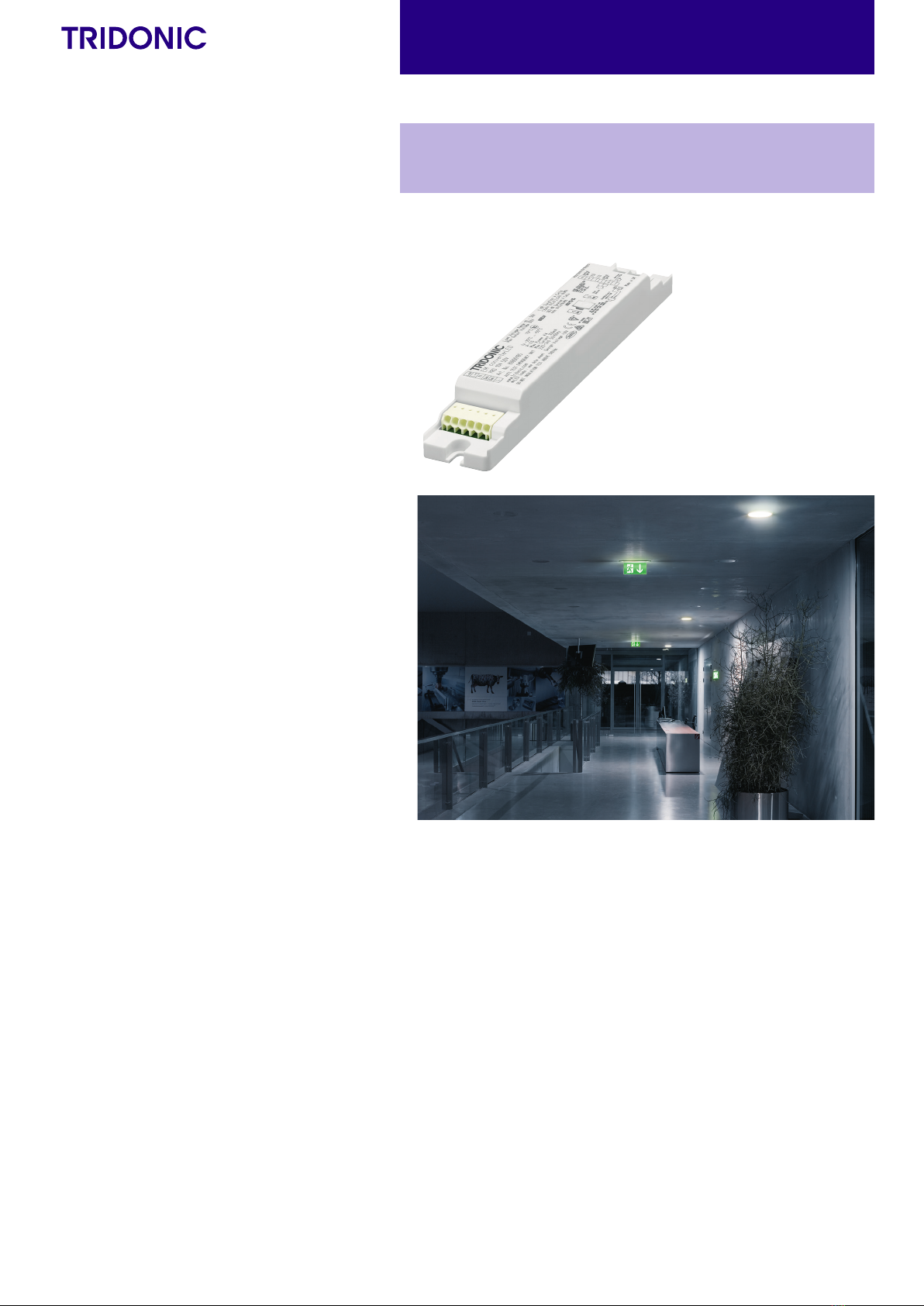
EM converterLED
Product description
• Emergency lighting LED Driver with DALI interface
and automatic test function
• For self-contained emergency lighting
• For LED modules with a forward voltage of 10 – 54 V
• SELV for output voltage < 60 V DC
• Low profile casing (21 x 30 mm cross-section)
• For luminaire installation
• Nominal life-time up to 100,000 h
• 5-year guarantee
Properties
• Non maintained operation
• DALI interface for controlled testing and monitoring
• 1, 2 or 3 h rated duration
• Operating time selectable with plug (duration link)
• Compatible with most constant current LED Drivers (see 5.4)
• 3-pole technology: 2-pole LED module changeover
and delayed power switching for the LED Driver
• Automatic shutdown of output if LED load is out of range
• Constant power output
• Addressing function, patented („EZ easy addressing“)
• Two-colour status display LED
• Electronic charge system
• Deep discharge protection
• Short-circuit-proof battery connection
• Polarity reversal protection for battery provided by 3-pole
connector
• Automatic detection of the connected battery technology
(NiMH or LiFePO4batteries)
Tests:
• Status of the battery
• Status of the LED
• Function test
• Duration test
Batteries
• High-temperature cells
• NiMH or LiFePO4 batteries
• LA or 18650 cells
• 4-year design life for NiMH batteries
• 1-year guarantee for NiMH batteries
• 4 – 8 years design life for LiFePO4batteries
• 3-year guarantee for LiFePO4batteries
• For battery compatibility refer to chapter „Battery selection“
È
Standards, page 5
Wiring diagrams and installation examples, page 6
EM converterLED PRO MH/LiFePO4 50 V
PRO series

www.tridonic.com 2
Subject to change without notice. Information provided without guarantee.
Data sheet 10/20-EM091-6
Emergency lighting units
EM converterLED
Technical data
Rated supply voltage 220 – 240 V
AC voltage range 198 – 264 V
Mains frequency 50 / 60 Hz
LED module forward voltage range 10 – 54 V
Output current see chapter 5.3
Starting time < 0.5 s from detection of emergency
event
Overvoltage protection 320 V (for 48 h)
U-OUT (including open- / short-circuit and
double load)
60 V
Max. open circuit voltage 60 V
Ambient temperature range ta -25 ... +55 °C
Max. casing temperature tc 80 °C
Mains voltage changeover threshold according to EN 60598-2-22
Mains surge capability (between L – N) 1 kV
Mains surge capability (between L/N – PE) 2 kV
Type of protection IP20
Rest mode max. number of emergency
units
100
Rest mode max. wiring distance 1,000 m
Functional test Weekly 5s test
Duration test Yearly 1 h / 2 h / 3 h test
Life-time up to 100,000 h
Dimensions LxWxH 179 x 30 x 21 mm
EM converterLED PRO MH/LiFePO4 50 V
PRO series
30
21
30
179
169.2 Position A
3 h
No duration
link 2 h
Position B
1 h
Note: LED Driver supplied with duration link in 3 hours position. Duration link must be set
before battery and mains connection.
Ordering data
Type1Article
number
Rated
duration
Packaging,
carton
Packaging,
pallet
Weight
per pc.
EM converterLED PRO 202 MH/LiFePO4 50V 1/2/3 h 10 pc(s). 1,600 pc(s).0.07 kg
EM converterLED PRO 203 MH/LiFePO4 50V 1/2/3 h 10 pc(s). 1,600 pc(s).0.07 kg
EM converterLED PRO 204 MH/LiFePO4 50V 1/2/3 h 10 pc(s). 1,600 pc(s).0.07 kg
Test switch EM3
ACCES-
SORIES
Ordering data
Type Article number Packaging,
bag
Packaging,
carton
Weight
per pc.
Test switch EM 3 25 pc(s). 200 pc(s). 0.013 kg
Status indication bi-colour LED
ACCES-
SORIES
Specific technical data
Type Battery
technology
Rated
duration
Typ. λ
(at 230 V,
50 Hz)
Typ. output
power
P emergency
Mains current in charging operation Rated power in charging operation
Initial charge Fast recharge Trickle charge2Initial charge Fast recharge Trickle charge2
EM converterLED PRO 202
MH/LiFePO4 50V
NiMH
1 h 0.65C 1.5 W 15 mA 16 mA 15 / 11 mA 1.9 W 2.2 W 1.9 / 1.4 W
2 h 0.65C 1.5 W 19 mA 19 mA 19 / 11 mA 2.6 W 2.6 W 2.6 / 1.4 W
3 h 0.65C 1.5 W 19 mA 19 mA 19 / 11 mA 2.6 W 2.6 W 2.6 / 1.4 W
LiFePO4
1 h 0.65C 1.5 W 15 mA 15 mA 15 / 11 mA 2 .1 W 2.1 W 2.1 / 1.4 W
2 h 0.65C 1.5 W 19 mA 19 mA 19 / 11 mA 2.8 W 2.8 W 2.8 / 1.4 W
3 h 0.65C 1.5 W 19 mA 19 mA 19 / 11 mA 2.8 W 2.8 W 2.8 / 1.4 W
EM converterLED PRO 203
MH/LiFePO4 50V
NiMH
1 h 0.7C 2.5 W 16 mA 18 mA 16 / 11 mA 2.1 W 2.6 W 2.1 / 1.4 W
2 h 0.7C 2.5 W 20 mA 20 mA 20 / 11 mA 3.1 W 3.1 W 3.1 / 1.4 W
3 h 0.7C 2.5 W 20 mA 20 mA 20 / 11 mA 3.1 W 3.1 W 3.1 / 1.4 W
LiFePO4
1 h 0.7C 2.5 W 19 mA 19 mA 19 / 11 mA 2.8 W 2.8 W 2.8 / 1.4 W
2 h 0.7C 2.5 W 24 mA 24 mA 24 / 11 mA 3.8 W 3.8 W 3.8 / 1.4 W
3 h 0.7C 2.5 W 24 mA 24 mA 24 / 11mA 3.8 W 3.8 W 3.8 / 1.4 W
EM converterLED PRO 204
MH/LiFePO4 50V
NiMH
1 h 0.7C 3.5 W 17 mA 20 mA 17 / 11 mA 2.3 W 2.9 W 2.3 / 1.4 W
2 h 0.7C 3.5 W 23 mA 23 mA 23 / 11 mA 3.6 W 3.6 W 3.6 / 1.4 W
3 h 0.7C 3.5 W 23 mA 23 mA 23 / 11 mA 3.6 W 3.6 W 3.6 / 1.4 W
LiFePO4
1 h 0.7C 3.5 W 19 mA 19 mA 19 / 11 mA 2.8 W 2.8 W 2.8 / 1.4 W
2 h 0.7C 3.5 W 24 mA 24 mA 24 / 11 mA 3.8 W 3.8 W 3.8 / 1.4 W
3 h 0.7C 3.5 W 24 mA 24 mA 24 / 11 mA 3.8 W 3.8 W 3.8 / 1.4 W
1 EM = Emergency
2In case of NiMH batteries: Intermittent charge is used. Value 1 is for 4 min. charge on / Value 2 is for 16 min. charge o. In case of LiFePO4 batteries voltage dependent constant current charging is used.
www.tridonic.com 3
Subject to change without notice. Information provided without guarantee.
Data sheet 10/20-EM091-6
Emergency lighting units
EM converterLED
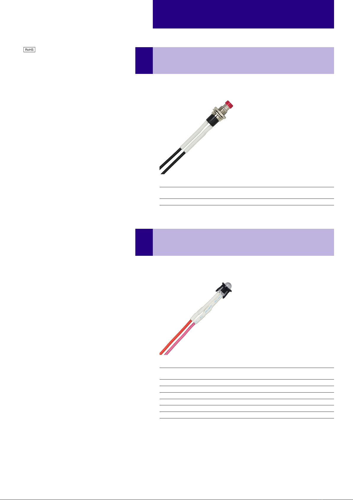
Product description
• For connection to the emergency lighting unit
• For checking the device function
• Plug connection
Test switch EM3
ACCES-
SORIES
Ordering data
Type Article number Packaging,
bag
Packaging,
carton
Weight
per pc.
Test switch EM 3 25 pc(s). 200 pc(s). 0.013 kg
Product description
• Two-colour status display LED
• Green: system OK, red: fault
• Plug connection
Status indication bi-colour LED
ACCES-
SORIES
Ordering data
Type Article number Packaging,
bag
Packaging,
carton
Weight
per pc.
LED EM bi-colour, 1.0 m CON 25 pc(s). 200 pc(s). 0.015 kg
LED EM bi-colour, high brightness HO 1.0 m CON 25 pc(s). 200 pc(s). 0.015 kg
LED EM bi-colour, 0.6 m CON 25 pc(s). 200 pc(s). 0.005 kg
LED EM bi-colour, high brightness HO 0.6 m CON 25 pc(s). 200 pc(s). 0.005 kg
LED EM bi-colour, 0.3 m CON 25 pc(s). 200 pc(s). 0.005 kg
LED EM bi-colour, high brightness HO 0.3 m CON 25 pc(s). 200 pc(s). 0.005 kg
www.tridonic.com 4
Subject to change without notice. Information provided without guarantee.
Data sheet 10/20-EM091-6
Emergency lighting units
EM converterLED
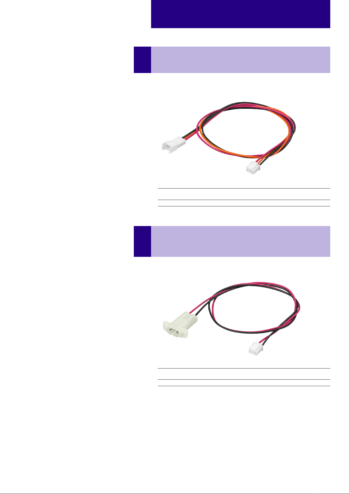
Product description
• Connection cable for NiMH batteries
• Cable length 500 mm
• 2-pole plug connection for batteries and 3-pole plug connection
for LED Driver
Connection Cable NiMH
ACCES-
SORIES
Ordering data
Type Article number Packaging,
bag
Packaging,
carton
Weight
per pc.
CONNECTION CABLE NiMH 500mm 10 pc(s). 200 pc(s). 0.015 kg
Product description
• Extension cable for LiFePO4batteries
• Cable length 500 mm
• 3-pole plug connection
Extension Cable LiFePO4
ACCES-
SORIES
Ordering data
Type Article number Packaging,
bag
Packaging,
carton
Weight
per pc.
EXTENSION CABLE LiFePO4 500mm 10 pc(s). 200 pc(s). 0.01 kg

www.tridonic.com 5
Subject to change without notice. Information provided without guarantee.
Data sheet 10/20-EM091-6
Emergency lighting units
EM converterLED
1. Standards
• EN 61347-1
• EN 61347-2-13
• EN 61347-2-7
• EN 55015
• EN 61000-3-2
• EN 61000-3-3
• EN 61547
• EN 60068-2-64
• EN 60068-2-29
• EN 60068-2-30
• EN 62384
• DALI standard EN 62386-202
• according to EN 50172
• according to EN 60598-2-22
• according to EN 62034
1.1 Glow-wire test
according to EN 61347-1 with increased temperature of 850 °C passed.
1.2 Insulation and electric strength testing of luminaires
Electronic LED-Drivers can be damaged by high voltage. This has to be consid-
ered during the routine testing of the luminaires in production.
According to IEC 60598-1 Annex Q (informative only!) or ENEC 303-Annex A,
each luminaire should be submitted to an insulation test with 500VDC for 1 sec-
ond. This test voltage should be connected between the interconnected phase
and neutral terminals and the earth terminal. The insulation resistance must be
at least 2 MΩ.
As an alternative, IEC 60598-1 Annex Q describes a test of the electrical
strength with 1,500 VAC (or 1,414 x 1,500 VDC). To avoid damage to the electronic
devices this test must not be conducted.
3. Installation / Wiring
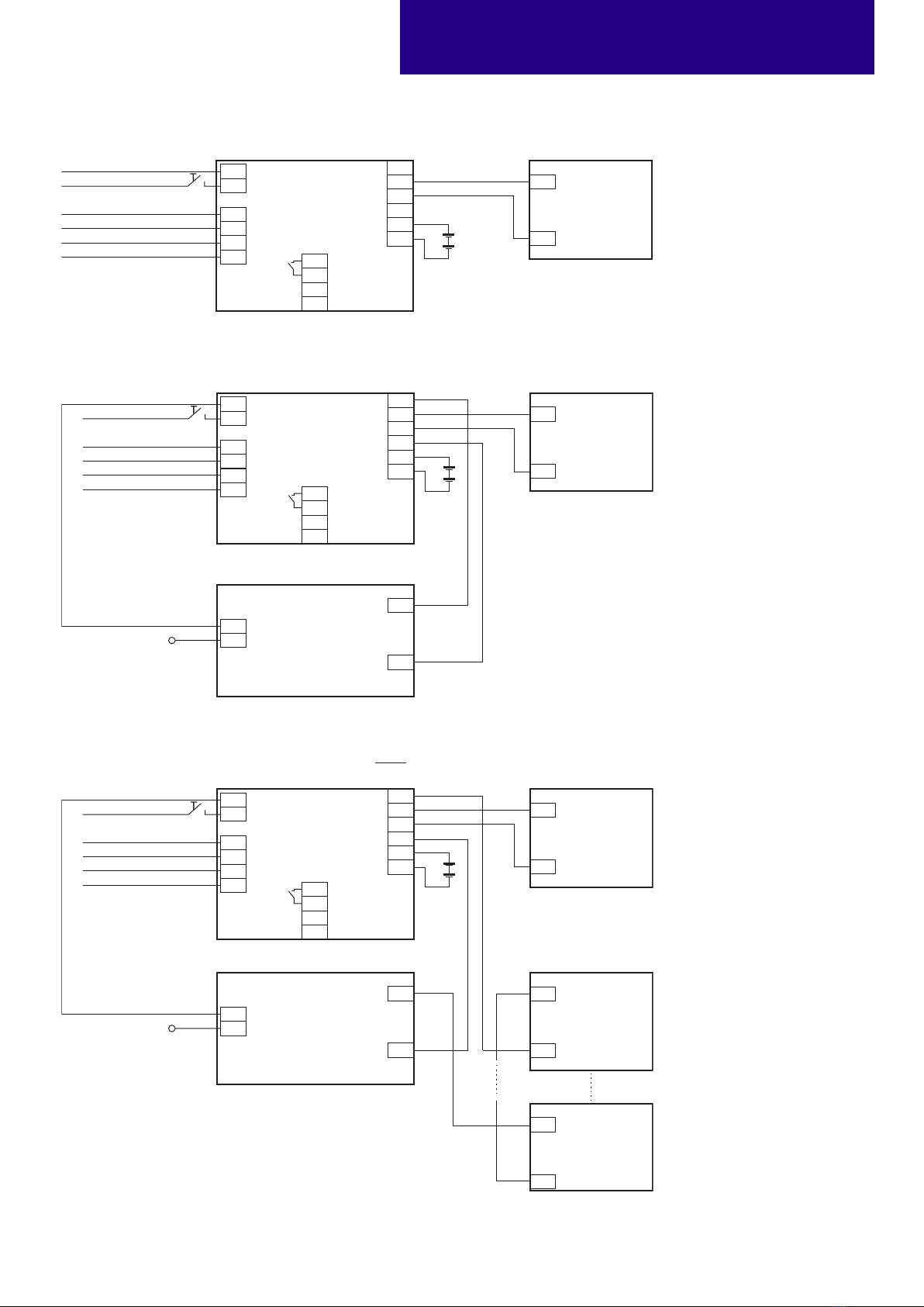
3.1 Wiring diagram
One or more LED modules with a total forward voltage of 10 to 54 V can be
connected to the EM converterLED. These LED module(s), marked with “Emer-
gency” are operated in emergency mode from the associated battery. In normal
mains mode all LED modules are operated by the mains LED Driver.
Meaning of marking
Double or reinforced insulation for built-in electronic LED Drivers. The control
gear relies upon the luminaire enclosure for protection against accidental contact
with live parts.
2. Thermal details and life-time
2.1 Life-time
Average life-time 50,000 hours under rated conditions with a failure rate of
less than 10 %. Average failure rate of 0.2 % per 1000 operating hours.
Expected life-time with LiFePO4batteries
EM converterLED PRO 202
MH/LiFePO4 50V
tc 65 °C 70 °C 75 °C 80 °C
life-time > 100,000 h > 100,000 h > 100,000 h > 79,000 h
EM converterLED PRO 203
MH/LiFePO4 50V
tc 65 °C 70 °C 75 °C 80 °C
life-time > 100,000 h > 100,000 h > 100,000 h > 78,000 h
EM converterLED PRO 204
MH/LiFePO4 50V
tc 65 °C 70 °C 75 °C 80 °C
life-time > 100,000 h > 100,000 h > 100,000 h > 78,000 h
The emergency lighting LED Driver is designed for a life-time stated above
under reference conditions and with a failure probability of less than 10 %.
The relation of tc to ta temperature depends also on the luminaire design.
If the measured tc temperature is approx. 5 K below tc max., ta tempera-
ture should be checked and eventually critical components (e.g. ELCAP)
measured. Detailed information on request.
Expected life-time with NiMH batteries
EM converterLED PRO 202
MH/LiFePO4 50V
tc 65 °C 70 °C 75 °C 80 °C
life-time > 100,000 h > 100,000 h > 100,000 h 73,000 h
EM converterLED PRO 203
MH/LiFePO4 50V
tc 65 °C 70 °C 75 °C 80 °C
life-time > 100,000 h > 100,000 h 99,000 h 70,000 h
EM converterLED PRO 204
MH/LiFePO4 50V
tc 65 °C 70 °C 75 °C 80 °C
life-time > 100,000 h > 100,000 h 96,000 h 68,000 h
www.tridonic.com 6
Subject to change without notice. Information provided without guarantee.
Data sheet 10/20-EM091-6
Emergency lighting units
EM converterLED
Neutral
+
+
–
–
+
––
+
P
O
Lout
Lin
N
Dali
Dali
L
L
N
EM ConverterLED
PRO
Neutral
Dali
Dali
Un-Switched Line Test
switch
Indicator
LED
Switched Line out
Switched Line in
Control gear
LED
LED
Control gear
Battery
Battery
LED Module
Emergency
–
+
–
+
LED Module
–
+
LED Module
LED control gear
max. 150 W in operation
EM converterLED PRO with one LED module for non-maintained emergency operation
EM converterLED PRO with a standard LED LED Driver and one LED module for mains and emergency operation
EM converterLED PRO with a standard LED LED Driver and series operation of LED modules
Neutral
+
+
–
–
+
––
+
P
O
Lout
Lin
N
Dali
Dali
L
L
N
EM ConverterLED
PRO
Neutral
Dali
Dali
Un-Switched Line Test
switch
Indicator
LED
Switched Line out
Switched Line in
Control gear
LED
LED
Control gear
Battery
Battery
LED Module
Emergency
–
+
LED control gear
max. 150 W in operation
+
+
–
–
+
––
+
P
O
Lout
Lin
N
Dali
Dali
L
EM ConverterLED
PRO
Neutral
Dali
Dali
Un-Switched Line Test
switch
Indicator
LED
Not connected
Not connected
Control gear
LED
LED
Control gear
Battery
Battery
LED Module
Emergency
One LED module is operated in emergency mode.
All LED modules are operated in mains mode.

www.tridonic.com 7
Subject to change without notice. Information provided without guarantee.
Data sheet 10/20-EM091-6
Emergency lighting units
EM converterLED
EM converterLED PRO with a standard LED LED Driver and parallel operation of LED modules
Neutral
+
+
–
–
+
––
+
P
O
L
N
EM ConverterLED
PRO
Test
switch
Indicator
LED
Control gear
LED
LED
Control gear
Battery
Battery
LED Module
Emergency
–
+
–
+
LED Module
–
+
LED Module
LED control gear
max. 150 W in operation
Lout
Lin
N
Dali
Dali
L
Neutral
Dali
Dali
Un-Switched Line
Switched Line out
Switched Line in
One LED module is operated in emergency mode.
All LED modules are operated in mains mode.
8 – 9 mm
wire preparation:
0.5 – 1.5 mm²
3.2 Wiring type and cross section
Solid wire with a cross section of 0.5 – 1.5 mm². Strip 8 – 9 mm of insulation
from the cables to ensure perfect operation of terminals.
Wiring: LED module/LED Driver/supply
3.3 Battery connection
LiFePO4: Direct connection
NiMH: Connection with extension
When using an EM converterLED in combination with a NiMH battery, order the
CONNECTION CABLE NiMH 500mm seperately.
LiFePO4: Connection with extension
Battery
300
EM converterLED
Battery
500
300
EM converterLED
Battery
500
300
EM converterLED

www.tridonic.com 8
Subject to change without notice. Information provided without guarantee.
Data sheet 10/20-EM091-6
Emergency lighting units
EM converterLED
3.4 Loose wiring
Loosen wire through twisting
and pulling or using a Ø1 mm
release tool
3.5 Wiring guidelines
• The LED terminals, battery, indicator LED and test switch terminals are clas-
sified as SELV (output voltage < 60 V DC). Keep the wiring of the input termi-
nals separated from the wiring of the SELV equivalent terminals or consider
special wiring (double insulation, 6 mm creepage and clearance) when these
connections should be kept SELV.
• The output to the LED is DC but has high frequency content, which should be
considered for good EMC compliance.
• LED leads should be separated from the mains and DALI connections and
wiring for good EMC performance.
• Maximum lead length on the LED terminals is 3 m. For a good EMC
performance keep the LED wiring as short as possible.
• The secondary wires (LED module) should be routed in parallel to ensure
good EMC performance.
• Maximum lead length for the Test switch and Indicator LED connection is 1 m.
The test switch and Indicator LED wiring should be separated from the LED
leads to prevent noise coupling.
• Battery leads are specified with 0.5 mm cross section and a length of 0.8 m
• DALI terminals are mains proof
• To avoid the damage of the control gear, the wiring must be protected against
short circuits to earth (sharp edged metal parts, metal cable clips, louver, etc.)
To ensure that a luminaire containing LED emergency units complies with EN
55015 for radio frequency conducted interference in both normal and emergency
mode it is essential to follow good practice in the wiring layout.
Within the luminaire the switched and unswitched 50 Hz supply wiring must be
routed as short as possible and be kept as far away as possible from the LED
leads.Through wiring may affect the emc performance of the luminaire.
The length of LED leads to the LED module must not be exceeded. Note that
the length of the EM converterLED leads to the LED module is added to the
length of the leads from the LED Driver to the EM converterLED module when
considering the max. permitted lead length of the LED Driver.
3.6 Maximum lead length
LED 3 m (6 m loop)1
Status indication LED 1 m
Batteries 0.8 m
1Note: The length of LED leads to the LED module must not be exceeded. Note that the length
of the EM converterLED leads is added to the length of the leads from the LED Driver to the EM
converterLED module when considering max. permitted lead length of the LED Driver. Leads
should always be kept as short as possible.
3.7 Use of different phases
The use of different phases for switched line and unswitched line is allowed.
When using different phases, the unswitched line must fail if the switched
line fails. This is required to assure correct switching into emergency mode. It
can be realised with a relay.
4. Mechanical values
4.1 Housing properties
• Casing manufactured from polycarbonate.
• Type of protection: IP20
• Max. torque at the mounting screws: 0.8 Nm
4.2 Mechanical data accessories
LED status indicator
• Bi-colour
• Mounting hole 6.5 mm diameter, 1 – 1.6 mm thickness
• Lead length 0.3 m / 1.0 m
• Insulation rating: 90 °C
• Plug connection
Test switch
• Mounting hole 7.0 mm diameter
• Lead length 0.55 m
• Plug connection
Battery connection
• Plug connection 0.3 m
• Extension 0.5 m

www.tridonic.com 9
Subject to change without notice. Information provided without guarantee.
Data sheet 10/20-EM091-6
Emergency lighting units
EM converterLED
Automatic circuit breaker type B10 B13 B16 B20 C10 C13 C16 C20 Inrush current
Installation Ø1.5 mm21.5 mm21.5 mm22.5 mm21.5 mm21.5 mm21.5 mm22.5 mm2Imax time
EM converterLED PRO MH/LiFePO4 50V 90 130 130 130 180 260 260 260 10 A 120 μs
5. Electrical values
5.1 Maximum loading of automatic circuit breakers
5.2 Insulation matrix
Mains Switched Live Battery, LED, Test
switch, Indicator LED DALI
Mains – • • • •
Switched Live • – • • •
Battery, LED, Test
switch, Indicator LED • • • • – •
DALI • • • –
• Represents basic insulation
• • Represents double or reinforced insulation
When using a non-SELV LED Driver insulate the battery, LED, test switch and indicator LED in the luminaire according to the
U-OUT rating of the LED Driver.

www.tridonic.com 10
Subject to change without notice. Information provided without guarantee.
Data sheet 10/20-EM091-6
Emergency lighting units
EM converterLED
5.3 Typ. LED current/voltage characteristics
The LED current in emergency mode is automatically adjusted by the EM converterLED module based on the total forward voltage of the LED modules con-
nected and the associated battery. The start of the LED in emergency mode does not result in a current peak.
EM converterLED PRO 202 MH/LiFePO4 50V
Article number: 89800627
NiMH battery, 2.4 V battery voltage
730 – 790 mA battery discharge current (tolerance)
LiFePO4battery, 3.2 V battery voltage
530 – 570 mA battery discharge current (tolerance)
EM converterLED PRO 203 MH/LiFePO4 50V
Article number: 89800628
NiMH battery, 3.6 V battery voltage
890 – 960 mA battery discharge current (tolerance)
LiFePO4battery, 3.2 V battery voltage
770 – 830 mA battery discharge current (tolerance)
LED current [mA]
VLED [V] VLED [V]
LED current [mA]
EM converterLED PRO 204 MH/LiFePO4 50V
Article number: 89800629
NiMH battery, 4.8 V battery voltage
785 – 845 mA battery discharge current (tolerance)
LiFePO4battery, 3.2 V battery voltage
1,255 – 1,350 mA battery discharge current (tolerance)
LED current [mA]
VLED [V]
LED current at nominal battery voltage and
min. battery discharge current
LED current at nominal battery voltage and
max. battery discharge current
0302010 40 50 60
20
40
60
0
100
120
140
80
160
0302010 40 50 60
50
0
100
150
200
250
300
0302010 40 50 60
50
0
100
150
200
250
300
350
400

www.tridonic.com 11
Subject to change without notice. Information provided without guarantee.
Data sheet 10/20-EM091-6
Emergency lighting units
EM converterLED
6.2 Status indication
System status is indicated by a bi-colour LED and by a DALI status flag.
LED indication Status Comment
Permanent green System OK AC mode
Fast flashing green
(0,1 sec on – 0,1 sec o)
Function test
underway
Slow flashing green
(1 sec on – 1 sec o)
Duration test
underway
Red LED on Load failure Open circuit / Short circuit / LED failure
Slow flashing red
(1 sec on – 1 sec o)
Battery failure Battery failed the duration test or function
test / Battery is defect or deep discharged/
Incorrect battery voltage
Fast flashing red
(0,1 sec on – 0,1 sec o)
Charging failure Incorrect charging current
Double pulsing green Inhibit mode Switching into inhibit mode via controller
Binary transmission of address
via green/red LED
Address
identification During address identification mode
Green and red o DC mode Battery operation (emergency mode)
6.3 Testing
DALI Control
A DALI command from a suitable control unit can be used to initiate func-
tion and duration tests at individually selected times. Status flags are set for
report back and data logging of results.
When a DALI bus has not been connected or when a DALI bus is connected
but the DALI default DELAY and INTERVAL times have not been re-set
by sending appropriate DALI commands, then the EM converterLED PRO
will conduct self-tests in accordance with the default times set within the
EEPROM.
These default times are factory pre-set, in accordance with the DALI stan-
dard EN 62386-202, to conduct an automatic function test every 7 days and
a duration test every 52 weeks. Since the DELAY time is factory pre-set to
Zero, all units are tested at the same time. Test times can be changed with a
command over the DALI bus.
The DELAY and INTERVAL time values must be re-set when the emergency
system test times are to be scheduled by a DALI control and monitoring
system.
Note that once the default values have been set to Zero, tests will only be
conducted following a command from the control system. If the DALI bus is
disconnected the EM converterLED PRO does not revert to self-testing
mode.
Note: If the battery is connected the DALI communication is only possible
after power reset.
Addressing
The EM converterLED PRO includes the EZ easy addressing system which
allows addressing and identification by using the bi-colour LED. Binary
address codes given by the LED can be simply converted to the DALI
addresses 0 to 63. For single handed addressing using this method it is
necessary to send a broadcast ident command every 3 to 9 seconds. During
this command the LEDs will be switched off and the indication LED will flash
the 6 bit binary address preceded by a 3 second start indication period.
5.4 LED Driver compatibility
The EM converterLED emergency unit use 3 pole technology and is compa-
tible with most LED Drivers on the market, however it is important to check
that the rating of the LED Driver does not exceed the values specified below:
• The max. allowed output current rating of the associated LED Driver is
2.4 A peak (current rating of switching relays of EM converterLED)
• The max. allowed inrush current rating of the associated LED Driver is
60 A peak for 1 ms or 84 A for 255 μs (inrush current rating of switching
relay of EM converterLED)
• The max. allowed output voltage of the associated LED Driver applied to
the EM converterLED output is 450V (voltage withstand between adja-
cent contact of the single switching relay of the EM converterLED)
• The max. allowed LED load of the associated LED Driver is 150 W in
operation. The load must be an LED module.
Check compatibility with the carried out function test (duration at least 5
seconds) individually for each device.
6. Functions
6.1 Duration link selection
Emergency lighting LED Driver supplied with duration link in 3 hours positi-
on (position A).
The position of the link will only be read on first power up. If it is changed
afterwards both the battery and mains supply must be disconnected for 10
seconds to enable the EM converterLED to read the new link position on
reconnection of the battery and mains. It will lead to a false battery failure
indication if the link is changed after installation without this reset.
2 hr
3 hr
No duration link
Position A
Duration Link position
1 hr
Position B

www.tridonic.com 12
Subject to change without notice. Information provided without guarantee.
Data sheet 10/20-EM091-6
Emergency lighting units
EM converterLED
Commissioning
After installation of the luminaire and initial connection of the mains supply
and battery supply to the EM converterLED PRO the unit will commence
charging the batteries for 20 hours (initial charge). Afterwards the module
will conduct a commissioning test for the full duration. The 20 hours rechar-
ge occurs also if a new battery is connected or the module exits the rest
mode condition. The following automatic commissioning duration test is only
performed when a battery is replaced and fully charged (after 20 hrs) and
the interval time is not set to zero, otherwise the system is expected to per-
form the testing.
Functional test
The time of day and frequency of the 5 seconds function test can be set by
the DALI controller. The default setting is a 5 seconds test on a weekly basis.
Duration test
The time of day and frequency of the duration test can be set by the DALI
controller. The default setting is a duration test conducted every 52 weeks.
For 2 h operation:
The first commissioning duration test has a time of 120 minutes, subse-
quent through life tests are conducted for 90 minutes. When the battery is
changed or disconnected and re-connected the unit will next conduct a 120
minute test.
Prolong time
Prolong time can be set by the DALI controller. This is the delay time bet-
ween return of the mains supply and the end of the emergency operation.
The default prolong time is set as 0 minutes as specified within the DALI
standard.
Indicator LED will stay off for the duration of the prolong time.
Test switch
An optional test switch can be wired to each EM converterLED.
This can be used to to:
• Initiate a 5 seconds function test: press 200 ms < T < 1 s
• Execute function test as long as switch pressed: press > 1 s
• Reset selftest timer (adjust local timing): press > 10 s
Rest Mode / Inhibit Mode
Emergency operation is automatically started when the mains supply is
switched off. If the Rest Mode is activated, the discharging of the battery will
be minimized by switching off the LED output. If the Inhibit Mode has been
activated before the mains supply is switched off, Rest Mode will be automa-
tically switched on if the mains supply is switched off within 15 minutes.
Rest Mode and Inhibit Mode can be initiated by the DALI controller. The
REST command has to be sent after the mains supply has been discon-
nected and whilst the EM converterLED PRO is in emergency operation.
The INHIBIT command has to be sent while the EM converterLED PRO is
supplied by mains.
After a mains reset the EM converterLED PRO exits the Rest Mode. Rest
Mode and Inhibit Mode can both be disabled by sending the RE-LIGHT/
RESET INHIBIT command.
The EM converterLED PRO 202 does not support the Rest Mode / Inhibit
Mode.
Timer reset functionality
The timer for function and duration test can be set to a particular time of the
day by either pressing the test switch for longer than 10 seconds or cycling
the unswitched line supply 5 times within 1 minute. The timer adjustment
will enable the test start time to be defined manually at time in day when
the timer was reset. It will also disable the adaptive test algorithm thereby
forcing the unit to perform the test at the same time rather than it being
defined by the adaptive algorithm. This function will only work provided the
interval time is greater than zero (automatic test mode enabled). The delay
timer value set when the unit was commissioned will be reloaded in order to
randomise the tests between adjacent units.
DALI Controller
DALI controllers and hardware/software solutions are available from
Tridonic. Please refer to the Lighting controls section.
www.tridonic.com 13
Subject to change without notice. Information provided without guarantee.
Data sheet 10/20-EM091-6
Emergency lighting units
EM converterLED
7. Battery data
7.1 Battery selection
7.2 Battery charge / discharge data
EM converterLED PRO, 1 / 2 / 3 h
Type EM converterLED PRO
202 MH/LiFePO4 50V
EM converterLED PRO
203 MH/LiFePO4 50V
EM converterLED PRO
204 MH/LiFePO4 50V
Article no. 89800627 89800628 89800629
Duration 1 h 2/3 h 1 h 2/3 h 1 h 2/3 h
Technology and
capacity
Design Number
of cells
Type Article no. Assignable batteries
NiMH 4.0 Ah
LA cells
stick 1 x 2 Accu-NiMH 2A CON •
stick 1 x 3 Accu-NiMH 3A CON •
stick 1 x 4 Accu-NiMH 4A CON •
stick + stick 2 + 2 Accu-NiMH 4C CON •
LiFePO4 1.5 Ah
18650 cells
stick 1 x 1 Accu-LiFePO4 1A CON •
stick 1 x 2 Accu-LiFePO4 2A CON • • •
stick 1 x 4 Accu-LiFePO4 4A CON •
stick 1 x 5 Accu-LiFePO4 5A CON •
stick + stick 2 + 2 Accu-LiFePO4 4C CON •
stick + stick 3 + 2 Accu-LiFePO4 5C CON •
side by side 2 x 1 Accu-LiFePO4 2B CON • • •
side by side 4 x 1 Accu-LiFePO4 4B CON •
side by side 5 x 1 Accu-LiFePO4 5B CON •
EM converterLED PRO, 1 / 2 / 3 h, NiMH
Type EM converterLED PRO
202 MH/LiFePO4 50V
EM converterLED PRO
203 MH/LiFePO4 50V
EM converterLED PRO
204 MH/LiFePO4 50V
Article no. 89800627 89800628 89800629
Duration 1 h 2/3 h 1 h 2/3 h 1 h 2/3 h
Battery charge
time
Initial charge 20 h
Fast recharge 10 h 15 h 10 h 15 h 10 h 15 h
Trickle charge continuously
Charging current
Initial charge 110 – 150 mA 280 – 320 mA 110 – 150 mA 280 – 320 mA 110 – 150 mA 280 – 320 mA
Fast recharge 190 – 230 mA 310 – 350 mA 190 – 230 mA 310 – 350 mA 190 – 230 mA 310 – 350 mA
Trickle charge 110 – 150 mA / 4 min.
0 mA / 16 min.
180 – 220 mA / 4 min.
0 mA / 16 min.
110 – 150 mA / 4 min.
0 mA / 16 min.
180 – 220 mA / 4 min.
0 mA / 16 min.
110 – 150 mA / 4 min.
0 mA / 16 min.
180 – 220 mA / 4 min.
0 mA / 16 min.
Discharge current 730 – 790 mA 730 – 790 mA 770 – 830 mA 770 – 830 mA 785 – 845 mA 785 – 845 mA
Charge voltage range10.9 – 1.65 V per cell
Discharge voltage range 1.65 – 1.05 V per cell
1The battery will be charged below 0.9 V. The EM converterLED will indicate a battery fault.
The emergency lighting LED Driver will recharge the battery normally after running the test of 61347-2-7 CL 22.3 (abnormal operating conditions).

www.tridonic.com 14
Subject to change without notice. Information provided without guarantee.
Data sheet 10/20-EM091-6
Emergency lighting units
EM converterLED
EM converterLED PRO, 1 / 2 / 3 h, LiFePO4
Type EM converterLED PRO
202 MH/LiFePO4 50V
EM converterLED PRO
203 MH/LiFePO4 50V
EM converterLED PRO
204 MH/LiFePO4 50V
Article no. 89800627 89800628 89800629
Duration 1 h 2/3 h 1 h 2/3 h 1 h 2/3 h
Battery charge
time
Initial charge 24 h
Fast recharge 24 h
Trickle charge continuously and battery voltage controlled
Charging current
Initial charge 115 – 155 mA 250 – 290 mA 250 – 290 mA 430 – 470 mA 250 – 290 mA 430 – 470 mA
Fast recharge 115 – 155 mA 250 – 290 mA 250 – 290 mA 430 – 470 mA 250 – 290 mA 430 – 470 mA
Trickle charge1115 – 155 mA / 0 mA 250 – 290 mA / 0 mA 250 – 290 mA / 0 mA 430 – 470 mA / 0 mA 250 – 290 mA / 0 mA 430 – 470 mA / 0 mA
Discharge current 530 – 570 mA 530 – 570 mA 890 – 960 mA 890 – 960 mA 1,255 – 1,350 mA 1,255 – 1,350 mA
Charge voltage range22.0 – 3.65 V
Discharge voltage range 3.65 – 2.60 V
1Automatic recharge when battery voltage falls below 3.4 V. Charger o (0 mA) when battery voltage exceeds 3.6 V.
Note: Battery protected against operation at excessive temperatures (charging stopped when battery cell temperature < -5 °C or > 60 °C).
The emergency lighting LED Driver will recharge the battery normally after running the test of 61347-2-7 CL 22.3 (abnormal operating conditions).
2The battery will not be charged below 2.0 V.
7.3 Accu-NiMh
Capacity 4.0 Ah
International designation HRMU 19/90
Battery voltage/cell 1.2 V
Cell type LA
Case temperature range
to ensure 4 years design life +5 °C to +50 °C
Max. short term temperature (reduced life-time) 70 °C
Max. number discharge cycles 4 cycles per year plus
30 cycles during
comissioning
Max. storage time 12 months
at +5 °C to +25 °C
7.4 Accu-LiFePO4
Capacity 1.5 Ah
International designation IFpR 19/66
Battery voltage/cell 3.2 V
Cell type 18650
Case temperature range to ensure
4 years design life +5 °C to +55 °C
6 years design life +5 °C to +45 °C
8 years design life +5 °C to +35 °C
Max. short term temperature (reduced life-time) 70 °C
Max. number discharge cycles 50 cycles total
Max. storage time 12 months
at +5 °C to +25 °C
Only use Tridonic batteries.
Comply with UN 38.3 and IEC 62133 (safety testing) protected against over
charge, over discharge, charging at excessive temperatures, short-circuit and
over current.
7.6 Storage, installation and commissioning
Relevant information about storage conditions, installation and commissioning
are provided in the battery datasheets.
Activating NiMH batteries:
In order to activate new batteries, 2-3 full charge-discharge cycles could be
needed. This activating process is defined by charging (24 h) and discharging
(1/2/3 h) of the batteries. If the first duration test fails, please repeat the test
after a 24 hour charging period.
7.5 Safety
7.5.1 Deep discharge protection
When the battery remains connected without charging for a long period of time
after the battery cut off of the driver the battery voltage can still drop. To make
sure the cells are not damaged by this voltage drop, the battery protection
prevents the battery from further discharge below 2.0 V.
7.5.2 Overcharge protection
If in case of an error or the use of a wrong driver the battery gets overcharged
the battery protection will disconnect the battery from the driver at a voltage of
3.9 V. A discharge of the battery is still possible after the protection circuit was
triggered to guarantee emergency operation.
7.5.3 Short-circuit protection
In case of a short circuit the battery protection opens the connection to the
driver and the output is therefore free of voltage. The output will be reactivated
again when the short circuit is removed.
7.5.4 Overtemperature protection
The battery is protected against temporary thermal overheating. If the tempera-
ture limit is exceeded the further charging of the battery is no longer possible.
The temperature protection is activated below approx. 0 °C and above approx.
+60 °C. The discharging of the battery is still possible to guarantee emergency
operation.

www.tridonic.com 15
Subject to change without notice. Information provided without guarantee.
Data sheet 10/20-EM091-6
Emergency lighting units
EM converterLED
8. Miscellaneous
8.1 Maximum number of switching cycles
EM converterLEDs are tested with 50,000 mains switching cycles of the
associated LED driver.
8.2 Battery replacement
After a battery replacement and a subsequent full charge cycle (24 h) a
duration test is mandatory to prove that with the new battery the rated
duration is achieved.
8.3 BlackBox data recording
Several parameters in respect to the application and use of the product are
stored in the EM converterLED. The parameters provide information about
the mains, battery, LED output and emergency operation.
The BlackBox can be read out with the masterCONFIGURATOR and
deviceANALYSER.
In order to allow a safe detection of a battery replacement through the “Black
Box data recording” follow the below described process.
Battery replacement
1. Disconnect mains
2. Disconnect battery
3. Reconnect and disconnect mains while no battery is not connected1
4. Connect new battery
5. Connect mains2
1Battery fault is safely recorded by the EM converterLED
2Connection of new battery is recorded by the EM converterLED
8.4 Additional information
Additional technical information at www.tridonic.com →Technical Data
Guarantee conditions at www.tridonic.com →Services
Life-time declarations are informative and represent no warranty claim.
No warranty if device was opened.
Other manuals for PRO Series
1
This manual suits for next models
7
Table of contents
Other Tridonic Lighting Equipment manuals

Tridonic
Tridonic Excite Series User manual

Tridonic
Tridonic Essence LC 35W 200-350mA stepDIM lp SNC User manual

Tridonic
Tridonic EM ready2apply SELFTEST 2 W SM User manual

Tridonic
Tridonic LCAI ECO User manual

Tridonic
Tridonic EM powerLED ST FX User manual

Tridonic
Tridonic PRO Series User manual

Tridonic
Tridonic EM converterLED ST MH/LiFePO4 50 V User manual

Tridonic
Tridonic LCA PRE OTD User manual

Tridonic
Tridonic EM converterLED BASIC 203 MH/LiFePO4 90V User manual

Tridonic
Tridonic EM converterLED ST User manual


