Tridonic EM converterLED ST User manual

ø4,5
41
82
175
34
183
34
209
ø4,5
33
82
175,5
175
34
183
82
34
209
175
34
183
ø4,5
41
82
34
209
175,5
175
34
183
ø4,5
33
82
34
209
LED Driver
EM converterLED ST
Product Manual

Product manual EM converterLED ST | 08-2018 | 1.0 | en
Table of Contents
c2 / 38
Scope of documentation 4
Validity . . . . . . . . . . . . . . . . . . . . . . . . . . . . . . . . . . . . . . . . . . . . . . . . . . . . . . . . . . . . . . . . . . . . . . . . . . . . . . . . . . . . . . . . . . . . . . . . . . . . . . . . . . . . . . . . . . . . . . 4
Copyright . . . . . . . . . . . . . . . . . . . . . . . . . . . . . . . . . . . . . . . . . . . . . . . . . . . . . . . . . . . . . . . . . . . . . . . . . . . . . . . . . . . . . . . . . . . . . . . . . . . . . . . . . . . . . . . . . . . . 4
Imprint . . . . . . . . . . . . . . . . . . . . . . . . . . . . . . . . . . . . . . . . . . . . . . . . . . . . . . . . . . . . . . . . . . . . . . . . . . . . . . . . . . . . . . . . . . . . . . . . . . . . . . . . . . . . . . . . . . . . . . 4
Safety instructions 5
Intended use . . . . . . . . . . . . . . . . . . . . . . . . . . . . . . . . . . . . . . . . . . . . . . . . . . . . . . . . . . . . . . . . . . . . . . . . . . . . . . . . . . . . . . . . . . . . . . . . . . . . . . . . . . . . . . . . . 5
Dangers associated with the operation of the system . . . . . . . . . . . . . . . . . . . . . . . . . . . . . . . . . . . . . . . . . . . . . . . . . . . . . . . . . . . . . . . . . . . . . . . . . . 5
Environment . . . . . . . . . . . . . . . . . . . . . . . . . . . . . . . . . . . . . . . . . . . . . . . . . . . . . . . . . . . . . . . . . . . . . . . . . . . . . . . . . . . . . . . . . . . . . . . . . . . . . . . . . . . . . . . . . 5
Additional instructions . . . . . . . . . . . . . . . . . . . . . . . . . . . . . . . . . . . . . . . . . . . . . . . . . . . . . . . . . . . . . . . . . . . . . . . . . . . . . . . . . . . . . . . . . . . . . . . . . . . . . . . 6
Introduction 7
About the device . . . . . . . . . . . . . . . . . . . . . . . . . . . . . . . . . . . . . . . . . . . . . . . . . . . . . . . . . . . . . . . . . . . . . . . . . . . . . . . . . . . . . . . . . . . . . . . . . . . . . . . . . . . . . 7
Testing of emergency systems . . . . . . . . . . . . . . . . . . . . . . . . . . . . . . . . . . . . . . . . . . . . . . . . . . . . . . . . . . . . . . . . . . . . . . . . . . . . . . . . . . . . . . . . . . . . . . . . 7
Portfolio of products 8
Housing . . . . . . . . . . . . . . . . . . . . . . . . . . . . . . . . . . . . . . . . . . . . . . . . . . . . . . . . . . . . . . . . . . . . . . . . . . . . . . . . . . . . . . . . . . . . . . . . . . . . . . . . . . . . . . . . . . . . . 8
Forward voltage . . . . . . . . . . . . . . . . . . . . . . . . . . . . . . . . . . . . . . . . . . . . . . . . . . . . . . . . . . . . . . . . . . . . . . . . . . . . . . . . . . . . . . . . . . . . . . . . . . . . . . . . . . . . . . 8
Functions in emergency operation 9
Adjustable output current . . . . . . . . . . . . . . . . . . . . . . . . . . . . . . . . . . . . . . . . . . . . . . . . . . . . . . . . . . . . . . . . . . . . . . . . . . . . . . . . . . . . . . . . . . . . . . . . . . . 10
Intelligent multilevel charging system . . . . . . . . . . . . . . . . . . . . . . . . . . . . . . . . . . . . . . . . . . . . . . . . . . . . . . . . . . . . . . . . . . . . . . . . . . . . . . . . . . . . . . . . 13
Rest mode, Inhibit mode and Relight command . . . . . . . . . . . . . . . . . . . . . . . . . . . . . . . . . . . . . . . . . . . . . . . . . . . . . . . . . . . . . . . . . . . . . . . . . . . . . . . 14
Indicator LED . . . . . . . . . . . . . . . . . . . . . . . . . . . . . . . . . . . . . . . . . . . . . . . . . . . . . . . . . . . . . . . . . . . . . . . . . . . . . . . . . . . . . . . . . . . . . . . . . . . . . . . . . . . . . . . 17
Settings for Emergency tests 19
Test times and test intervals . . . . . . . . . . . . . . . . . . . . . . . . . . . . . . . . . . . . . . . . . . . . . . . . . . . . . . . . . . . . . . . . . . . . . . . . . . . . . . . . . . . . . . . . . . . . . . . . 20
Commissioning test . . . . . . . . . . . . . . . . . . . . . . . . . . . . . . . . . . . . . . . . . . . . . . . . . . . . . . . . . . . . . . . . . . . . . . . . . . . . . . . . . . . . . . . . . . . . . . . . . . . . . . . . . 20
Weekly function test . . . . . . . . . . . . . . . . . . . . . . . . . . . . . . . . . . . . . . . . . . . . . . . . . . . . . . . . . . . . . . . . . . . . . . . . . . . . . . . . . . . . . . . . . . . . . . . . . . . . . . . . . 21
Annual duration test . . . . . . . . . . . . . . . . . . . . . . . . . . . . . . . . . . . . . . . . . . . . . . . . . . . . . . . . . . . . . . . . . . . . . . . . . . . . . . . . . . . . . . . . . . . . . . . . . . . . . . . . 22
Adaptive test mode . . . . . . . . . . . . . . . . . . . . . . . . . . . . . . . . . . . . . . . . . . . . . . . . . . . . . . . . . . . . . . . . . . . . . . . . . . . . . . . . . . . . . . . . . . . . . . . . . . . . . . . . . 22
Functionality of the test switch . . . . . . . . . . . . . . . . . . . . . . . . . . . . . . . . . . . . . . . . . . . . . . . . . . . . . . . . . . . . . . . . . . . . . . . . . . . . . . . . . . . . . . . . . . . . . . 22
Determining light output in emergency operation 24
Parameter 1: LED forward voltage . . . . . . . . . . . . . . . . . . . . . . . . . . . . . . . . . . . . . . . . . . . . . . . . . . . . . . . . . . . . . . . . . . . . . . . . . . . . . . . . . . . . . . . . . . . . 24
Parameter 2: LED current . . . . . . . . . . . . . . . . . . . . . . . . . . . . . . . . . . . . . . . . . . . . . . . . . . . . . . . . . . . . . . . . . . . . . . . . . . . . . . . . . . . . . . . . . . . . . . . . . . . . 27
Parameter 3: Light output in emergency operation . . . . . . . . . . . . . . . . . . . . . . . . . . . . . . . . . . . . . . . . . . . . . . . . . . . . . . . . . . . . . . . . . . . . . . . . . . . . 32
Compatibility with LED module and LED Driver 33
Compatibility with LED module . . . . . . . . . . . . . . . . . . . . . . . . . . . . . . . . . . . . . . . . . . . . . . . . . . . . . . . . . . . . . . . . . . . . . . . . . . . . . . . . . . . . . . . . . . . . . . 33
Compatibility with LED Driver . . . . . . . . . . . . . . . . . . . . . . . . . . . . . . . . . . . . . . . . . . . . . . . . . . . . . . . . . . . . . . . . . . . . . . . . . . . . . . . . . . . . . . . . . . . . . . . 33
Practical tests . . . . . . . . . . . . . . . . . . . . . . . . . . . . . . . . . . . . . . . . . . . . . . . . . . . . . . . . . . . . . . . . . . . . . . . . . . . . . . . . . . . . . . . . . . . . . . . . . . . . . . . . . . . . . . . 33

Product manual EM converterLED ST | 08-2018 | 1.0 | en
Table of Contents
c3 / 38
...
Installation notes 35
Safety information . . . . . . . . . . . . . . . . . . . . . . . . . . . . . . . . . . . . . . . . . . . . . . . . . . . . . . . . . . . . . . . . . . . . . . . . . . . . . . . . . . . . . . . . . . . . . . . . . . . . . . . . . . 35
Routing the wires . . . . . . . . . . . . . . . . . . . . . . . . . . . . . . . . . . . . . . . . . . . . . . . . . . . . . . . . . . . . . . . . . . . . . . . . . . . . . . . . . . . . . . . . . . . . . . . . . . . . . . . . . . . 36
Reference list 38
Related documents . . . . . . . . . . . . . . . . . . . . . . . . . . . . . . . . . . . . . . . . . . . . . . . . . . . . . . . . . . . . . . . . . . . . . . . . . . . . . . . . . . . . . . . . . . . . . . . . . . . . . . . . . . 38
Additional information . . . . . . . . . . . . . . . . . . . . . . . . . . . . . . . . . . . . . . . . . . . . . . . . . . . . . . . . . . . . . . . . . . . . . . . . . . . . . . . . . . . . . . . . . . . . . . . . . . . . . . 38

Product manual EM converterLED ST | 08-2018 | 1.0 | en
Scope of documentation
c4 / 38
1.1. Validity
This operating instruction is valid for LED Drivers for emergency lighting from the EM converterLED ST series.
The series comprises additional versions. However, the other versions EM converterLED PRO and EM converterLED BASIC are not
covered within this documentation.
TRIDONIC GmbH & Co KG is constantly striving to improve all its products. This means that there may be changes in shape, features
and technology.
Claims can therefore not be made on the basis of information, diagrams or descriptions in these instructions.
The latest version of these operating instructions is available on our home page at
http://www.tridonic.com/com/en/operating-instructions.asp
1.2. Copyright
This documentation may not be changed, expanded, copied or passed to third parties without the prior written agreement of
TRIDONIC GmbH & Co KG.
We are always open to comments, corrections and requests.
1.3. Imprint
Tridonic GmbH & Co KG
Färbergasse 15
6851 Dornbirn
Austria
T +43 5572 395-0
F +43 5572 20176
www.tridonic.com
...

Product manual EM converterLED ST | 08-2018 | 1.0 | en
Safety instructions
c5 / 38
The instructions in this section have been compiled to ensure that operators and users of combined emergency lighting LED Drivers
of the EM converterLED ST series from Tridonic are able to detect potential risks in good time and take the necessary preventative
measures.
The operator must ensure that all users fully understand these instructions and adhere to them. This device may only be installed and
configured by suitably qualified personnel.
2.1. Intended use
2.1.1. Proper use
Operation of LED modules in single battery supplied emergency lighting. The device may only be used for this intended purpose.
2.1.2. Improper use
Outdoor use. Extensions and modifications to the product.
2.2. Dangers associated with the operation of the system
2.3. Environment
½WARNING!
Improper use could result in injury, malfunction or damage to property.
It must be ensured that the operator informs every user of existing hazards.
½DANGER!
Danger of electrocution
Disconnect the power to the entire lighting system before working on the lighting system!
½DANGER!
Not to be used in corrosive or explosive environments.
½CAUTION!
Risk of damage caused by humidity and condensation
Only use the LED Driver in dry rooms and protect it against humidity!_
Prior to commissioning the system, wait until the LED Driver is at room temperature and completely dry!_

Product manual EM converterLED ST | 08-2018 | 1.0 | en
Safety instructions
c6 / 38
2.4. Additional instructions
...
½CAUTION!
Electromagnetic compatibility (EMC)
Although the device meets the stringent requirements of the appropriate directives and standards on electromagnetic
compatibility, it could potentially interfere with other devices under certain circumstances!

Product manual EM converterLED ST | 08-2018 | 1.0 | en
Introduction
c7 / 38
3.1. About the device
The rapid growth of LED technology within the lighting sector has created a need for suitable emergency lighting systems for
luminaires. Thanks to power control in emergency operation, the slim, transparent range of the EM converterLED product group offers
utmost flexibility for a number of combinations of LED light sources with LED Drivers by Tridonic and other renowned manufacturers.
As an LED Driver for non-maintained mode, EM converterLED is used in combination with standard and dimmable LED Drivers. It is
available as SELV and Non-SELV versions and with different functions. According to SELV classification, versions with a maximum
output voltage of 52V, 97V and 200V are available.
Available are versions for manual testing (BASIC), for selftests (ST) and DALI addressable devices (PRO) for automatically controlled
and monitored testing.
This document covers the selftest version (ST) of the portfolio. The PRO version is covered in a separate documentation (see
).Reference list, p. 38
3.2. Testing of emergency systems
There are statutory requirements covering the testing of emergency systems in buildings accessible to the public. This includes that
testing must be carried out at a time of minimum risk, normally during unsocial hours, and must allow time for the batteries to be
recharged before the next expected occupancy of the building.
Without automated test systems all steps must be performed manually. This includes the initiation of the test by interrupting the
power supply, the visual inspection of each luminaire and the logging of all test results.
The emergency LED Driver EM converterLED ST enables automated selftesting with a number of advantages:
...
The EM converterLED ST covers the complete test procedure including error indication. This is possible without any
expensive, time-consuming testing procedures. Tests are therefore more reliable and cheaper.
_
The EM converterLED ST devices are designed to meet the requirements of IEC 62034 (Automatic test systems for battery
powered emergency escape lighting).
_
Product manual EM converterLED ST | 08-2018 | 1.0 | en
Portfolio of products
c8 / 38
4.1. Housing
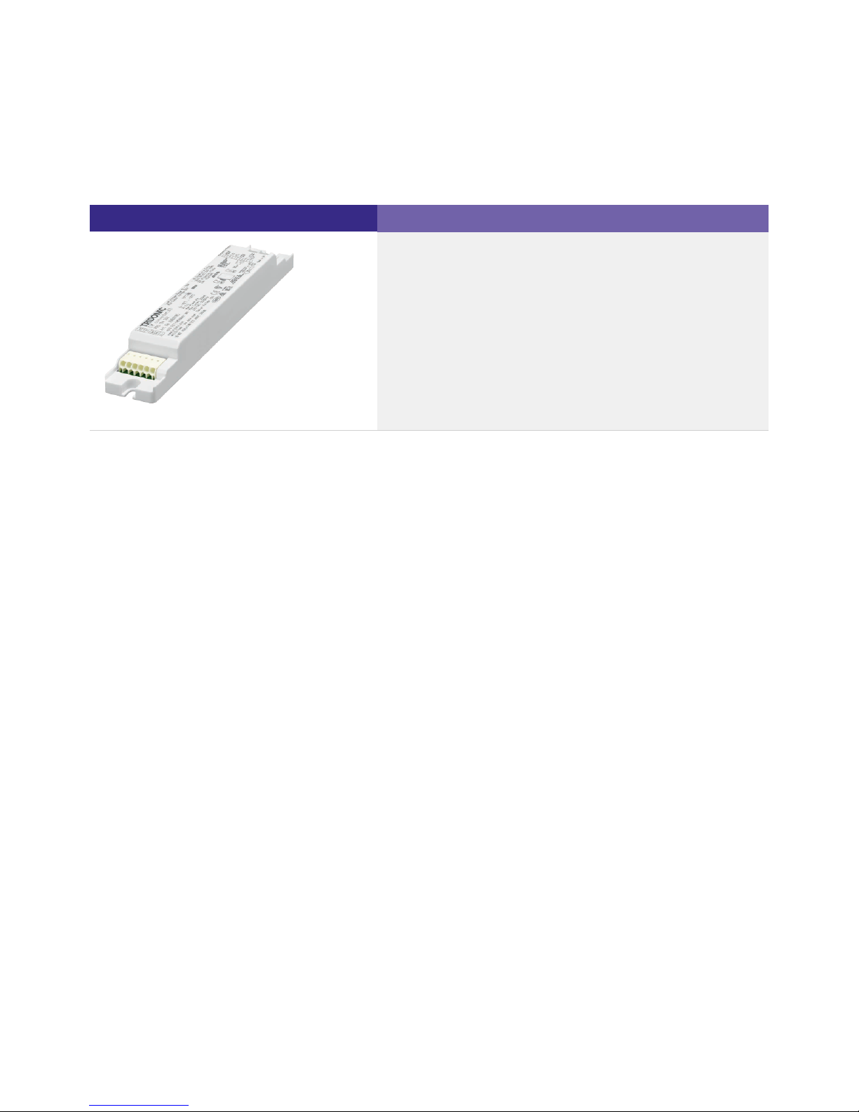
The EM converterLED ST is available in a low profile housing (21mm).
Image Description
Housing variant compact
4.2. Forward voltage
The EM converterLED ST is available with three different forward voltages: 10-52 V, 40-97 V, 50-200 V
...
Compact shape_
For installations inside the luminaire_
Typical area of application: Spotlights, downlights_
Dimensions: 179 × 30 × 21 mm_

Product manual EM converterLED ST | 08-2018 | 1.0 | en
Functions in emergency operation
c9 / 38
Overview of the main functions in emergency operation:
Area Function
Test function, p. 19 Automatic function and duration test Test activation via
selftest
Function test (interval) weekly
Duration test (interval) annual
Rated duration Adjustable to 1 or 2 hours
Status display Via two-colour indicator LED, p. 17
Battery charge system Intelligent multilevel charging system, p. 13
Intermittent charging (pulse charging) for NiMH
batteries
Adjustment of output current, p. 10 Automatic adjustment by device
Commissioning Automatic
Rest mode, Inhibit mode and Relight command, p.
14
Activation Activation via DC pulse
...

Product manual EM converterLED ST | 08-2018 | 1.0 | en
Functions in emergency operation
c10 / 38
5.1. Adjustable output current
5.1.1. Description
If the EM converterLED ST switches to emergency operation in case of a power failure, the device will detect the forward voltage of
the connected LED modules and set the correct LED current. Setting a constant output power ensures maximum light output in
emergency mode for the specified operating time.
An EM converterLED ST with approx. 3, 4 or 5 watts output power operates the connected LED modules with the output power
mentioned before. For this purpose, the device detects the connected LED forward voltage, and adjusts the LED forward current to
the appropriate value, resulting in an output power of approx. 3, 4 or 5 watts.
...
INOTICE
At the lowest range of permissible forward voltage, the efficiency may be slightly lower. In this case the output power is also
slightly lower.

Product manual EM converterLED ST | 08-2018 | 1.0 | en
Functions in emergency operation
c11 / 38
5.1.2. Calculation
Formel: P = U * I
P= U * I
Emergency output power:
Given by the EM converterLED ST
type
LED forward voltage:
Detected by the EM converterLED
ST
LED forward current:
Automatically adjusted by the EM
STconverterLED
Example
Given:
Wanted:
Result:
Different battery cell numbers offer flexibility in the available emergency output power - 2, 3, 4 and 5 cells for LED modules from 10 V
to 250 V forward voltage.
The LED current in emergency mode is automatically adjusted by the ST based on the total forward voltage of theEM converterLED
LED modules connected and the associated battery.
Control gear
Forward
voltage
range SELV Number of battery cells
EM converterLED ST 103 50V 10-52 V SELV < 60 V 3 cells for light output in emergency operation
EM converterLED ST 103 NiMH 50V 10-52 V SELV < 60 V 3 cells for light output in emergency operation
EM converterLED ST 104 50V 10-52 V SELV < 60 V 4 cells for light output in emergency operation
EM converterLED ST 104 50VNiMH 10-52 V SELV < 60 V 4 cells for light output in emergency operation
EM converterLED ST 134 NiCd 50V 10-52 V SELV < 60 V 4 cells for light output in emergency operation
EM converterLED ST 104 90V 40-97 V SELV < 120 V 4 cells for light output in emergency operation
EM converterLED ST 104 90VNiMH 40-97 V SELV < 120 V 4 cells for light output in emergency operation
LED forward voltage: 45 V (chosen as an example)_
LED forward current (at 45 V): 60 mA (taken from diagram ST 103)EM converterLED_
Emergency output power?_
Emergency output power:
P = U * I = 45 V * 60 mA = 2.7 W
_

Product manual EM converterLED ST | 08-2018 | 1.0 | en
Functions in emergency operation
c12 / 38
EM converterLED ST 105 90V 40-97 V SELV < 120 V 5 cells for light output in emergency operation
EM converterLED ST 105 90VNiMH 40-97 V SELV < 120 V 5 cells for light output in emergency operation
EM converterLED ST 135 90V 40-97 V SELV < 120 V 5 cells for light output in emergency operation
EM converterLED ST 104 50V 50-200 V no 4 cells for light output in emergency operation
EM converterLED ST 104 50VNiMH 50-200 V no 4 cells for light output in emergency operation
EM converterLED ST 105 50V 50-200 V no 5 cells for light output in emergency operation
EM converterLED ST 105 50VNiMH 50-200 V no 5 cells for light output in emergency operation
...
INOTICE
There is a separate chapter that describes how the light output in emergency operation can be determined (see Determining light
).output in emergency operation, p. 24

Product manual EM converterLED ST | 08-2018 | 1.0 | en
Functions in emergency operation
c13 / 38
5.2. Intelligent multilevel charging system
The multilevel charging system is used for minimising charging times while maximising battery life. During normal functional mains
operation the module charges the batteries using a specially developed charging algorithm.
When the permanent power supply is switched on for the first time the EM converterLED ST starts to charge the batteries for 20
hours in fast charge mode. This 20-hour preparatory charge ensures that the new batteries are completely charged before being used.
The 20-hour recharge is also used if a new battery is connected or if the device leaves the Rest mode (see Rest mode, Inhibit mode
).and Relight command, p. 14
At the end of the 20-hour charge the module automatically switches to trickle charge mode. This ensures that the batteries remain at
optimum charge levels and avoids any overheating due to overcharging.
After a power outage and subsequent emergency mode the EM converterLED ST recharges the batteries in fast charge mode.
However, the charge time is set so that only the power consumed during emergency mode is replaced. If emergency mode did not last
as long as the prescribed operating time the charging time will be reduced. If emergency mode extended for the full operating time
the charging time will be 10 hours for modules with an operating time of 1 hour, and 15 hours for modules with an operating time of 2
and 3 hours. Once the batteries are fully charged again the module automatically switches to trickle charge mode.
In trickle charge mode the battery status is continually monitored to ensure that the charging currents and battery voltages remain
within the specified limits. The status LED also shows such faults locally.
If a duration test is required while the battery is not yet fully charged the test will be postponed until charging is complete. This
prevents a duration test from being carried out with a battery that is not fully charged.
If the power supply fails during rapid charging the module will power the lamp immediately in emergency mode for as long as the
charge in the batteries will allow.
Initial charge mode:
20 hours of high charging current at the start to prepare the new battery cells and fully charge them.
_
Trickle charge mode:
Continuous low charge to maintain battery output and reduce battery temperature.
_
Fast charge mode:
Automatic adjustment of the charge time ensures minimal overcharging:
_
10 or 15 hours of rapid charge after a full discharge._
Shorter charge time after only a partial discharge._
NiCd batteries are charged with a constant charging current in trickle charge mode_
Special NiMH devices charge with a pulsed charging current in trickle charge mode_
INOTICE
A partially charged battery is defined as one for which the charger is operating in fast charge mode.
A fully charged battery is defined as one for which the charger is operating in trickle charge mode.

Product manual EM converterLED ST | 08-2018 | 1.0 | en
Functions in emergency operation
c14 / 38
5.3. Rest mode, Inhibit mode and Relight command
Emergency operation is automatically started when the mains supply is switched off. If the Rest mode is activated, the discharging of
the battery will be minimized by switching off the LED output.
Rest mode can be used during short periods of time when a building is completely unoccupied and the mains supply is to be switched
off intentionally, for example during a holiday period. Using Rest mode prevents a full discharge and possible damages to the
batteries during these times.
Rest mode has to be activated by a competent person. Activation is only possible after the mains supply has been switched off.
Contrary to this, if the Inhibit mode has been activated in advance, Rest mode will be automatically switched on if the mains supply is
switched off.
By sending the Relight command both modes, Rest mode and Inhibit mode, will be deactivated. The emergency unit will switch back
to the previous operating mode. If it has been in Rest mode, it will switch back to emergency mode, if it has been in Inhibit mode, it will
switch back to charging mode.
For all the different changes, activating Rest mode and Inhibit mode and sending the Relight command, DC voltage pulses of different
lengths are used. The table at gives an overview of all the operating modes.Switching between operating modes, p. 16
5.3.1. Activate Rest mode
Rest mode is activated as follows:
5.3.2. Deactivate Rest mode via Relight command
By sending the Relight command the Rest mode is deactivated. The emergency unit will switch back to emergency mode.
To deactivate Rest mode via Relight command, proceed as follows:
½CAUTION!
Even in Rest mode there is self discharge current and an extremely small level of discharge current flowing from the batteries. If the
batteries remain in Rest mode for prolonged periods of time this can lead to deep discharge and potential damage. Further
information can be found in the data sheet of the batteries (see ).Reference list, p. 38
Disconnect power supply_
Apply DC voltage pulse at the two terminal points "REST/L" and "REST/N"_
The signal ofmust have an amplitude 9.5 - 22.5 V with a pulse length of 150 - 1,000 ms_
The polarity of the voltage pulse does not matter_
INOTICE
Rest mode cannot be activated as long as the power supply hasn't been disconnected.
The maximum number of emergency units on one bus is 100 pieces with a maximum recommended cable length of 1,000 metres.
Rest mode voltage can be applied across all emergency modules (parallel connection).

Product manual EM converterLED ST | 08-2018 | 1.0 | en
Functions in emergency operation
c15 / 38
5.3.3. Activate Inhibit mode
Inhibit mode is activated as follows:
For further information see .Indicator LED, p. 17
5.3.4. Automatically switch from Inhibit mode to Rest mode
The emergency unit automatically switches from Inhibit mode to Rest mode if the following conditions are met:
5.3.5. Automatically deactivate Inhibit mode
Inhibit mode is automatically deactivated and the emergency unit switches back to charging mode if the following conditions are met:
5.3.6. Deactivate Inhibit mode via Relight command
By sending the Relight command the Inhibit mode is deactivated. The emergency unit will switch back to charging mode.
To deactivate Inhibit mode via Relight command, proceed as follows:
Apply DC voltage pulse at the two terminal points "REST/L" and "REST/N"_
The signal ofmust have an amplitude 9.5 - 22.5 V with a pulse length of 1,001 - 2,000 ms_
The polarity of the voltage pulse does not matter_
INOTICE
Reapplying the power supply does also deactivate Rest mode. In this case, the device switches from Rest mode to charge mode.
Make sure that the mains supply is switched on_
Apply DC voltage pulse at the two terminal points "REST/L" and "REST/N"
-> Emergency unit switches to Inhibit mode
-> Inhibit mode is active for a duration of 15 minutes
-> Inhibit mode is indicated by indicator LED (double pulsing GREEN)
_
The signal ofmust have an amplitude 9.5 - 22.5 V with a pulse length of 150 - 1,000 ms_
The polarity of the voltage pulse does not matter_
INOTICE
The inhibit mode must be activated before the mains supply is switched off.
Inhibit mode has been activated -and-_
Within 15 minutes after activation, the mains supply is switched off_
Within 15 minutes after activation, the mains supply is switched offnot_

Product manual EM converterLED ST | 08-2018 | 1.0 | en
Functions in emergency operation
c16 / 38
5.3.7. Switching between operating modes
The device has four different operating modes (Standby/Charge mode, Emergency mode, Rest mode and Inhibit mode). Depending on
the initial mode and the length of the applied DC voltage pulse the device switches between these operating modes. The following
table gives an overview:
Applied pulse
length Charging mode Emergency mode Rest mode Inhibit mode
150 - 1,000 ms Switches to Inhibit
mode
Switches to Rest
mode
- -
1,001 - 2,000 ms
(Relight command)
- - Switches to Emergency
mode
Switches to charging
mode
...
Apply DC voltage pulse at the two terminal points "REST/L" and "REST/N"_
The signal ofmust have an amplitude 9.5 - 22.5 V with a pulse length of 1,001 - 2,000 ms_
The polarity of the voltage pulse does not matter_

Product manual EM converterLED ST | 08-2018 | 1.0 | en
Functions in emergency operation
c17 / 38
5.4. Indicator LED
System status is locally indicated by a bi-colour indicator LED.
LED indication Status Description
Permanent GREEN Standby, System OK Mains operation, battery is charged
Fast flashing GREEN
(0,1 s on - 0,1 s off)
Function test underway
Slow flashing GREEN
(1 s on - 1 s off)
Duration test underway
Double pulsing
GREEN
Inhibit mode is
activated
The Inhibit mode makes it possible to set the emergency mode to "inhibited"; in this
mode, the power can be turned off without switching to emergency mode.
The Inhibit mode is activated by sending the inhibit signal, while the modules are still
connected to mains. Just as in Rest mode, the device supports the Relight functions.
After a break of 15 minutes, the inhibit mode is automatically reset.
Permanent RED Lamp failure Open circuit -or- Short circuit -or- LED failure
Fast flashing RED
(0,1 s on - 0,1 s off)
Charging failure Incorrect charging current
INOTICE
After an exchange of the LED module, the indicator LED remains permanent
RED. The lamp failure indication remains set until a function test has been
successfully completed (automatically with the weekly function test or
immediately by briefly interrupting the power supply or by manually starting
the function test with a test switch (see )).Starting the function test, p. 23
The LED module's mains operation does not reset the lamp failure indication.
INOTICE
While the battery is in trickle charge mode and the mains supply is connected,
the micro controller in the emergency unit monitors the charging parameters. If
an error is detected or a parameter is out of tolerance, the indicator LED
switches to fast flashing RED. If the error has been corrected, the indicator LED
immediately switches back to GREEN and continues the charging operation of
the battery.

Product manual EM converterLED ST | 08-2018 | 1.0 | en
Functions in emergency operation
c18 / 38
Slow flashing RED
(1 s on - 1 s off)
Battery failure Battery failed duration test or function test -or- Battery is defect -or- Incorrect
battery voltage
GREEN and RED off Battery operation Emergency mode: Mains disconnected -or- mains failure
...
INOTICE
Battery failed duration test or function test:
If the battery does not reach full operating time, the indicator LED is slow
flashing RED.
After an exchange of the battery the indicator LED switches to GREEN. To
guarantee a satisfactory operating time, the battery is then charged for 20
hours and a second duration test is carried out.
INOTICE
Battery is defect or incorrect battery voltage:
While the battery is in trickle charge mode and the mains supply is connected,
the micro controller in the emergency unit monitors the condition of the
battery. If an error is detected , the indicator LED switches to RED. If the error
has been corrected, the indicator LED immediately switches back to GREEN
and continues the charging operation of the battery.
Product manual EM converterLED ST | 08-2018 | 1.0 | en
Settings for emergency tests
c19 / 38
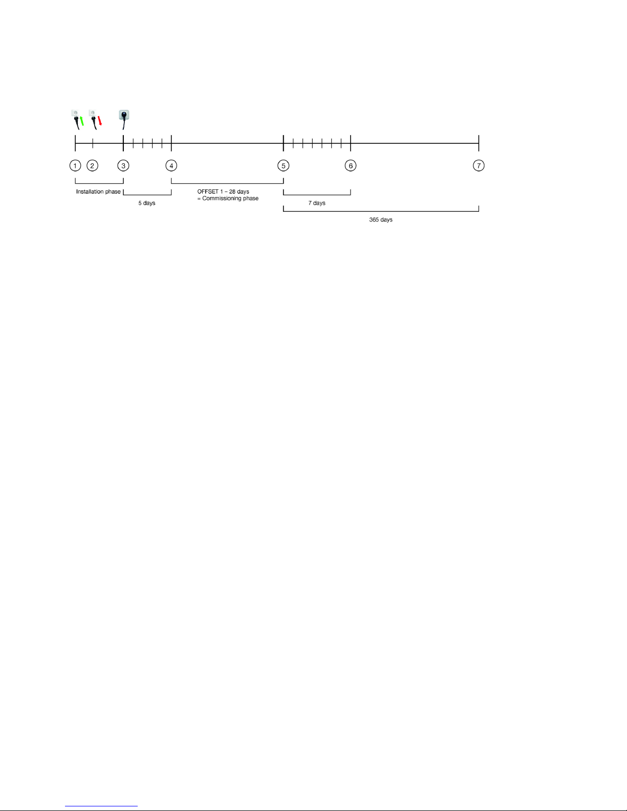
Annotation:
(1) First connection to the power supply
(2) Phase, in which the power supply is switched on and off (possibly numerous times)
(3) Phase, in which the power supply is "permanently" connected (no interruption for at least 5 days)
(4) Delaying the commissioning test for 1-28 day
(5) Commissioning test begins
(6) First function test
(7) First duration test
...

Product manual EM converterLED ST | 08-2018 | 1.0 | en
Settings for emergency tests
c20 / 38
6.1. Test times and test intervals
Devices of the EM converterLED ST series are tested via selftest function. The following table gives an overview of the parameters:
Test trigger Test times Test intervals
Test
triggered by
emergency
lighting unit
There are two variants for setting the test time. In some cases different rules apply for the
setting of the day and the time:
To prevent that the emergency lighting tests of all luminaires are carried out at the same time,
each luminaire has a pre-programmed code which delays the test time for a specified time (see
).Commissioning test, p. 20
Test time intervals
between the tests
are fixed:
6.2. Commissioning test
The commissioning test is a first duration test. The relevant standard (IEC 62034: Automatic test systems for battery powered
emergency escape lighting) requires that such a test is carried out after the installation.
The commissioning test is often made more difficult because the power supply is switched on and off during the installation phase.
This is the case, for example, if the site is powered off at night for security reasons. To address this problem, the EM converterLED ST
monitors the power supply and will only start with the commissioning test if the power supply hasn't been interrupted for 5 days.
To prevent that all the luminaires perform the emergency test at the same time, each luminaire has a pre-programmed code with a
value of 1-28, which delays the test time of that luminaire for a specified time.
28 days after the start of the commissioning all devices will have completed the required commissioning test.
The day of the commissioning test serves as a reference point for all further function and duration tests (see Test times and test
Automatic setting of the function test:
The time of the function test is the same as the time when the device was first
connected to the power supply (see (1) in above diagram), the day of the function test
is the same as the day when the commissioning test was carried out (see (5) in above
diagram and ).Commissioning test, p. 20
_
Automatic setting of the duration test:
The time of the duration test is set by the , the day of theAdaptive test mode, p. 22
duration test is the same as the day when the commissioning test was carried out (see
(5) in above diagram and ). Commissioning test, p. 20
_
Manual setting of the test time and the test day for a single luminaire via test switch
(see ).Setting the test time for one luminaire, p. 23
_
Manual setting of the test time and the test day for all the luminaires in an emergency
lighting circuit by switching the power supply on and off (see Setting the test time for
).all the luminaires in an emergency lighting circuit, p. 23
_
Function test:
weekly
_
Duration test:
annual
_
Devices with code 1 will be tested one day after the completion of the 5 day long monitoring of the power supply (that is 6
days after the uninterrupted connection to the supply).
_
Devices with code 2 will be tested two days after the completion of the 5 day long monitoring of the power supply (that is 7
days after the uninterrupted connection to the supply).
_
Devices with higher code numbers will be tested with a delay that corresponds to that code number._
Table of contents
Other Tridonic Lighting Equipment manuals

Tridonic
Tridonic EM powerLED ST FX User manual

Tridonic
Tridonic Excite Series User manual

Tridonic
Tridonic LCA PRE OTD User manual

Tridonic
Tridonic Excite Series User manual

Tridonic
Tridonic EM ready2apply SELFTEST 2 W SM User manual

Tridonic
Tridonic Essence LC 35W 200-350mA stepDIM lp SNC User manual

Tridonic
Tridonic PRO Series User manual

Tridonic
Tridonic Excite Series User manual

Tridonic
Tridonic PRO Series User manual

Tridonic
Tridonic EM converterLED ST MH/LiFePO4 50 V User manual


