Tridonic DALI RM CDM 30 10A 1CH User manual

www.tridonic.com 1
Subject to change without notice. Information provided without guarantee.
Data sheet 04/21-CO137-1
Lighting Controls and Connectivity
DALI-2 components
Product description
• DALI-2 Relay
• Compatible with DALI and DALI-2 versions
• Compliant to EN 62386-208
• 1 channel actuator (switch) with DALI-2 input
• Protected against DALI over voltage
• Suitable for switchboard mount on standard DIN rail
• Mains rated dry-contact (volt-free) potential free relay output
• Compliant DALI device type 7
• Small dimensions
• 5 years guarantee (conditions at www.tridonic.com)
Interfaces
• DALI
Functions
• Optimized for electronic loads with high in-rush currents like
LED Drivers, which have short but very high peaks of in-rush
currents
• Switching of loads with inrush currents up to 490 A / 1.5 ms
• Compliant with common DALI-2 controllers and gateways
• DALI backwards compatible
È
Standards, page 3
Wiring diagrams and installation examples, page 4
DALI RM CDM 30 10A 1CH
DALI-2 single channel relay
www.tridonic.com 2
Subject to change without notice. Information provided without guarantee.
Data sheet 04/21-CO137-1
Lighting Controls and Connectivity
DALI-2 components
Technical data
Rated supply voltage 220 – 240 V
Mains frequency 50 / 60 Hz
Current consumption of DALI 2 mA
Input DALI
Output Potential free contact
Relay type non-latching, normally open
Output load (resistive / inductive) 10 A / 6 A
In-rush current (peak / duration) 490 A / 1.5 ms
Relay switching cycles150,000
Ambient temperature ta -20 ... +45 °C
Storage temperature ts -20 ... +65 °C
Humidity 20 ... 90 % (non-condensing)
Starting time ≤ 0.3 s
Type of protection IP20
Protection class Protection class II
Mounting DIN rail mounting, 35 mm
Housing material Polycarbonat
Housing colour White (RAL 9003)
Guarantee (conditions at www.tridonic.com) 5 years
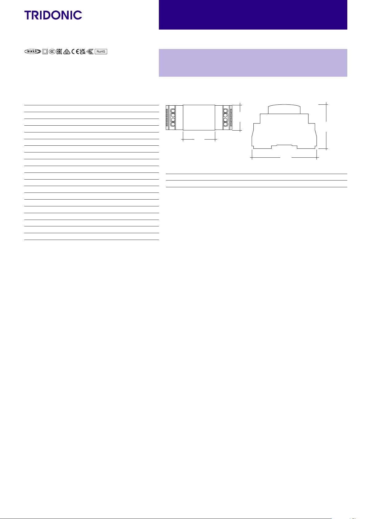
Dimension L x W x H 92.5 x 36 x 62 mm
DALI RM CDM 30 10A 1CH
DALI-2 single channel relay
36
62
45
92,5
Ordering data
Type Article number Packaging, carton Weight per pc.
DALI RM CDM 30 10A 1CH 28003311 40 pc(s). 0.088 kg
1Max. switch cycles per hour are 360. One cycle is either close or open.

www.tridonic.com 3
Subject to change without notice. Information provided without guarantee.
Data sheet 04/21-CO137-1
Lighting Controls and Connectivity
DALI-2 components
1. Standards
EN 55015
EN 60669-2-1
EN 61000-3-2
EN 61000-3-3
EN 62386-208
EN 62386-101 Ed.2
EN 62386-102 Ed.2
3. Installation
3.1 Safety instructions
• Do not connect the device to DC (direct current) voltage, as this will
damage the device.
• Do not create a short circuit on the secondary side, as this will damage the
device.
It is recommended to connect the device with a residual current circuit
breaker (RCD) or a circuit breaker with a rated value not higher than
10 A to the secondary side to protect the device in case of a
short circuit.
• Installation of this device may only be carried out by specialist staff who
have provided proof of their skills.
• The power supply must be switched off before handling the device.
• The relevant safety and accident prevention regulations must be observed.
• DALI signals are not SELV. Therefore the same procedures should be
applied as working with mains voltage.
1.2 Glow wire test
according to EN 61347-2-11 passed for temperatures up to 750°C.
2. Common
• Loads that do not have a DALI input can be integrated in the DALI circuit.
The loads can be switched on and o via DALI.
3.2 Area of application
The device may only:
• be used for the applications specified,
• for safe installation in dry, clean environment and
• be installed in such a way that access is only possible using a tool.

www.tridonic.com 4
Subject to change without notice. Information provided without guarantee.
Data sheet 04/21-CO137-1
Lighting Controls and Connectivity
DALI-2 components
6 – 7 mm
wire preparation:
1 – 4 mm²
3.5 Wiring type and cross section
The wiring can be solid wire or stranded wire with end sleeve with a
cross-section of 1 to 4 mm².
3.6 Note for Application Controller
Device is developed according DALI Standard EN 62386-208 and
is DALI device Type 7, control gear – Switching function.
4. Miscellaneous
4.2 Additional information
Additional technical information at www.tridonic.com →Technical Data
Lifetime declarations are informative and represent no warranty claim.
No warranty if device was opened.
4.1 Disposal of equipment
Return old devices in accordance with the WEEE directive to suitable
recycling facilities.
3.3 Connection diagrams
DALI RM
CDM 30
10A 1CH
L
N
Load
Lout
Lin
10 A
MSensor G3
DALI
PS
L
N
LED DriverLED Driver
DALI-2 Application Controller
DALI
RM
CDM
DA
DA
T4
T3
T2
T1
COM
DA
DA
3.4 Installation
Mount the DALI relay on DIN rail inside a mains rated enclosure as shown in
fig. 1.
To remove from DIN rail, release the clip mechanism with a flat blade screw
driver, as per fig. 2.
Fig. 1 Fig. 2
Popular Relay manuals by other brands


Siemens
Siemens SIRIUS 3RS1000 operating instructions

Viessmann
Viessmann 5551 Operation manual

Siemens
Siemens SIRIUS 3SK2112 AA10 Series Original operating instructions

ELMON
ELMON Vario 01-27 operating manual

Veris Industries
Veris Industries Hawkeye 735 installation guide

WAGO
WAGO I/O-SYSTEM 750-517 manual