TRIGEM FLORIDA-TG Technical manual

Hardware Document
RPR404-IB1 Product Engineering Team
TriGem Computer Inc. 1 / 17 Revision 1.1
TriGem Micro-ATX Motherboard (FLORIDA-TG(A))
Hardware Document
April, 22 2000
Revision 1.1

Hardware Document
RPR404-IB1 Product Engineering Team
TriGem Computer Inc. 2 / 17 Revision 1.1
Document Revision History
Released date Revision Description
February, 1 1999 Rev. 0.9 First released version for this document.
This document describes the major specification of the Florida
motherboard and the functional feature to be extended by the customer.
The motherboard revision number is DP1
March, 5 1999 Rev. 1.0
April, 22 2000 Rev. 1.1 Audio Chipset is changed. (CS4280ÆCS4281)
Form a new model Florida-TG(A)
Marketing Information
Address 45-2 Yoidodong, Youngdeungpoku, Seoul, Korea
Telephone 82-2-3774-4303 (Ext. International Business Team)
Fax 82-2-786-9478
Email dcchang@trigem.co.kr (Dong Chun Chang)
Technical Support
Address 1055 Shingil-Dong, Ansan, Kyunggi-Do, Korea
Telephone 82-345-491-9528 (Ext. 606)
Fax 82-345-593-6721
User’s Notice
No part of this product, including the schematics and BIOS may be reproduced, transmitted,
transcribed, stored in a retrieval system, or translated into any language in any form by any means
without the express written permission of TriGem Computer Inc. except the document kept by the
purchaser for backup purposes.
© Copyright 1999 TriGem Computer Inc. All rights reserved

Hardware Document
RPR404-IB1 Product Engineering Team
TriGem Computer Inc. 3 / 17 Revision 1.1
Contents of Table
I. Introduction
1. Generation Description ------------------------------------------------------------ 4
2. Function Block Diagram ------------------------------------------------------------ 6
II. System Overview
1. Major Units ----------------------------------------------------------------------------- 7
2. Upgradeability ------------------------------------------------------------------------- 8
2-1. Processor -------------------------------------------------------------------------- 8
2-2. Memory ----------------------------------------------------------------------------- 8
2-3. BIOS --------------------------------------------------------------------------------- 9
2-4. Expansion Slot -------------------------------------------------------------------- 9
2-5. Advanced Configuration and Power Interface (ACPI) ------------------- 10
2-6. Manufacturing Options ---------------------------------------------------------- 10
III. Jumper & Connector Description
1. Motherboard Jumper Setting ------------------------------------------------------ 11
1-1. Selection for Processor CPU Clock ------------------------------------------ 11
1-2. Other functionality --------------------------------------------------------------- 11
1-3. AGP graphics device function ------------------------------------------------- 12
1-4. OEM/ODM selector -------------------------------------------------------------- 12
2.Motherboard Connector Description --------------------------------------------- 14
2-1.Motherboard Internal Connector --------------------------------------------- 14
2-2.Motherboard External I/O Port ------------------------------------------------ 16
3.Joystick & USB daughter board --------------------------------------------------- 16

Hardware Document
RPR404-IB1 Product Engineering Team
TriGem Computer Inc. 4 / 17 Revision 1.1
I. Introduction
The Florida-TG Micro ATX motherboard offers a time to market consumer and corporate desktop
solution featuring the Intel Celeron PPGA processor with 66MHz front side bus and the Intel 440LX AGP sets in a
Micro ATX low profile motherboards. In addition, the integrated graphics components have been upgraded with the
AGP graphics controller and 4 or 8MB of SGRAM.
The Florida-TG motherboard was designed to be highly minimized system cost. In this effort a smaller
form factor, Micro-ATX, gives the greater space economy and more affordable systems. Integrating AGP graphics
controller and SGRAM, as well as PCI audio solution with AC97 Codec onto the motherboard eliminates the need
for more expensive graphic and audio add-in cards. The end result is a system platform with a primary component
level of integration with translates into affordable solution for entry-level users.
1. General description
TMotherboard
•Small PCB size in the Micro ATX form factor (ATX V1.2 form factor)
•227mm * 244mm * 1.6t (4 Layers)
TProcessor
•Intel Socket-370 (370pin PPGA Socket)
•Intel Celeron 300A/333/366/400/433/466/500/533MHz processor support
TMain Chipset
•AGPsets PCI/AGP Controller : Intel 440LX
•PCI bus mastering controller, and Power management interface : Intel PIIX4e
•Graphics : ATi RAGE Pro Turbo with 4 or 8 MB SGRAM
•Audio : Crystal CS4281 with Ac97 Codec(CS4297A)
•Super I/O : IT8673F-A
•DC-DC Converter : SC1164
•Clock : ICS9148BF (66MHz host clock support)
TMemory Configuration
•System Memory
- Two banks of 3.3V EDO/SDRAM (168pin unbuffered DIMM) with max 256MB
- EDO/SDRAM operation in 66MHz front side bus
•Flash Memory : Programmable 2MB Flash memory
TI/O Feature
•Integrated standard I/O functions in the rear side
- One multi-mode parallel port
- One FIFO serial ports and optional port by header type
- PS/2 styles keyboard and mouse port
- One USB port
- Three audio jack for Line input, Speaker output and MIC input
•Integrated standard I/O functions in the front side
- One Joystick port
- One USB port
TAudio Subsystem
•Crystal CS4281 PCI audio controller with fully DOS Games compatibility via PC/PCI, DDMA support
•Compatible with sound blaster, sound blaster pro, and window sound system
•Enhanced Stereo full duplex operation
•Advanced MPC3-compatible input and output mixer
•Joystick port and MPU-401 compatible MIDI interface
•PC97 and PC98 compliance (and compliance with preliminary PC99)

Hardware Document
RPR404-IB1 Product Engineering Team
TriGem Computer Inc. 5 / 17 Revision 1.1
TGraphics Subsystem
•General features
- First graphics accelerator to support AGP 2X mode with Sideband Addressing and AGP Texturing
(Execute mode) to realize all the benefits of AGP
- Superior 3D performance achieved through a floating point setup engine rated at 1.2 million
triangles/sec
- 100MHz SGRAM support for maximum 2D and 3D performance
- Integrated 230MHz DAC allows 85Hz refresh at 1600x1200 resolutions
- Flexible graphics memory configuration : 4MB or 8MB SGRAM(Manufacture option)
- Integrates superior video features, including filtered scaling of 720 pixel DVD content and MPEG-2
motion compensation for software DVD
- Highly integrated 64 bit graphics accelerator with superior support for 3D and motion video, making
it ideal for multimedia PCs
- Ati Rage Pro Turbo delivers superior 3D acceleration and comprehensive 3D support including
support for true color (32bpp) rendering, a triangle set-up engine, single-pass tri-linear filtering, six
perspectively correct texturing modes, video texturing.
•3D Acceleration
- Hidden surface removal using 16-bit z-buffering
- Full support for Direct3D texture lighting
- Dithering support in 16bpp for near 24bpp quality in less memory
Hardware Document
RPR404-IB1 Product Engineering Team
TriGem Computer Inc. 6 / 17 Revision 1.1
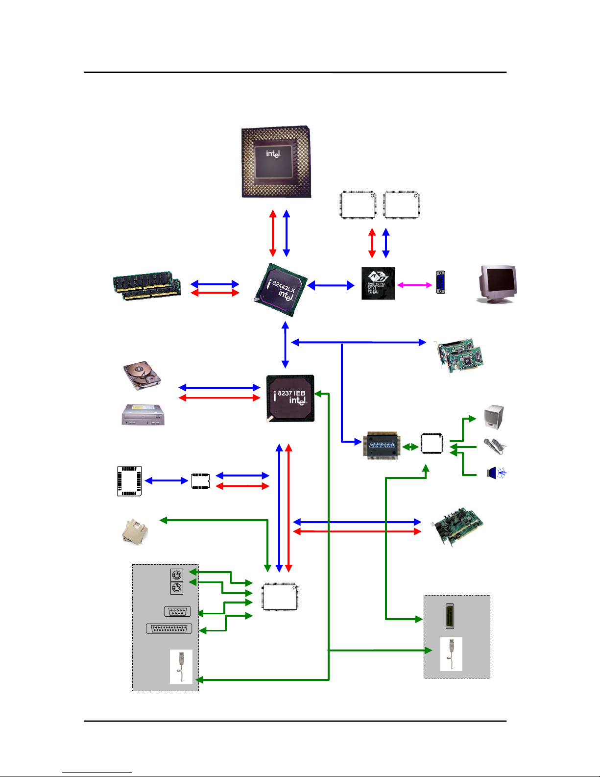
2. Function Block Diagram
DIMM Modules
Video
BIOS
XD SD
SA
Speaker
MIC
Line in
GMAGMD
ATi RAGE
Pro Turbo
RGB
AD
Intel Celeron
PGA 370
MD
MA
HAHD
GAD
[ Real Side
Port ]
HDD
CDROM
HD Data
HA Address
PIIX4e
SD
SA
PCI Slot
ISA Slots
USB
Joystick
Keyboard
Mouse
Serial
Parallel
USB
I/O
IT8673F
CS4281
2M 2M
SGRAM
Codec
CS4297A

Hardware Document
RPR404-IB1 Product Engineering Team
TriGem Computer Inc. 7 / 17 Revision 1.1
II. System Overview
1. Major Units
Sound Chip
CS4281-CM
Intel
82371EB
PIIX4e
AGP Graphic
ATi Rage Pro
Turbo
Battery(3V)
Flash ROM
2MB (System+Video)
PGA 370
Intel
82443LX
Clock
ICS9148BF
2 DIMM
Sockets
AC97 Codec
CS4297A
Super I/O
IT8673F-A
Regurater
SC1164
Video Memory
4 or 8 MB SGRAM
Hardware Document
RPR404-IB1 Product Engineering Team
TriGem Computer Inc. 8 / 17 Revision 1.1
2. Upgradeability
2-1. Processor
FLORIDA-TG motherboard provides the 370pin PGA370 socket that is not backward compatible with ZIF
socket-7 processors The Processor’s VID pin automatically program the voltage regulator on the motherboard
to the required processor voltage. The motherboard supports processors that run internally at
300/333/366/400 MHz.
TSupported Intel Celeron Processors (PPGA Socket Type)
•Intel : Celeron 300MHz
: Celeron 333MHz
: Celeron 366MHz
: Celeron 400MHz
: Celeron 433MHz
: Celeron 466MHz
: Celeron 500MHz
: Celeron 533MHz
2-2. Memory
The motherboard has two, dual inline memory module (DIMM), minimum 16MB to maximum 256MB memory
size. The BIOS can automatically detect the memory type, size, and speed through SMBUS interface between
the core chipset and DIMM module.
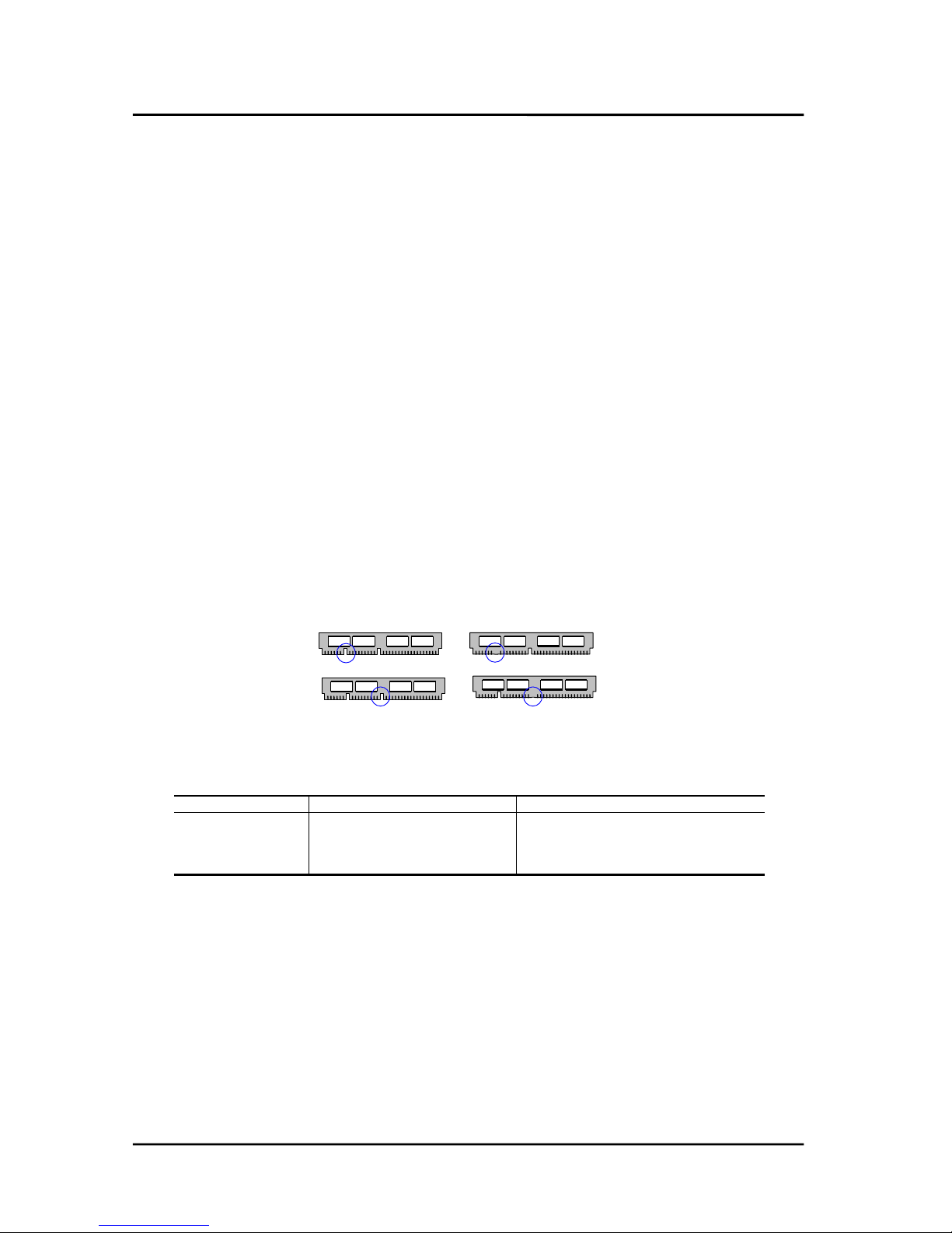
The motherboard supports the following memory features
•3.3V and unbuffered168-pin DIMM
Voltage detection
3.3V Version 5V Version
Unbuffered detection
Unbuffered Buffered
•66MHz and 100MHz unbuffered SDRAM, and also EDO DRAM
•Non-ECC memory and ECC memory support
•Single or double-sided DIMM with the following types
DIMM size Non-ECC memory ECC memory
16MB 2Mbit * 64bit 2Mbit * 72bit
32MB 4Mbit * 64bit 4Mbit * 72bit
64MB 8Mbit * 64bit 8Mbit * 72bit
128MB 16Mbit * 64bit 16Mbit * 72bit
Hardware Document
RPR404-IB1 Product Engineering Team
TriGem Computer Inc. 9 / 17 Revision 1.1
2-3 BIOS
The motherboard uses a TriGem-AMI BIOS, which is stored in flash memory and can be upgraded using a disk-
based program. A new version of the BIOS can be upgraded from a diskette using the Flash Memory Update
utility.
TFlash memory organization
Address (Hex) Size Functional description
FFFF0000 - FFFFFFFF 64KB Boot block
FFFA0000 - FFFEFFFF 256KB Main BIOS block
FF9F0000 - FFF9FFFF 8KB Used by BIOS (Event logging)
FFF9E000 - FFF9EFFF 8KB OEM logo or can flash area
FFF9C000 - FFF9DFFF 16KB DMI configuration data, PnP,
FFF90000 - FFF9BFFF 96KB Fault tolerant storage
FFF80000 - FFF8FFFF 64KB Fault tolerant backup block
TOn-board device management
The BIOS can manage the devices on the motherboard over the CMOS setup menu. However the
corresponding jumper as described Jumper setting section later can disable the built-in AGP graphics
controller.
Device Description CMOS setup menu Default value
Internal Cache Celeron PPGA Processor Enable / Disable Enabled
PS/2 Mouse Intel 82371EB (PIIX4e) Enable / Disable Enabled
USB Function Intel 82371EB (PIIX4e) Enable / Disable Enabled
On board Sound CS4281 with CS4297A Codec Enable / Disable Enabled
On board FDC Super I/O (IT8673F-A) Auto / Enable / Disable Auto
On board serial Super I/O (IT8673F-A) Auto / 3F8 / 2F8 / 3E8 / 2E8 Auto
On board parallel Super I/O (IT8673F-A) Auto / Disable / 378 / 278 / 3BC Auto
On board IDE Intel 82371EB (PIIX4e) Disable / Primary / Secondary / Both Both
2-4. Expansion Slot
The motherboard support ISA, PCI and AGP function. ISA and PCI functions are extended to the additional slot
with two ISA and two PCI, and AGP function is designed in the motherboard with AGP graphics controller.
TPCI configuration space map
Bus number Device number Function number Device
00 00 00 Intel 82443LX
00 01 00 Intel 82371EB (PIIX4e)
00 07 00 PCI/ISA bridge (PIIX4e)
00 07 01 IDE bus master (PIIX4e)
00 07 02 USB (PIIX4e)
00 07 03 Power management (PIIX4e)
01 00 00 ATi Rage Pro Turbo graphic controller (AGP)
00 13 00 PCI slot1
00 12 00 PCI slot2

Hardware Document
RPR404-IB1 Product Engineering Team
TriGem Computer Inc. 10 / 17 Revision 1.1
TPCI interrupt & master number routing map
Intel 82371EB (PIIX4e) PCI/ISA bridge has four programmable interrupt request input signals. Any PCI interrupt
source connects to one of these interrupts signals and assigned to the free proper interrupt number by PnP
BIOS.
SB INT
signals
First
PCI slot
Second
PCI slot
AGP *1
graphics
PIIX4e
USB device
PIRQA INTA INTB INTA
PIRQB INTB INTC
PIRQC INTC INTD
PIRQD INTD INTA INTA
Master REQ0 REQ1
IDSEL AD30 AD29 AD18
Note 1.
Also AGP graphics controller does not use any PCI interrupt in the Florida-TG(A) motherboard, because
the interrupt function of AGP graphics controller was designed to disabled status. For more information,
please contact the technical support team.
2-5. Advanced Configuration and Power Interface (ACPI)
The motherboard and system BIOS support the ACPI that requires an ACPI-aware operating system such as
Windows-NT 5.0 or Windows 98. ACPI feature include
•Plug and play and APM functionality normally contained in the BIOS
•Power management control of individual devices : add-in cards, hard disk drives, USB devices, and
Video
•A soft-off feature that enables operating system to power off the computer
•Support for multiple wakeup events
•Indication LED for normal mode (Green), standby mode (Blinking Green), and suspend mode (Blinking
Green) but this function is dependent on the LED logic.
TWakeup devices and events
Wakeup device Wakeup events and functionality
Power switch Wakeup from Power-off status and power-off function
LAN Wakeup from power-off status
Modem Wakeup from power-off status
Sleep button Wakeup from power-off status and go to suspend mode (option)
2-6. Manufacturing Options
The motherboard has several manufacturing options according to OEM/ODM requirement. Make sure that
these options can be applied in the assembly stage, and it’s impossible to upgrade or change in the customer
field.
Option items Selectable functionality Feature changes
Joystick port Front side / Rear side Use additional board or not
USB port Front side / Rear side Use additional board or not
Super I/O IT8673F-A /ITE8693(Option) Include LM79(Option)
Graphics controller Rage Pro Turbo AGP mode (2x)
Graphics memory 4MB / 8MB(Option) Two SGRAM configuration

Hardware Document
RPR404-IB1 Product Engineering Team
TriGem Computer Inc. 11 / 17 Revision 1.1
III. Jumper & Connector Description
1. Motherboard Jumper Setting
1-1. Selection for Processor CPU Clock
Intel Celeron PPGA Processor is auto set the core to bus frequency ratio.
1-2. Other functionality
DIP Switch Function 2-3 1-2(Default)
J5 CMOS RAM function Clear CMOS RAM Enable write/save
J6 Password function Clear password Enable password
J7 CMOS setup function Disable to edit CMOS contents Enable to edit CMOS
contents
J8 FDD write protect Disable to write data
to Floppy disk
Enable to write data
to Floppy disk
J1
J5,J6,J7,J8
J2,J3,J4

Hardware Document
RPR404-IB1 Product Engineering Team
TriGem Computer Inc. 12 / 17 Revision 1.1
1-3. AGP graphics device function
This jumper does set the functionality of the built-in AGP graphics controller
J1 AGP device functionality
1-2 Disable AGP graphics controller built in the motherboard
2-3 (default) Enable AGP graphics controller built in the motherboard
1-4. OEM/ODM selector
These jumpers (J2, J3 & J4) will be optional parts for the OEM/ODM logo message selector.

Hardware Document
RPR404-IB1 Product Engineering Team
TriGem Computer Inc. 13 / 17 Revision 1.1
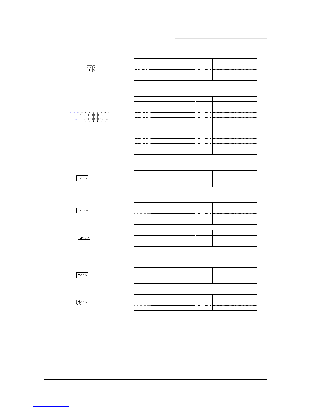
2. I/O Header Connector Description
2-1. Motherboard Internal Connector
TCPU FAN connector (CN54)
Pin number Signal description
1GND
2FANpower
3 Tachometer (speed)
TSystem Chassis FAN connector (CN53)
Pin number Signal description
1GND
2 FAN control
3 Tachometer (Speed)
1 2 3
CN54
1 2 3
UBS & Joystick
ISA Slot
PCI Slot
Modem Sound
DIMM Dodule
ATX PSU
Lan Wake up
Modem wake up Pri-IDE
Indicator HeaderAux.-Indicator
Sec-IDE
PC/PCI Header
Header(CN71&CON1)
(CN17,18)
CN12,13
CN46,70
CD Sound CN43,44
(CN3,4)
connector (CN7)
System Fan (CN53)
(CN5)
(CN51)
FDD connector
(CN9)
Connector(CN10)
(CN48)
Header (CN49)
Connector(CN11)
CPU Fan (CN54)
(CN23)
Video Sound CN45
Hardware Document
RPR404-IB1 Product Engineering Team
TriGem Computer Inc. 14 / 17 Revision 1.1
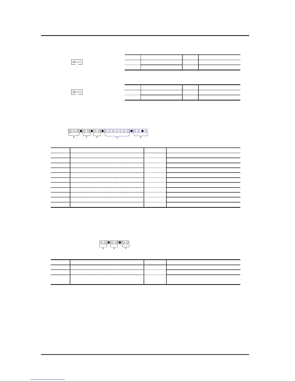
TPC/PCI connector (CN23)
Pin Signal description Pin Signal description
1/PCGNTA 4/PCREQA
2GND 5N.C
3Key 6SER_IRQ
TJoystick & USB connector (CON1, CN71)
Pin Signal description Pin Signal description
1VCC 9VCC
2 GD(4) 10 GD(6)
3GD(0) 11GD(2)
4 GND 12 MIDI OUT
5GND 13GD(3)
6 GD(1) 14 GD(7)
7 GD(5) 15 MIDI IN
8VCC 16Key
1 GND 3 Positive DATA
2 Negative DATA 4 VCC
TVideo Sound (CN45)
Pin Signal description Pin Signal description
1 Left Sound 3 GND
2 GND 4 Right Sound
TModem Sound (CN46, CN70)
Pin Signal description Pin Signal description
1MIC 4GND
2 GND 5 MONO IN
3 MONO OUT
Pin Signal description Pin Signal description
1 MONO IN 3 GND
2GND 4MIC
TCD Sound (CN43, CN44)
Pin Signal description Pin Signal description
1 Left Sound 3 GND
2 GND 4 Right Sound
Pin Signal description Pin Signal description
1GND 3GND
2 Left Sound 4 Right Sound
2 4 6
1 3 5
1 2 3 4
1 2 3 4
ATAPI CD (CN43)
1 2 3 4 5
CN46
1 2 3 4
CN70
1 2 3 4
Mitsumi CD (CN44)
3 1 8 7 6 5 4 3 2 1
4 2 16 15 14 13 12 11 10 9
Hardware Document
RPR404-IB1 Product Engineering Team
TriGem Computer Inc. 15 / 17 Revision 1.1
TLAN Wakeup (CN5)
Pin Signal description Pin Signal description
1 +5VSB 3 LANWK
2GND
TModem Wakeup (CN51)
Pin Signal description Pin Signal description
1 Modem Ring 3 +5VSB
2GND
TIndicator Header (CN48)
Pin Signal description Pin Signal description
1 VCC 12 GND (Option)
2 PM indicator signal 13 IRTX (Option)
3 GND 14 VCC (Option)
4 Key 15 IRSEL (Option)
5 VCC 16 N.C
6 HDD access signal 17 GND (Option)
7Key 18 Key(Option)
8 Power-ON switch signal 19 VCC (Option)
9 GND 20 GND (Option)
10 Key 21 N.C
11 IRRX (Option) 22 Speaker signal (Option)
TAux. Indicator Header (CN49) (Option)
Pin Signal description Pin Signal description
1 Key lock Signal to Super I/O 2 GND
3 Key 4 Reset signal
5GND 6 Key
7 Sleep Function signal 8 GND
1 2 3 4
1 2 3 4
PWR HDD DC SW IrDA Speaker
2
13 5 6 8 9 11 12 13 14 15 16 17 19 20 22
Sleep Reset Keylock
8 7 5 4 12
Hardware Document
RPR404-IB1 Product Engineering Team
TriGem Computer Inc. 16 / 17 Revision 1.1
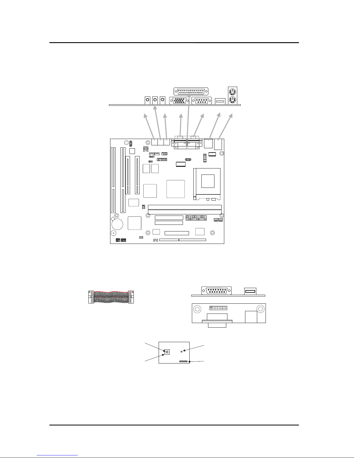
2-2. Motherboard External I/O Port
3. Joystick & USB daughter board
Joystick USB
20pin Flat Cable
4. LED & Power S/W board
Power LED color : Green (normal working)
Blinking Green (power management mode)
HDD LED color : Green light on (HDD access)
Light off (no access to HDD device)
Power LED
Power Switch
HDD Access
LED
LED board to board
connector
Parallel port
Video COM1 USB
Mouse
KeyboardSPKMIC
L-IN

Hardware Document
RPR404-IB1 Product Engineering Team
TriGem Computer Inc. 17 / 17 Revision 1.1
Trademarks
Microsoft, Windows and Windows NT are registered trademarks of Microsoft Corporation.
MMX is a trademark and Celeron are a registered trademark of Intel Corporation.
Other product names used in this publication are for identification purpose only and may be trademarks of their
respective companies.
This manual suits for next models
1
Table of contents
Other TRIGEM Motherboard manuals


