TRIGEM DT650 User manual


BatterBatter
BatterBatter
Battery Wy W
y Wy W
y Warning Instructionarning Instruction
arning Instructionarning Instruction
arning Instruction
Caution
If battery is incorrectly replaced there poses a danger of explosion. Replace battery
only with the same or equivalent type recommended by the manufacturer. Discard
used batteries according to the manufacturer's instructions.
Attention
Il y a danger d'explosion s'il y a remplacement incorrect de la batterie. Remplacer
uniquement avec une batterie du meme type ou d'un type recommande par le
constructeur. Mettre au rebut les batteries usagees conformement aux
instructions du fabricant.
Vorsicht
Explosionsgefahr bei unsachgemaβem Austausch der Batterie. Ersatz nur durch
denselben oder einen vom Hersteller empfohlenen ahnlichen Typ. Entsorgung
gebraushter Batterien nach Angaben des Herstellers.
FF
FF
Fuse Wuse W
use Wuse W
use Warning Instructionarning Instruction
arning Instructionarning Instruction
arning Instruction
Caution
For continued protection against risk of fire, replace only with same type and rating
of fuse. Disconnect input power before servicing. Only connect this equipment to
an earthed socket outlet.
Vorsicht
Vor jeder service-arbeit netzstecker ziehen! Apparatet ma kun tilkobles jordet
stikkontakt.
Attention
Debrancher avant d'ouvrir. Apparaten skall anslutas till jordat natuttag.
Atencion
Desconecte fuerza electrica antes del servicio. Laite on liitettava
suojakosketinistoraasian.
..
..
..
..
..
..

Application of Council Directives 89/336/EEC EMC Directive
Manufacturer TriGem Computer, Inc.
Manufacturer 1055 Shin-gil-Dong, Ansan City, Kyunggi
Do, Republic of Korea
European Representative Name TriGem Computer (U.K.) Ltd.
European Representative Address 69 Bucking Ave. Trading Estate Slough
Berkshire SL1 4PN U.K.
Equipment Type/Environment Motherboard
Model Name DT650 (Detroit)
Conformance to European International
EN 55022 (1995 Class B) CISPR 22 (1985 Class B)
EN 50082-1 (1992) IEC 801-2 (1984 Level 3)
EN 61000-3-2 (1995) IEC 801-3 (1984 Level 2)
EN 61000-3-3 (1995) IEC 801-4 (1988 Level 2)
We hereby declare that the equipment specified conforms to the above Directives.
Manufacturer Legal Representative in Europe
Full Name Full Name
Hyo-Geun Nam Hyun-Woo Choi
Position Position
Team Leader President
Place Place
1055 Shin-gil-Dong, Ansan City, 69 Bucking Ave. Trading Estate
Kyunggi Do, Republic of Korea Slough Berkshire SL1 4PN U.K.
Date Date
March, 1998 March, 1998
Declaration of Conformity (CE)Declaration of Conformity (CE)
Declaration of Conformity (CE)Declaration of Conformity (CE)
Declaration of Conformity (CE)
s Name
s Address

Chapter 1 IntroductionChapter 1 Introduction
Chapter 1 IntroductionChapter 1 Introduction
Chapter 1 Introduction
Features .............................................................................................................................. 1-1
Motherboard Overview .................................................................................................. 1-3
Chipset................................................................................................................................ 1-4
Super I/O Controller ...................................................................................................... 1-4
Motherboard Connectors ............................................................................................... 1-5
Expansion Connectors ........................................................................................... 1-6
Diskette Drive Connector (CN20) ..................................................................... 1-7
Enhanced IDE Connectors (CN22 and CN23)............................................... 1-7
ATX Primary Power Connector (CN24) ........................................................... 1-9
Front Panel I/O Connectors ............................................................................... 1-10
Back Panel I/O Connectors ................................................................................ 1-11
Chapter 2 Using the Setup ProgramChapter 2 Using the Setup Program
Chapter 2 Using the Setup ProgramChapter 2 Using the Setup Program
Chapter 2 Using the Setup Program
About the Setup Program ............................................................................................... 2-1
Starting the Setup Program ............................................................................................ 2-2
Selecting Options .............................................................................................................. 2-3
Setup Menu ....................................................................................................................... 2-4
Standard Setup Menu ............................................................................................ 2-4
Advanced Setup Menu .......................................................................................... 2-6
Chipset Setup Menu .............................................................................................. 2-8
Power Control Setup Menu.................................................................................. 2-9
PCI/PnP Setup Menu ........................................................................................... 2-11
Peripheral Setup Menu ......................................................................................... 2-13
Utility Menu ...................................................................................................................... 2-15
Detect IDE .............................................................................................................. 2-15
Color Set .................................................................................................................. 2-15
CONTENTS

Security Menu................................................................................................................... 2-16
Supervisor/User ..................................................................................................... 2-16
Anti-Virus ................................................................................................................. 2-19
Default Menu ................................................................................................................... 2-19
Original ..................................................................................................................... 2-19
Optimal..................................................................................................................... 2-20
Exiting the SETUP Program.......................................................................................... 2-20
Chapter 3 Installing Motherboard OptionsChapter 3 Installing Motherboard Options
Chapter 3 Installing Motherboard OptionsChapter 3 Installing Motherboard Options
Chapter 3 Installing Motherboard Options
Before You Begin ............................................................................................................. 3-1
Changing the DIP Switch Settings ................................................................................ 3-2
Microprocessor................................................................................................................. 3-4
Installing the Retention Mechanism.................................................................... 3-5
Installing the Passive Heatsink Support Base ................................................... 3-7
Installing the Processor ......................................................................................... 3-8
Setting the DIP Switches for the Processor Speed .......................................... 3-9
Main Memory................................................................................................................... 3-9
Installing a Memory Module................................................................................ 3-10
Removing a Memory Module ............................................................................. 3-11
Replacing the Battery....................................................................................................... 3-12
Chapter 4 Update on Installing Windows 95Chapter 4 Update on Installing Windows 95
Chapter 4 Update on Installing Windows 95Chapter 4 Update on Installing Windows 95
Chapter 4 Update on Installing Windows 95
Installing the USB Supplement for Windows 95 ........................................................ 4-2
Installing the Bus Master IDE Driver for Windows 95........................................... 4-3
Enabling the Bus Master IDE Driver for Windows 95 ................................. 4-3

Appendix A SpecificationsAppendix A Specifications
Appendix A SpecificationsAppendix A Specifications
Appendix A Specifications
Power Supply..................................................................................................................... A-3
Appendix B Motherboard ResourcesAppendix B Motherboard Resources
Appendix B Motherboard ResourcesAppendix B Motherboard Resources
Appendix B Motherboard Resources
DMA Channels................................................................................................................. B-1
Interrupts ........................................................................................................................... B-2
FiguresFigures
FiguresFigures
Figures
Figure 1-1. Motherboard Overview ............................................................................. 1-3
Figure 1-2. Motherboard Connectors .......................................................................... 1-4
Figure 1-3. Connecting the Diskette Drive Connector Cable ................................. 1-7
Figure 1-4. Connectoring the IDE Cable .................................................................... 1-8
Figure 1-5. Connecting the Primary Power Supply Cable ........................................ 1-9
Figure 1-6. Front Panel Connectors ............................................................................. 1-10
Figure 1-7. Back Panel I/O Connectors ..................................................................... 1-11
Figure 1-8. Connecting Peripherals to the Back Panel Connectors ........................ 1-12
Figure 2-1. System Setup Window ................................................................................ 2-2
Figure 2-2. Exit Setup Window ...................................................................................... 2-20
Figure 3-1. Location of the DIP Switches .................................................................. 3-2
Figure 3-2. DIP Switch Setting ...................................................................................... 3-3
Figure 3-3. Installing the Processor Retention Mechanism (Type A) ..................... 3-5
Figure 3-4. Installing the Processor Retention Mechanism (Type B) ..................... 3-6
Figure 3-5. Inserting the Passive Heatsink Support Base ......................................... 3-7
Figure 3-6. Installing the Processor .............................................................................. 3-8
Figure 3-7. Installing the Heatsink Support Top Bar ................................................ 3-8
Figure 3-8. Releasing the Retaining Clips ..................................................................... 3-10
Figure 3-9. Installing a DIMM ...................................................................................... 3-11
Figure 3-10. Removing a DIMM ................................................................................. 3-12
Figure 3-11. Removing the Battery .............................................................................. 3-13
Figure 3-12. Installing the Battery ................................................................................. 3-13

1-1
Introduction
Introduction
Introduction
FF
FF
Featureseatures
eatureseatures
eatures
Your mini-ATX motherboard provides the following built-in features:
Built-in Slot 1 processor connector (or microprocessor SEC cartridge
connector).
Support an IntelPentium II processor that runs at an internal speed of
233, 266, 300, or 333 MHz and at an external speed of 66 MHz and Intel
Pentium II processor (Deschutes) that runs at internal speed of 300, 350, or
400 MHz and at an external speed of 100 MHz.
Intel chip set that features Intel's 443BX AGPset with I/O subsystems.
Support LM78 hardware monitoring feature for optional chassis security
feature, temperature sensing, voltage monitoring, and fan status monitoring
feature.
Supports optional wake on ring and wake on LAN feature.
Built-in Ultra DMA/33 PCI Bus Mastering Enhanced IDE controller with two
connectors. These connectors support four IDE devices in two channels up to
33 MB/sec IDE transfers.
BIOS that supports both PCI and ISA Plug and Play (PnP), Desktop
Management Interface (DMI), Advanced Configuration and Power Interface
(ACPI), and Advanced Power Management (APM).
Chapter 1

1-2 Introduction
Three 32-bit PCI bus slots, two 16-bit ISA slots, and one PCI/ISA shared slot
for either a PCI or ISA card.
AGP (Accelerated Graphics Port) slot that supports AGP cards with its own
graphics bus enhancing 3D performance.
Four DIMM sockets to expand up to 512 MB using 168-pin SDRAM DIMMs.
512 KB of pipelined burst level 2 (L2) cache included within the Pentium II
Single Edge Contact (SEC) cartridge.
Support for two functions of power button (ATX power supply required).
Support for an IrDA compliant Infrared interface module for wireless interface.
Bootable with CD-ROM drives, floptical drives, network drives, or SCSI drives.
Two high-speed UART-compatible serial ports and one parallel port with EPP
and ECP capabilities.

1-3
Introduction
Motherboard OverMotherboard Over
Motherboard OverMotherboard Over
Motherboard Overviewview
viewview
view
The illustration below shows the components on the motherboard.
Figure 1-1. Motherboard Overview
PS/2 keyboard/mouse
connectors (stacked)
S
lot 1 processor
connector ATX auxiliary power connector
USB connectors
serial port 2 connector
serial port 1 connector
parallelport connector
ATX power connector
DIMM sockets (DIMM0, DIMM1
DIMM2, DIMM3)
front panel connectors
secondary IDE connecto
r
primary IDE connector
CPU fan connector
Intel 82443BX (PAC)
ITE 8679 I/O controller
ITE 8687 I/O controller
NSC LM78
PCI expansion
connectors
jumper
jumpers
BIOS ROM
ISA expansion
connectors
PC/PCI header
co
nn
ec
t
o
r
accelerated graphics
port connector(AGP)
battery
DIP switches
diskette drive connector
speaker
wake on LAN connector
wake on ring connector
chassis security
connector
system fan connector
IrDA connector
Intel 82371EB (PIIXE)

1-4 Introduction
ChipsetChipset
ChipsetChipset
Chipset
The Intel 443BX chipset is the third generation of desktop PCIset and is designed
for the Pentium II processor. It consists of the Intel 82443BX PCI/AGP controller
(PAC) and the Intel 82371EB PCI/ISA IDE Xcelerator (PIIX4E) bridge chip.
Intel 82443BX PCI/AGP Controller (PAC)
The PAC provides bus-control signals, address paths, and data paths for transfers
between the processors host bus, PCI bus, Accelerated Graphics Port (AGP), and
main memory.
Intel 82371EB PCI ISA IDE Xcelerator (PIIX4E)
The PIIX4E is a multifunction PCI device implenting the PCI-to-ISA bridge, PCI
IDE functionality, Universal Serial Bus (USB) host/hub function, and enhanced
power management.
Super I/O ControllerSuper I/O Controller
Super I/O ControllerSuper I/O Controller
Super I/O Controller
The IT8679 Super I/O controller from ITE is an ISA Plug and Play Compatible,
multifunction I/O device that provides the serial ports, multimode bidirectional
parallel port, diskette drive controller, keyboard and mouse controller, and IrDA
interface features.
By default, the I/O controller interfaces are automatically configured during boot
up. The I/O controller can also be manually configured in the SETUP program.

1-5
Introduction
Motherboard ConnectorsMotherboard Connectors
Motherboard ConnectorsMotherboard Connectors
Motherboard Connectors
The illustration below shows the connectors on the motherboard.
Figure 1-2. Motherboard Connectors
* manufacturing options
**
*
*
PS/2 keyboard/mouse
connectors (stacked)
(CN14)
S
lot 1 processor
connector (CN9) ATX auxiliary power connector
(C
N35
)
USB connectors (CN13)
serial port 2 connector
(CN12)
serial port 1 connector
(CN10)
parallelport connector
(CN11)
ATX power connector (CN24)
DIMM sockets (CN16, CN15,
CN17, CN18)
front panel connector
(CN34)
secondary IDE connecto
r
(CN23)
primary IDE connector
(CN22)
CPU fan connector
(CN29)
PCI expansion
connector
(CN4, CN5, CN6, CN7)
ISA expansion
connectors
(CN1, CN2, CN3)
PC/PCI header
connector (JP1)
accelerated graphics
port connector(AGP)
(CN8)
diskette drive connector
(CN20)
speaker
wake on LAN connector
(CN19)
wake on ring connector
(CN33)
chassis security
connector (CN26)
system fan connector
(CN27)
IrDA connector
(CN32)

1-6 Introduction
Expansion Connectors
Your motherboard contains two 16-bit ISA option slots, three 32-bit PCI option
slots, one PCI/ISA shared slot (CN3 and CN4), and one AGP slot. You can install a
maximum of six option cards, since one PCI and ISA slot share the same chassis I/
O panel.
You can simply install PnP-compliant PCI or ISA option cards without setting
jumpers or switches or performing other configuration tasks by plug and play
capacity. If you turn on the computer after adding PnP-compliant cards, the BIOS
will automatically configure interrupts, I/O space, and other parameters.
See the option card manual that comes with the option card or your system manual
for information on installing or removing option cards.
ISA Expansion Connectors (CN1, CN2, CN3)
You can install ISA option cards to the connectors.
PCI Expansion Connectors (CN4, CN5, CN6, CN7)
You can install PCI option cards to the connectors.
AGP (Accelerated Graphics Port) Connector (CN8)
Accelerated Graphics Port is a dedicated graphics bus with higher bandwidth, which
allows texturing from main memory. By providing high-bandwidth access to
memory, AGP enables a new level of sophisticated graphics allowing software
developers to create richer, more inviting 3D environments with higher resolutions
than ever before.

1-7
Introduction
Diskette Drive Connector (CN20)
You can connect up to two diskette drives to the diskette drive connector. After
connecting the one end of the diskette drive ribbon cable to the motherboard,
connect the two connectors on the other end to the diskette drives.
Figure 1-3. Connecting the Diskette Drive Connector Cable
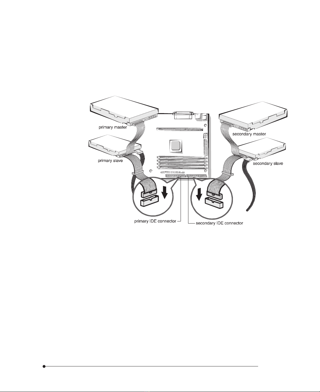
Enhanced IDE Connectors (CN22 and CN23)
You can connect up to four IDE devices (hard disk drives, CD-ROM drives, and
floptical drives) to the two IDE connectors (primary and secondary).
The PCI Bus Mastering IDE controller supports PIO Mode 3 and 4, and Ultra
DMA/33, a DMA data transfer protocol for IDE devices such as hard disk drives
or CD-ROM drives. The Ultra DMA/33 allows DMA commands to transfer data
at a maximum burst rate of 33 MB/sec. IDE devices must be capable of
supporting Ultra DMA/33 in order to enable this feature. Also, an Ultra DMA-
aware device driver (a Bus Master IDE driver) for your operating system is
required.
1-8 Introduction
The BIOS in the motherboard supports bootup from IDE CD-ROM drive,
floptical drive, SCSI drive or network drive. So, you can select a CD-ROM drive or
floptical drive as a boot device by setting CD-ROM or Floptical in the Advanced
Setup menu of the SETUP program.
After connecting the one end of the IDE ribbon cable to one of the IDE
connectors on the motherboard, connect the two connectors at the other end to
your hard disk drives.
Figure 1-4. Connecting the IDE Cable
If you install two hard disks, you must configure the second drive to slave mode by
setting its jumper accordingly. See the manual of your hard disk for the jumper
settings.
You may configure two hard disk drives to be both masters using one ribbon cable
on the primary IDE connector and another ribbon cable on the secondary IDE
connector. You may install one operating system on an IDE drive and another on
the other IDE drive and select the boot device through SETUP.
If you set up your CD-ROM drive as the primary master drive and boot the
system from the CD-ROM drive, the system will recognize the CD-ROM drive as
drive A and your drive A as drive B, and can not recognize your drive B.

1-9
Introduction
ATX Primary Power Connector (CN24)
You can connect an ATX-compliant power supply to the 20-pin block ATX power
connector. Connect the cable from the power supply to this connector. Make sure
that the cable from the power supply is aligned with the power connector on the
motherboard and then firmly push down the cable.
When using an ATX-compliant power supply that supports ATX specification 2.1,
connect the auxiliary power cable from the power supply to the 6-pin block auxiliary
power connector next to the ATX primary power connector.
Figure 1-5. Connecting the Primary Power Supply Cable
ATX power connector cable

1-10 Introduction
Front Panel I/O Connectors
The motherboard provides header connectors to support functions typically located
on the front panel of the computer and the illustration below shows the front panel
I/O connectors.
Figure 1-6. Front Panel Connectors
power LED
HDD LED
speaker
power switch
suspend switch
reset switch
keyboard lock

1-11
Introduction
Back Panel I/O Connectors
The illustration below shows back panel connectors that are located on the edge
side of the motherboard.
Figure 1-7. Back Panel I/O Connectors
Serial Port 1 and 2 Connectors (CN10, CN12)
You can connect serial devices such as a mouse, an external modem, or a serial
printer to either serial ports. By default, any device connected to the serial port 1
connector (the serial port 2 connector) is designated in software as COM1
(COM2). You can change these designations through the SETUP program.
Parallel Port Connector (CN11)
You can connect parallel devices such as a printer to the parallel port. By default,
any device connected to this port is designated in software as LPT1. You can set the
I/O address used by this port through the SETUP program.
USB Connectors (CN13)
You can connect peripherals such as scanners, printers and joysticks to the USB
(Universal Serial Bus) connectors. USB includes devices that in the past used serial
ports, parallel ports, the keyboard port, the mouse port, and game ports as well as
new kinds of devices. USB peripherals are hot-swappable enabling plug and play for
your peripherals.
PS/2 mouse
connector (CN14)
USB connectors
(CN13) parallel port (CN11)
PS/2 keyboard
connector (CN14) serial port 1 connector
(CN10)
serial port 2 connector
(CN12)

1-12 Introduction
PS/2 Keyboard Connector (CN14)
The PS/2 keyboard is connected to the connector.
PS/2 Mouse Connector (CN14)
The PS/2 mouse is connected to the connector.
Figure 1-8. Connecting Peripherals to the Back Panel Connectors
mouse
printer (parallel device)
modem (serial device)
CCD camera (USB device)
keyboard

2-1
Using the SETUP Program
Using the SETUP Program
Using the SETUP Program
Chapter 2
About the SETUP ProgramAbout the SETUP Program
About the SETUP ProgramAbout the SETUP Program
About the SETUP Program
You can use the SETUP program to change the computer's configuration
information when you installed or removed motherboard options.
The SETUP program is stored in your motherboard's read-only memory (ROM),
so you can run the program any time you turn on or reset the computer. You don't
need to insert a diskette or access a hard disk.
The configuration you define through SETUP is stored in a special area of memory
called CMOS RAM. The battery on the motherboard backs up this memory, so the
memory is not erased when you turn off or reset the computer. Whenever you
reboot the computer, it checks the settings, and if it discovers a difference between
the information in the CMOS RAM and its actual hardware configuration, it
prompts you to run SETUP.

2-2 Using the SETUP Program
StarStar
StarStar
Starting the SETUP Pting the SETUP P
ting the SETUP Pting the SETUP P
ting the SETUP Programrogram
rogramrogram
rogram
To start SETUP, turn on the computer. After the computer completes its self-test,
as soon as you see the message, press the Del key:
Hit DEL if you want to run SETUP
If you do not press Del quickly, the computer starts loading the operating system
and you will not be able to run SETUP. If happens, reset the computer again.
When you enter the SETUP program, you see the System Setup window.
SETUP is composed of four windows that contain several icons. An information
line at the bottom of the menu displays simple explanations for each option.
Figure 2-1. System Setup Window
Table of contents
Other TRIGEM Motherboard manuals


