TRIGEM LN620 User manual

Motherboard
User’s Guide
LN620

Disclaimer and Copyright Notice
All rights reserved. No part of this publication may be reproduced, stored in a
retrieval system, or transmitted, in any form or by any means, electronic,
mechanical, photocopying, recording, or otherwise, without the prior written
permission of TriGem Computer, Inc. No patent liability is assumed with respect
to the use of information contained herein. While every precaution has been taken
in the preparation of this publication, TriGem Computer, Inc. assumes no
responsibility for errors or omissions. There is no liability assumed for damages
resulting from the use of the information contained herein. Further, this publication
and features described herein are subject to change without notice.
Trademarks
TirGem is a registered trademark of TriGem Computer, Incorporated. Other product
names herein are for identification purposes only and may be trademarks of their
respective owners. TriGem disclaims any and all rights to those marks.
• Intel and Pentium II are registered trademarks of Intel Corporation, MMX is
a trademark of Intel Corporation.
• PS/2 and VGA are trademarks of International Business Machines Corporation.
• Microsoft, MS-DOS, Microsoft Windows 95, Microsoft Windows NT are
registered trademarks of Microsoft Corporation.
Copyright© 1997 by TriGem Computer, Inc.

Safety Information
Safety Information
Battery Warning Instruction
Caution
If battery is incorrectly replaced there poses a danger of explosion. Replace battery
only with the same or equivalent type recommended by the manufacturer. Discard
used batteries according to the manufacturer’s instructions.
Attention
Il y a danger d’explosion s’il y a remplacement incorrect de la batterie. Remplacer
uniquement avec une batterie du meme type ou d’un type recommande par le
constructeur. Mettre au rebut les batteries usagees conformement aux instructions
du fabricant.
Vorsicht
Explosionsgefahr bei unsachgemaäß em Austausch der Batterie. Ersatz nur durch
denselben oder einen vom Hersteller empfohlenen ähnlichen Typ. Entsorgung
gebraushter Batterien nach Angaben des Herstellers.
Fuse Warning Instruction
Caution
For continued protection against risk of fire, replace only with same type and rating
of fuse. Disconnect input power before servicing. Only connect this equipment to
an earthed socket outlet.
Vorsicht
Vor jeder service-arbeit netzstecker ziehen! Apparatet ma kun tilkobles jordet
stikkontakt.
Attention
Debrancher avant d’ouvrir.Apparaten skall anslutas till jordat nätuttag.
Atencion
Desconecte fuerza electrica antes del servicio. Laite on liitettävä
suojäkosketinistoraasian.

CONTENTS
Chapter 1 Motherboard Description
Features........................................................................................................ 1-1
Motherboard Overview .............................................................................. 1-3
Motherboard Connectors............................................................................ 1-4
Power Supply Connector ..................................................................... 1-5
Front Panel Connectors ........................................................................ 1-5
Rear Panel Connectors ......................................................................... 1-6
Board Expansion Connectors.............................................................. 1-9
FDD Connector..................................................................................... 1-9
Primary and Secondary E-IDE Connectors........................................ 1-9
Chapter 2 Using the BIOS Setup Program
About the Setup Program........................................................................... 2-1
Entering the Setup Program ....................................................................... 2-2
Exiting the Setup Program ......................................................................... 2-4
Setup Menu.................................................................................................. 2-5
Standard Setup Menu ........................................................................... 2-5
Advanced Setup Menu......................................................................... 2-8
Chipset Setup Menu............................................................................ 2-11
Power Control Setup Menu................................................................ 2-12
PCI/PnP Setup Menu .......................................................................... 2-14
Peripheral Setup Menu ....................................................................... 2-15
Utility Menu............................................................................................... 2-17
Detect IDE........................................................................................... 2-17
Color Set .............................................................................................. 2-18
Security Menu ........................................................................................... 2-18
Supervisor / User ................................................................................ 2-18
Anti-Virus ............................................................................................ 2-22

Defaults Menu........................................................................................... 2-23
Original................................................................................................ 2-23
Optimal ................................................................................................ 2-23
Chapter 3 Installing and Removing Board Options
Before You Begin ........................................................................................ 3-1
Installing the Pentium II Processor............................................................ 3-2
Installing the Retention Mechanism.................................................... 3-2
Installing the Pentium II Processor...................................................... 3-3
Setting the Processor Speed................................................................. 3-5
Upgrading to a Boxed Pentium II Processor............................................ 3-5
Removing the Pentium II Processor.................................................... 3-5
Removing the Heatsink Support Base ................................................ 3-7
Upgrading the Processor...................................................................... 3-9
Installing and Removing Memory Modules........................................... 3-10
Installing a Memory Module ............................................................. 3-11
Removing a Memory Module ........................................................... 3-11
Changing DIP Switch Settings................................................................. 3-12
The Things to do in Post-installation ...................................................... 3-13
Appendix A Specifications
Form Factor ................................................................................................ A-1
Processor..................................................................................................... A-1
Main Memory............................................................................................. A-1
Intel 440LX AGPset and PCI/IDE Interface ............................................ A-2
I/O features ................................................................................................. A-2
Five usable expansion slots ...................................................................... A-2
Other features ............................................................................................. A-3
Manufacturing Options.............................................................................. A-3
Power Supply ............................................................................................. A-4

Appendix B Error and Information Messages
BIOS Error Messages..................................................................................B-1
BIOS Beep Codes .......................................................................................B-3
Appendix C Motherboard Resources
DMA Channels............................................................................................C-1
Interrupts......................................................................................................C-2
Appendix D Update on Installing Windows 95
Installing the Bus Master IDE Driver....................................................... D-2
Installing the USB Driver.......................................................................... D-3
Installing the USB Driver.................................................................... D-3

1-11-1
1-11-1
1-1
Motherboard Description
Chapter 1
This chapter describes the major features of your motherboard.
Features
The motherboard supports the following features:
Slot 1 connector, 233 MHz, 266 MHz, or 300 MHz Intel Pentium II
processor with MMX technology
Three 168 pin DIMM sockets, support up to 384 MB of synchronous DRAM
(SDRAM) memory and support unbuffered EDO DRAM
512 KB of synchronous Pipeline Burst SRAM external cache on the substrate
in the Single Edge Contact (S.E.C.) cartridge
Two built-in PCI bus Enhanced IDE hard disk drive controllers, each channel
supports up to two hard disk drives or CD-ROM drives
Intel 82443LX PCI/A.G.P. controller
Intel 82371AB PCI/ISA/IDE Xcelerator
ITE 8679F super I/O controller
Two Universal Serial Bus (USB) interfaces
Three 32-bit PCI slots, one 16-bit ISA slot, and one shared PCI/ISA slot
One A.G.P. (Accelerated Graphics Port) connector
Motherboard Description
Motherboard Description

1-21-2
1-21-2
1-2
Motherboard Description
System and video BIOS shadow RAM
Plug-and-Play (PnP) BIOS feature
A built-in PS/2 style keyboard connector and a built-in PS/2 compatible
mouse connector
Two serial ports (one built-in connector and one optional pin header) and one
built-in parallel port
The following are manufacturing options:
Wake up LAN connector
Wake up Ring connector
Management extension hardware
Chassis security connector
System fan controller connector
TheAccelerated Graphics Port(A.G.P.) isahigh-performance
interconnect for graphic-intensive applications, such as 3D
applications.A.G.P.is independent ofthe PCI busand is intended
for exclusive use with graphical-display devices.
The motherboard has two USB ports; one USB peripheral can be
connected to each port. For more than two USB devices, an external
hub can be connected to either port. The motherboard fully supports
the universal host controller interface (UHCI) and uses
UHCI-compatiblesoftwaredrivers.

1-31-3
1-31-3
1-3
Motherboard Description
Motherboard Overview
Figure 1. Motherboard overview
Back panel I/O connectors
ISA connectors
ROM BIOS
Wake up LAN connector
PCI connectors
ITE 8679F super I/O controller
Intel 82443LX (PAC)
Battery
Serial port (COM2)
connector
Slot 1 connector
DIMM sockets
Chassis security connector
Speaker
Intel 82371AB (PIIX4)
A.G.P. connector
Front panel connector
System fan connector
DIP switch
Fan connector
(active heatsink fan)
Power supply
connector
Secondary E-IDE connector
Primary E-IDE connector
FDD connector
Wake up Ring
connector
IrDA connector
Management
extension hardware
Fan connector

1-41-4
1-41-4
1-4
Motherboard Description
Motherboard Connectors
Figure 2. Motherboard connectors
DIMM sockets
Power supply
connector
ISA connectors
PCI connectors
Serial port (COM2)
connector
Chassis security
connector
A.G.P. connector
Front panel connector
System fan connector
Fan connector
(active heatsink fan)
Secondary E-IDE connector
Primary E-IDE connector
FDD
connector
Wake up ring
connector
DIP switch
IrDA connector
Slot 1 connector
Wake up LAN
connector
Fan connector
1-51-5
1-51-5
1-5
Motherboard Description
Power supply
cable
Power supply
connector
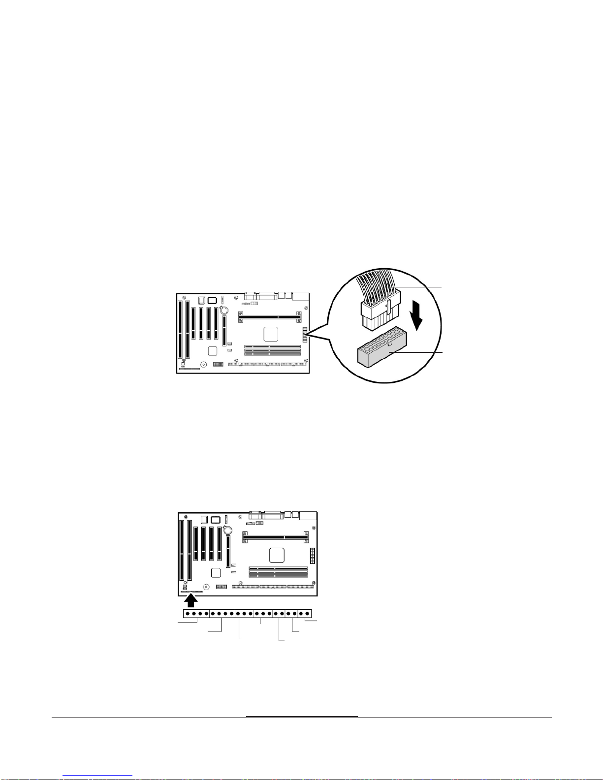
Power Supply Connector
The power supply converts AC power from a wall outlet to the DC voltages
required by motherboard and devices in your system. The power supply has a
large motherboard connector and several internal device (hard disk, CD-ROM,
and floppy disk drive, etc.) connectors.
The power supply should match the physical configuration of the chassis. Before
attaching all components, make sure the proper voltage has been selected. Power
supplies often can run on a wide range of voltages and must be set (usually via a
switch) to the proper range.
You can connect the power supply cable to the power connector on the
motherboard.
Figure 3. Connecting the power supply
Front Panel Connectors
The motherboard has connectors for controls and indicators typically located on
the front panel of the computer.
Figure 4. Front panel connectors
Speaker
HDD LED
Reset
Sleep button
Power button
Power LED
Key lock
1-61-6
1-61-6
1-6
Motherboard Description
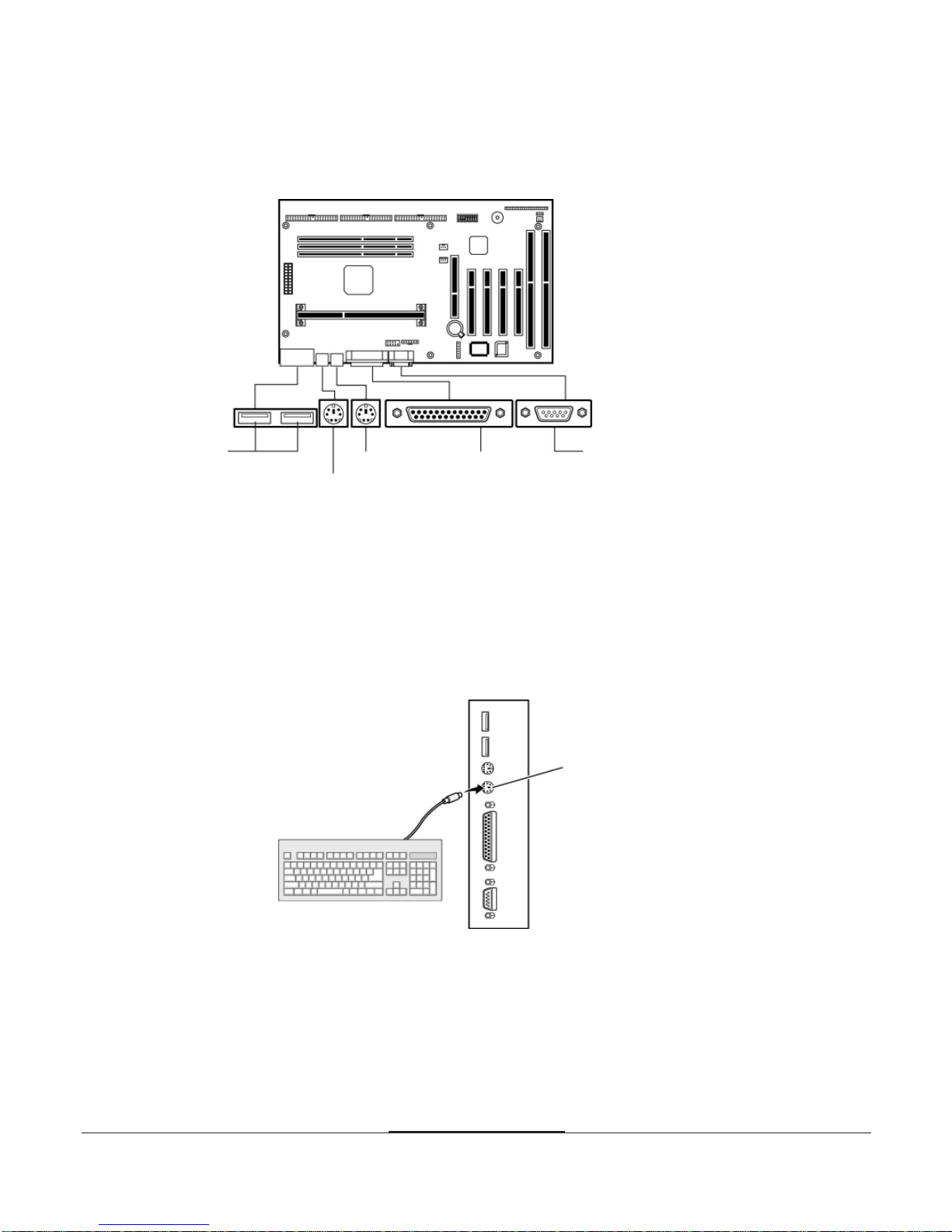
Rear Panel Connectors
Figure 5. Rear panel connectors
Keyboard Connector
Your system's PS/2 style keyboard plugs into the keyboard connector.
Figure 6. Connecting the keyboard
Keyboard
connector
Mouse
Serial port
Parallel port
Keyboard
USB ports
1-71-7
1-71-7
1-7
Motherboard Description
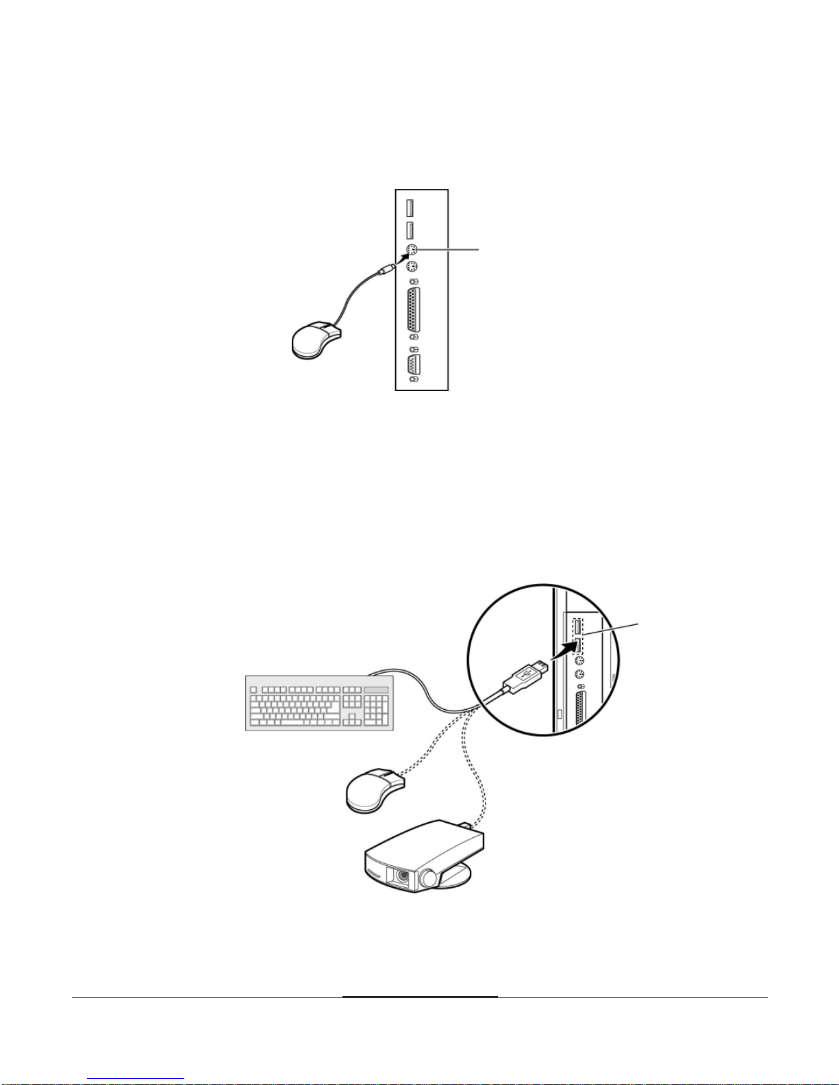
Mouse Connector
Your system's PS/2 compatible mouse plugs into the mouse connector.
Figure 7. Connecting the mouse
USB Connectors
You can connect any USB compliant devices to either of the USB connectors.
USB devices include low-speed peripherals such as microphone, digital joystick,
and speaker.
Figure 8. Connecting USB devices
Mouse
connector
USB ports

1-81-8
1-81-8
1-8
Motherboard Description
Serial Ports (COM1)
You can connect a serial device, such as an external modem and printer, to
the serial ports.
Figure 9. Connecting the serial device
Parallel Port (LPT1)
You can connect a parallel device, such as a printer, to the parallel port.
Figure 10. Connecting the parallel device
Serial port
Clips
Parallel port

1-91-9
1-91-9
1-9
Motherboard Description
Board Expansion Connectors
There are three PCI slots, one ISA slot, and one shared slot (for a PCI or
ISA card). The PCI bus supports up to four bus masters through the four
PCI connectors.
Also the motherboard has one Accelerated Graphics Port (A.G.P.) connector.
TheAccelerated Graphics Port is a high-performance interconnect for
graphic-intended for exclusive use with graphical-display devices.
FDD Connector
You can connect your diskette drive(s) to the diskette drive connector on the
motherboard by using the diskette drive ribbon cable. The diskette drive ribbon
cable has two connectors for diskette drives in general.After connecting the one
end of the diskette drive ribbon cable to the motherboard, attach the connector(s)
on the other end to the diskette drive(s).
Primary and Secondary E-IDE Connectors
Your motherboard has two built-in PCI E-IDE interfaces (primary and
secondary). Each interface supports up to two IDE drives (master and slave).
After connecting the one end of the IDE ribbon cable to the primary or
secondary E-IDE connector on the motherboard, connect the connector(s) at the
other end to your IDE drive(s) such as the hard disk drive or CD-ROM drive.
If you install two hard disks by using one IDE ribbon cable, you must configure
the second drive to slave mode by setting its jumper accordingly. See the manual
of your hard disk for the jumper settings.
You may configure two hard disk drives to be both masters by connecting one
ribbon cable (one hard disk drive will be attached to it) to the primary E-IDE
connector and another ribbon cable (the other hard disk drive will be attached to
it) to the secondary IDE connector. When you install one operating system on an
IDE drive and another on the other IDE drive, you can select the boot device
through the Setup program.

1-101-10
1-101-10
1-10
Motherboard Description
The hard disk drive controller on the motherboard supports Ultra DMA/33,
a DMA data transfer protocol for hard disk drives. This allows DMA
commands to transfer data at a maximum burst rate of 33MB/sec. Both
the controller and the hard disk must be capable of supporting Ultra DMA/33
in order to enable this feature.
The BIOS in the motherboard supports boot up from IDE CD-ROM drive,
floptical drive, SCSI drive or network drive. So, you can select a CD-ROM drive
or floptical drive as a boot device by setting the 1st/2nd/3rd Boot Device option to
CD-ROM or Floptical in the Advanced Setup menu of the Setup program.

2-12-1
2-12-1
2-1
Using the BIOS Setup Program
Chapter 2
About the Setup Program
This chapter explains how to use the BIOS Setup program.You can use the
Setup program to change the computer's configuration information and boot-up
sequence, etc.
The Setup program is stored in the computer's read only memory (ROM), so you
can run the program at any time when you turn on or reset your computer.You
need not insert a diskette or access the hard disk.
The Setup program lets you verify or change the followings:
On the Setup menu, you can set up and modify some of the basic options of
a system, such as time, date, diskette drives and hard disk drives.
On the Utilities menu, you can perform system functions.
On the Security menu, you can specify password that can be used to limit
access to the system.
On the Default menu, you can select a group of settings for all BIOS Setup
options.
Using the BIOS Setup Program
Using the BIOS Setup Program

2-22-2
2-22-2
2-2
Using the BIOS Setup Program
The configuration you define through the Setup program is stored in a special
area of memory called CMOS RAM. The battery on the main board backs up
this memory, so the memory is not erased when you turn off or reset the
computer. Whenever you reboot the computer, it checks the settings, and if it
discovers a difference between the information in the CMOS RAM and its actual
hardware configuration, it prompts you to run the Setup program. If this
happens, just press F1 to run the Setup program and then correct the setting.
Entering the Setup Program
To enter the Setup program, turn the computer on and press <Del> when you
see the message:
"Hit DEL if you want to run SETUP."
As soon as you see this message, hit the DEL key. If you do not press DEL key
quickly, the computer starts loading the operating system and you will not be
able to run the Setup program. If this happens, reset the computer again.
When you enter the Setup program, you will see the Setup menu.
For reference purposes, you should write down the current Setup settings.
When you make changes to the settings, update this record.
2-32-3
2-32-3
2-3
Using the BIOS Setup Program
The Setup program is composed of four windows that contain several icons.
An information line at the bottom of the menu displays simple explanations
for each option.
You can use your keyboard or mouse to select the options.
The mouse functions are click (change or select both global and current field) or
double click (perform an operation in the selected field).
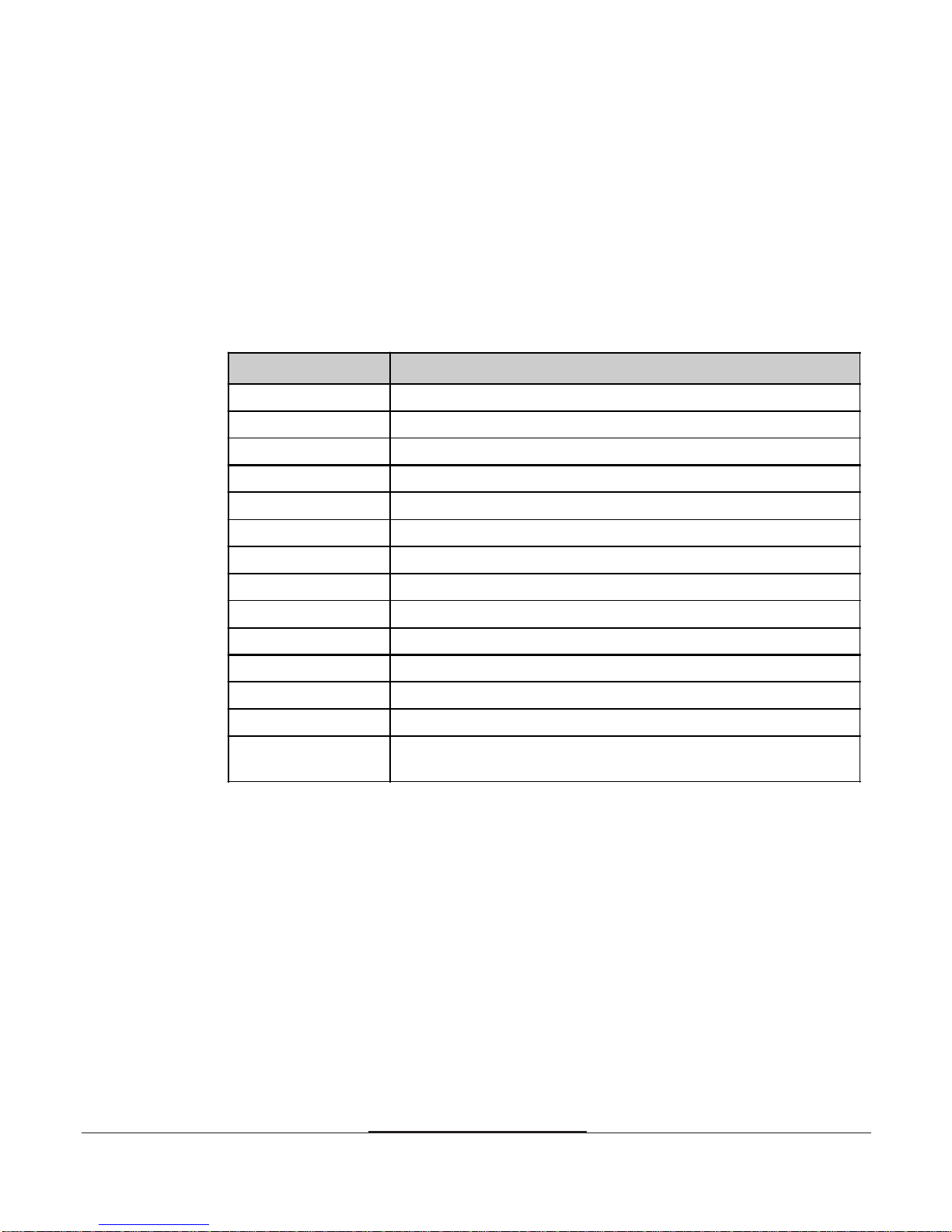
The following list provides an overview of function keys in the Setup program.
Setup Key Description
Tab Moves to the next window or field.
Moves to the next field to the right, left, above, or below.
Enter Selects the current field.
+ Increases a value.
- Decreases a value.
Esc Closes the current operation and return to previous level.
PgUp Returns to the previous page.
PgDn Advances to the next page.
Home Returns to the beginning of the text.
End Advances to the end of the text.
Alt-H Accesses a help window. It describes the keys available in Setup
Alt-Spacebar Exits System Setup
Alphabetic keys A to Z are used in your keyboard
Numeric keys 0 to 9 are used in either the numeric keys along the top of the
keyboard or the numeric keypad.
↓
↓
↓
, , ,
or
↓
2-42-4
2-42-4
2-4
Using the BIOS Setup Program
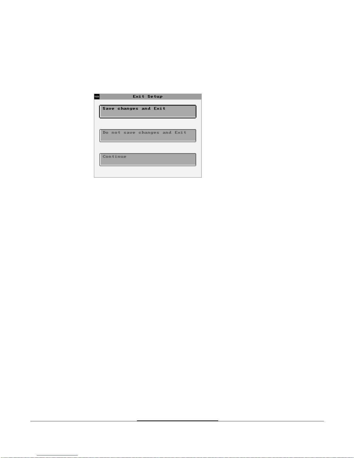
Exiting the Setup Program
To exit the Setup program, pressAlt and Spacebar keys simultaneously.
If you press these keys, you can see the following window.
To save the settings and exit, select Save changes and Exit. The system reboots
with your new settings.
If you want to exit the Setup program without saving your settings, select Do not
save changes and Exit. The system reboots with your original settings.
To return to the Setup menu to make corrections, select Continue.
If you saved your changes or quitted without saving the settings, the Setup
program resets the system and the computer performs its power on diagnostic
tests.
If your computer detects a problem in your Setup configuration, you may see an
error message and a prompt to run the Setup program when it is rebooting.
Follow the instructions on the screen to run the Setup program and correct the
problem.
Table of contents
Other TRIGEM Motherboard manuals


Popular Motherboard manuals by other brands

VIA Technologies
VIA Technologies EPIA-M840 operating guide

VIA Technologies
VIA Technologies KT400A user manual

Acorp
Acorp 4845GLQ manual

Texas Instruments
Texas Instruments DS320PR412-421EVM user guide

onsemi
onsemi FUSB15201DUAL60WGEVB Test Procedure

ON Semiconductor
ON Semiconductor ALPINE NCRHA926 user manual


