AMS TSL2540 EVM User manual

User guide
TSL2540 EVM
TSL2540 ALS, Light-to-Digital Sensor Evaluation Kit
Version 1.0

TSL2540 EVM User Guide
Page 2
Contents
1Introduction........................................................................................................................... 3
1.1 Kit Contents..........................................................................................................................3
2Getting Started.....................................................................................................................3
3Hardware Description........................................................................................................... 3
4Software Description............................................................................................................4
4.1 Connect Software to Hardware............................................................................................4
4.2 System Menus .....................................................................................................................5
4.3 System Level Controls .........................................................................................................6
4.4 Auto Polling..........................................................................................................................7
4.5 Device ID Information...........................................................................................................7
4.6 Log Status and Control Information .....................................................................................7
4.7 “ALS” Tab .............................................................................................................................8
5Resources..........................................................................................................................10

TSL2540 EVM User Guide
Page 3
1 Introduction
The TSL2540 evaluation kit comes with everything needed to evaluate the TSL2540 ALS, Light-to-
Digital sensor. The device features advanced digital Ambient Light Sensing (ALS) with two output
channels for visible and IR light.
1.1 Kit Contents
No.
Item
Description
1
TSL2540 Daughter Card
PCB with TSL2540 sensor installed
2
EVM Controller Board V2.2
Used to communicate USB to I2C
3
USB Cable (A to Mini-B)
Connects EVM controller to PC
4
Flash Drive
Include application installer and documents
Figure 1. Evaluation Kit Contents
2 Getting Started
The software should be installed prior to connecting any hardware to the computer. Follow the
instructions found in the Quick Start Guide (QSG). This loads the required driver for the USB
interface and also the device’s graphical user interface (GUI).
The balance of this document identifies and describes the controls available on the GUI. In
combination with the TSL2540 datasheet, the QSG and application notes available on the ams
website, www.ams.com, there should be enough information to allow evaluation of the TSL2540
device.
3 Hardware Description
The hardware consists of the EVM Controller, the TSL2540 EVM daughter card, and a USB
interface cable. The EVM controller board provides power and I2C communication to the daughter
card through a seven pin connector. When the EVM controller is connected to the PC through USB,
a green LED on the board flashes once on power up to indicate the system is getting power.
For schematics, layout and BOM information, please see the documents included with the install
located in the TSL2540 EVM folder (All Programs -> ams -> TSL2540 EVM -> Documents).

TSL2540 EVM User Guide
Page 4
Figure 2. Evaluation Kit Hardware
4 Software Description
The main window (Figure 3) contains the system menus, system level controls, device information
and logging status. The ALS tab contains controls for the light sensing function. The application
polls the ALS data continuously and calculates the lux.
Figure 3. Software Main Window
4.1 Connect Software to Hardware
On startup, the software automatically connects to the hardware. On successful initialization, the
software displays a main window, containing controls pertinent to the connected device. If the
software detects an error, an error window appears. If “Device not found or is unsupported”
appears, verify the correct daughterboard is properly connected to the EVM controller board. If
“Cannot connect to EVM board” appears, verify the USB cable is connected. When the EVM

TSL2540 EVM User Guide
Page 5
controller board is connected to the USB, a green LED on the board flashes once on power up to
indicate the USB cable is connected and providing power to the system.
If the EVM board is disconnected from the USB bus while the program is running it displays an error
message and then terminates. Reconnect the EVM board and restart the program.
4.2 System Menus
At the top of the window there are pull-down menus labeled “File”, “Log”, and “Help”. The File menu
provides basic application-level control. The Log menu is used to control the logging function, and
the Help menu provides version and copyright information for the application.
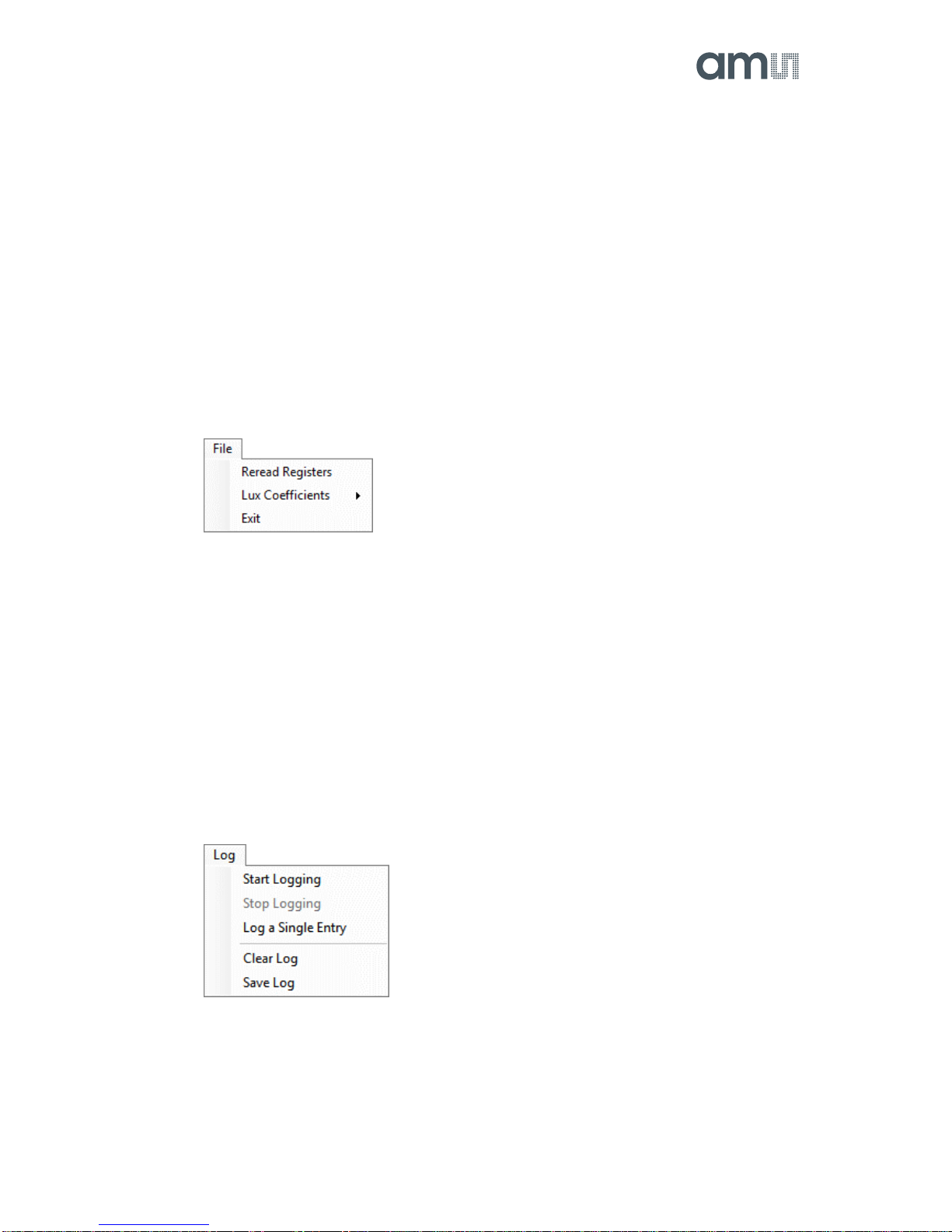
4.2.1 File Menu
The File menu contains the following functions:
Figure 4. File Menu
The Reread Registers function forces the program to re-read all of the control registers from the
device and display them on the screen. This does not read the output data, because those
registers are continually read while the program is running.
The Lux Coefficients menu allows the user to Display, Load or Save the lux coefficients used to
calculate lux. See ALS Lux Coefficients section for more details.
Click on the Exit command to close the main window and terminate the application. Any unsaved
log data is cleared from memory. The application can also be close by clicking the red “X” in the
upper right hand corner.
4.2.2 Log Menu
The Log menu is used to control the logging function and to save the log data to a file. Log data is
accumulated in memory until it is discarded or written to a data file.
Figure 5. Log Menu
Click Start Logging to start the logging function. Each time the program polls the output information
from the device, it creates a new log entry showing the raw data values, the values of various
control registers, and the values entered by the user into the text fields near the bottom right corner
of the window.
Click Stop Logging to stop the logging function. Once logging is stopped, the data can be written to
a file, or the user can continue collecting additional data by clicking Start Logging again.

TSL2540 EVM User Guide
Page 6
The Log a Single Entry command causes logging to start, collect one single entry, and
immediately stop again. This function is not available when logging is already running.
Click Clear Log to discard any data that has already been collected. If there is data in memory,
which has not been saved to disk, this function displays a prompt asking to verify it is OK to discard
the data. If the log is running when this function is clicked, the log continues running after the
existing data is discarded.
Click Save Log to save the collected log data to a csv file. This stops the logging function, if it is
active, and displays a file dialog box to specify where to store the logged data. The default file
name is described in the Log Status and Control Information section, but the file name may be
changed if desired.
4.2.3 Help Menu
The Help menu contains a single function: About.
Figure 6. Help Menu
The About function displays a dialog box (Figure 7) showing the version and copyright information
for the application and library. Click the OK button to close this window and continue.
Figure 7. About Widow
4.3 System Level Controls
Immediately below the top menu bar there are checkboxes used to control the system level
functions of the TSL2540 device.
The Power-On checkbox controls the PON function of the TSL2540. When this box is checked, the
power is on and the device can operate. When this box is unchecked, the power is off and the
device does not operate (The control registers can still be written, but the device does not function).
The ALS Enable checkbox controls the AEN function of the TSL2540. When this box is checked,
the device collects and report ALS data as programmed. When this box is unchecked, the ALS
functions do not operate.

TSL2540 EVM User Guide
Page 7
4.4 Auto Polling
The application automatically polls the TSL2540 raw ALS data if enabled. The Poll Interval displays
the time between reads of the device.
4.5 Device ID Information
The lower left corner of the window displays the ID number of the EVM Controller board, identifies
the device being used and displays the ID of the device.
4.6 Log Status and Control Information
The lower right corner of the window contains status information and controls for the logging
function:
Figure 8. Logging Status
This section contains text boxes that are stored in the log file data and used to build the file name
for the log file. If the data in these fields are changed, the new values are stored with any new data
logged. The default log file name is based on these values at the time the log file is written. If
nothing is entered in these boxes they default to a period (“.”).
Sample default file name:
TSL2540_1-2-3_Log_HH_MM_SS.csv
From Application
From User Input
The Count value displayed is a count of the number of samples currently in the log buffer.
The Elapsed Time value indicates the elapsed time since data logging was started.
The final field in this section controls the number of log samples to collect and then automatically
stop and save the log data. Once the count of the log entries reaches the amount shown in this
field, the program stops logging and pops up a window asking for a file name to save the collected
data. After saving the collected data the log is cleared and the count is set back to zero.

TSL2540 EVM User Guide
Page 8
4.7 “ALS” Tab
The main portion of the screen contains a tab labeled ALS. The controls in this tab are divided into 3
sections, each performing a separate function.
Figure 9. ALS Tab
4.7.1 ALS Controls
The left side of the ALS tab contains controls to set various ALS settings.
The ATIME control sets the time of the ALS integration. ATIME can be adjusted in 2.778ms steps.
The AGAIN control is a pulldown menu which sets the analog gain of the ALS sensor. The values
available are 1/2x, 1x, 4x, 16x, 64x, and 128x.
The WEN checkbox controls the ALS Wait feature. When this box is checked, the values for
WTIME and WLONG are used to determine the time between ALS cycles. When this box is
unchecked, there is no wait period between ALS cycles and the values of WTIME and WLONG are
ignored.
The WTIME control sets the time to wait between ALS cycles. WTIME can be adjusted in 2.778ms
steps.
The WLONG checkbox controls sets the WTIME factor. When this box is checked, the wait time
between ALS cycles is extended by a factor of 12x.
4.7.2 ALS Lux Coefficients
The TSL2540 ALS supplies information that is used to calculate Lux (unit of illumination). The Lux
equation for the TSL2540 uses a combination of data from the sensor and various coefficients to
calculate the Lux value. The software is pre-configured with coefficients for an open-air
configuration. When the sensor is placed behind glass, different coefficients should be loaded into
the software to update the Lux equation. The coefficients can be loaded or saved to an XML file
using the File menu. To ensure the proper XML format first save the current coefficients using File >
Lux Coefficients > Save. Once the file is saved located the XML file created and edit with a text

TSL2540 EVM User Guide
Page 9
editor such as notepad to change the coefficients. Then go to File > Lux Coefficients > Load and
select the XML file that was updated.
The software can also automatically load new coefficients upon starting the GUI. To do this save the
XML file as TSL2540_luxeq.xml in the system documents directory
(%USERPROFILE%\Documents, also known as My Documents). Then restart the GUI and see a
dialog appear with the new coefficients displayed.
If you are experiencing trouble loading new coefficients, this may indicate a problem with the file
format. The XML file must contain all the required Lux equation elements to be loaded. The format
of the file follows the standard XML format and is as follows:
<?xml version="1.0" encoding="utf-8"?>
<!-- Device:TSL2540 Saved:9/22/2017 4:22:11 PM -->
<luxeq>
<eq_values>
<coef name="DGF" value="58.514" />
<coef name="CoefB" value="0.202" />
<coef name="CoefC" value="0.893" />
<coef name="CoefD" value="0.147" />
</eq_values>
</luxeq>
4.7.3 ALS Output Data
The top right corner of the ALS tab displays the output data. This data is continuously read. The
polling interval is shown above the tab.
Visible displays the data counts for the Visible channel
IR displays the data counts for the IR channel
Lux displays the calculated lux based upon the channel counts and lux coefficients
4.7.4 ALS Data Plot
The remaining portion of the ALS tab is used to display a running plot of the collected ALS values
and calculated Lux. The last 350 values are collected and plotted on the graph. As additional values
are added, the old values will be deleted from the left side of the graph. To start the plotting
function, check the Enable Plot checkbox and select the Visible, IR, or Lux checkbox.

TSL2540 EVM User Guide
Page 10
Figure 10. ALS Data Plot
The scale of the Y-axis of the plot can be adjusted by clicking on the small up and down arrows at
the top left corner of the plot. The scale can be set to any power of 2 from 64 through 65536.
Click the Clear Plot button to discard the current data and continue plotting the new data. Note if
the Clear Plot button is clicked while the plot is disabled, the data is discarded, but the actual plot
will not be updated until the plot function is re-enabled.
5 Resources
For additional information regarding the TSL2540, please refer to the datasheet. For information
regarding the installation of the TSL2540 EVM host application software please refer to the
TSL2540 EVM Quick Start Guide.
Designer’s Notebooks dealing with various aspects of optical measurement and optical
measurement applications are available. All content is available on the ams website www.ams.com.
Addition Resources:
TSL2540 Datasheet
TSL2540 EVM Quick Start Guide (QSG)
TSL2540 EVM User’s Guide (this document)
TSL2540 EVM Schematic_Layout

Mouser Electronics
Authorized Distributor
Click to View Pricing, Inventory, Delivery & Lifecycle Information:
ams:
TSL2540-EVM
Other manuals for TSL2540 EVM
1
Table of contents
Other AMS Motherboard manuals