Yaesu FT-990 User manual

FT-990
OPERATING
MANUAL
YAESU
MUSEN
CO
.,
LTD
.
c.P.O
eox
1soo
TOKYO,
JAPAN

General Information
The Ff-990 is a high performance transceiver
providing
up
to
100
watts transmitter power out-
put
onall HFamateur radiobandsinON,
SSB,
FM,
RTTY
and
Packet
(F1
and
F2)
modes, and
up
to
25
watts carrier in
AM
mode. The receiver tunes all
frequencies between100kHzand
30
MHz
in
10-Hz
steps.
An
automaticantenna tunerandiambicelec-
tronic speed keyer
/bug
simulator are built in as
standard accessories, along with five
IF
filters for
the 2nd and 3rd receiver IFs, and a universally
tunable, digital switched capacitance filter
(SCF)
for receiver audio. The
Fr
-990
maybeordered with
or
without
an
efficient,
heavy-duty
switching
regulator
AC
powersupply.
Inside the Ff-990, modular construction with
plug-in composite epoxy boards provides excel-
lent
RF
circuit isolation, high reliability
and
serv-
iceability. Two 10-bit direct digital synthesizers
(DDS)
and a magnetic rotary encoder provide si-
lent, silky-smooth tuning, pure local signals and
very fast
t/r
changeover important in QSK CW
and digital modes. Frequency accuracy and stabil-
ity are assured
by
driving all DDSs from a single
master oscillator,
and
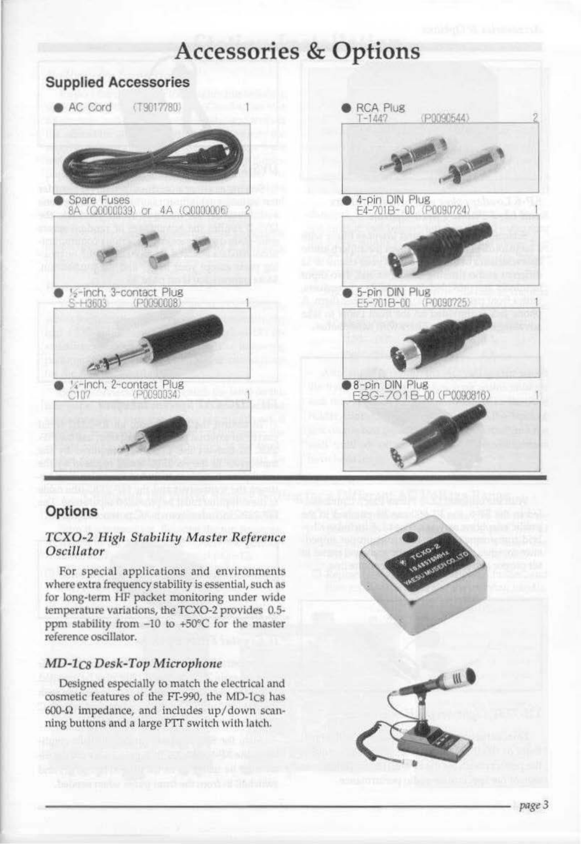
the optional TCX0-2 tem-
perature-compensated oscillator is available for
exceptional 0.5-ppm stability from -10
to
+50
°C.
The extremely low-noise, high-performance re-
ceiver front end uses PIN-diode-controlled push-
pull FEfs in a constant-gain
RF
amplifier, feeding
an
active double balanced
quad
FET
ring mixer.
Six microprocessors in the Ff-990 are program-
med
to
provide the simplest possible control inter-
face for the operator, even for previously complex
applications like HF packet. Interference rejection
is facilitated
by
both
IF
shift and
an
IF
notch filter,
with pushbutton selection of IF bandwidths, and
the astounding dual digital
SCF
audio filter with
independentlyadjustable selectivityskirts (unique
to the
Ff
-990).
An
automatically mode-dependent
AGC selection is provided along with manual
AGC decay selection/disable.
The front panel keypad provides 1-touch band
selection, with two independent (A/B) vfos for
each band holding their
own
frequencies, modes
and
IF
bandwidth settings, and even clarifier off-
sets and repeater shifts, if used. Switching bands
instantly recalls all of these settings last used on
each band. Ninety freely tunable
and
scannable
memories are selectable with single
(MEM)
knob,
each storing all of the operating data held in a vfo.
Otherimportantfeatures includegeneral coverage
reception from 100kHz
to
30
MHz, a jack
an,d
front
panel button for a separate receive-only antenna,
an effective noise blanker, all-mode squelch, inde-
pendentreceive
and
transmit clarifiers, 6-function
multimeter
and
a unique adjustable passband-
shifting
RF
speech processor which lets you tailor
transmitter audio to your
own
voice for
SSB.
Special features for CW include a built-in iam-
bic memory keyer, presettable bfo offset and spot-
tingbuttonfor precise tuningbyzero-beat,
and
key
jacks
on
both front and rear panels.
In
addition
to
the facilityoftheSCF audiofilterfor CW reception,
a 250-Hz 3rd IF filter is available as an option to
complement the 2nd IF 500-Hz bandwidth
IF
filter
(also optional in the DC version).
Special digital mode provisions include sepa-
rate interface jacks for
an
RTTY
terminal unit and
packet tnc, and
RTTY
and
PKT
mode selection but-
tons which disable the microphone jack automat-
ically while providingeither sideband for
RTTY
or
LSB/FM modes for packet: switch between voice
and digital modes with only the
push
ofa button.
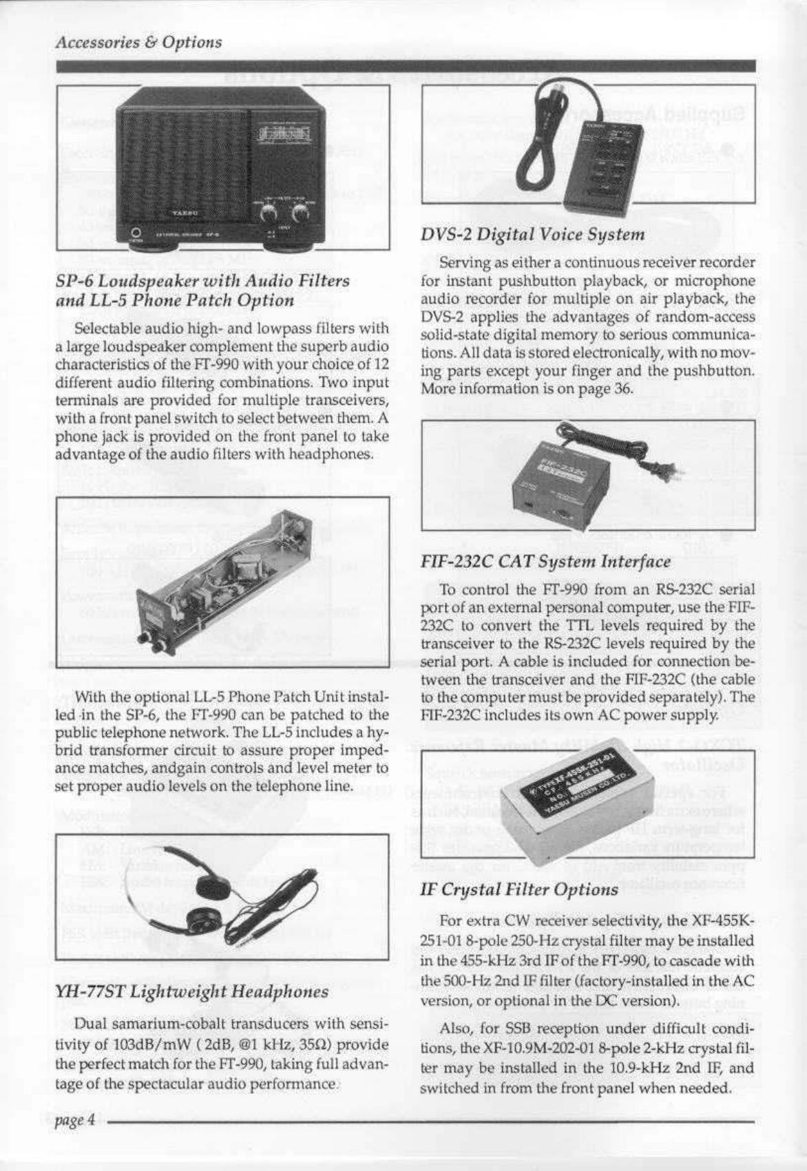
For voice contesting, the
DVS-2
digital voice re-
corder option introduced with the Ff-1000 works
with the Ff-990, providing continuous-loop recei-
ver recording
and
pushbutton
transmission
of
multiple voice messages
to
help keep you
at
your
peak QSO-rate throughout the contest.
With its efficient internal AC switching supply,
the Ff-990 weighs only
13
kg andalways runscool.
Aninternalheatsinkand quiet, thermallyswitched
blower allow full power
output
withoutrear panel
protrusions, giving easy access
to
connectors. The
Fr-990 incorporates the same high-speed antenna
tuner as the
Ff
-1000, with its
own
microprocessor
and
39
memories which automatically store most
recentantenna matching settings for nearly instant
recall while changing operating frequency.
Accessories include the SP-6 Loudspeaker with
audio filters and optional
LL-5
Phone Patch; the
YH-77ST
Headset; the
FP-25
AC
PSU (for DC ver-
sions) or DC Cable (for AC versions) and the MD-
1c8
Desktop- and MH-1
88
Hand Microphones.
Before connecting power, please read the
Instal-
lation
section carefully, heeding the warnings in
thatsection
to
avoid damage to theset. After instal-
lation, please take time to work through the
Opera-
tion
chapter, referring
to
the
Controls
&
Connectors
chapter as necessaryfor details. These chapters are
intended to be read while sitting in front of the
Fr-990, so you can try out each control and func-
tion as they are described.
page
1

Specifications
General
Receiving frequency
ran11e:
100
kH
z-
30
MHz
Transmitting frequency
r~nges:
160-m band,
1.8
to
2.0
MHz
(or 1.81/1.83
to
1.85)
SO·m
band,
3.5
to
4.0
MHz
40-m band, 7.0 to
7.5
MHz
30-mband,
10
.0 to
10.5
MHz
20-m
band,
14.0
to
14.5
MHz
17-mband,
18.0
to18.5MHz
15-m
band,
21.0
to
2J
.5
Mllz
12·m band, 2.
4.5
to
25.0
MHz
10
·mband,
28.0
to
29.7
MHz
Frequencystabilit
y:<
10
ppm
from
-10
to
+50
•C
(except
FM,
<
200
IIz),
<
0.5
ppm
from
-
10
to
+50
OC
w/TCX0·2 option
(FM
<150Hz)
EmiSsion
modes: ISB/USB()3E), CW
(AlA),
FSJ<
()1
D,
J2D),
AM
(A3E),
FM
(F3E)
Baskfrequencysteps:
10
Hz
for
JSE,
AlAand Jl
D;
100
IIz
fo
r
A3E
, F3Eand
)20
Ante1u1a
Impedance: 16.5lo t
SOn
(SOn
nominal)
Supply vol
tage:
100-117
or200-234
VAC±10%,50/60 Hz
Powerconsumption(approx.}:
60
VA
receive, 470
VA
for
100
wattstransmit
Dimensions (WHD):
368
x
129
x
370
mm
Weight (approx.): 13 k
g.
(28.6
lbs)
Traus
mitter
Power
output
adjustable up
to
100 watts (25watts
AM
carrier)
Duty
cyde:
100%@100watts,
50%@100
watts
(FM
& RTfY,3-minute tx)
Modulation types
SSB
:
Bala
nced, filtered carrier
AM:
Low-level (early s
tn
ge)
FM:
variablereactance
FSK
: Audio frequency shift keying
Maximum
FM
deviation: ±2.5 klIz
FSI<
shiftfrequencies:
170,
•1
25
and 850Hz
Packet
shUt
frequencies:
200,
1000
Hz
Harmonicradiation:
at
least
50
dB
below peak out·
put
SSB
carriersu
pp
ressi
on:
atleas
t4
0
dB
below peak
ou
tput
Und('Slred sideband suppresion:
at least
50
dB
below peak output
page2
Audio response
(SSB):
no
t morethan
-6
dB
from
400
to
2600Hz
3rd·ordet
!MD.
-36
dB
typical@
100
watts
PEP
on
14.2
MHz
Microphone impedance: 500 to600n
R
ece
iver
Circuittype:
triple-conversionsuperheterodyne
Intermediatefrequencies:
47.21
and
10
.9
4
Mllz
1
nnd
455k
Hz
Sensitivity;
(lo
r
lO
dBS/N
,Od
ll~
·
lfiV)
Frtquency
=> 100-250
250-soo
I os-1s
18-30
Mode
I
BWl
ll
kHz
kHz
IMz !Nit
sse.cw
<4)N <I)N
<2)N
<025
JN
(2.
4
khz)
AM
<10~V
<2!1V <4!1V
<
111V
{6kHZ)
29
MHlFM
---<
P-5
J.11
(for
12
d~
SI
NA
\))
Selectivity
(-6/-SJ
dB):
Min
imum
Maximum
Bun
on
Modes
-6
CIB
BW
-60
CIB
BW
2.4
kHl
att
except
FM
22kHz
2.0
kl-lz
an
exc.
AM
, FM
I.B
kHz
500
Hz
cw.
A.
m.
Packe
t
500Hz
250Hz
cw.Rm
24
0Hz
-
A~l(wklo)
6kHz
Squelchsensitivity:
1.8-
30
MHz
(CW,
SST3,
AM):
<
2.0
~V
28
-
30
MH
z (FM): <
0.32
~v
LF
rejection (l.S-
30
MH
zl:
80
dB
or better
lmngl' rejection
(1.8
-30
MHz):
80
dB
or bel!er
lFshift range: ±
1.2
kHz
Maximum
audiopoweroutput:
2 wattsInto4n with <
10%
THO
Audio output impedance: 4
to
80
40~z
3.6~Hz
1.8
IlHz
700
IIi
IS
kH
z
Speciftca
tiar
(s
rue
~Jibj~~CIIo
cllangc
,
iu/Jr~
in
t
eres
t
of
technical
i
mpr
iJ!ICmenl,
wi
tho11lnot
ice
or
obli·
galion.

Accessories & Options
Supplied
Ac
cessor
ies
•
Sp
ar
e
H:i'Ses
eA
((JQ[
G0039
I c 4A
(QOO:JQ006J
e •,-inch. 3-contact
Pl
ug
H •
M~J9C""OO"""-!!
·
--
--i
e '.-
In
ch
.
2-co
nta
ct Pl
ug
(,
llJ'/
_.:'
I...::Jf:C~9~0""J:'-";4
__
___
1
Options
TCX0-2
High StnbilitiJ Master Refereuce
Oscillator
For special applications and
environments
whereextra frequency stability isessential,such as
for long-term HF packet monitoring
under
wide
temperature variations, theTCX0-2 provides 0.
5-
ppm
stability from
-10
to
""50"C
for the master
referenceosdllator.
MD
-
lcs
Desk-TopMicrophone
Designed especially
to
match the electrical and
oosmelic features of the
FT-990,
the Ml
).lcs
has
600.!2
impedance, and includes
up/down
scan-
ning buttons and a large P1T switch wilh latch.
e
RCA
Plu
g
1-1?4?
~St.<)
e
4-P
in
DIN
P
lug
E4-
7C
l
l:3-
00
1PC0907Z
4
\
page3

Accessories &
Optio11s
SP-6 Loudspeakerw i
th
Audio
Filters
andLL-5 Phone Patch Option
Selectable audiohigh- and
low
pass
filters with
a large
lOudspe'*er
oomplementthe superb
audio
characteristics of the IT-990 wi
th
yourchoiceof12
different
a.udio
filtering combinations. Two
inpu
t
terminals are provided
for
multiple transceivers,
witha
front
panel
sw
itch
to
selectbetween them. A
phone
jack is provided
on
the front
panel
to
ta)<e
advantage
of
the
audio
filte
rs wit·b headphones.
With theoptional
LlrS
Phone
Patch
Unitinstal-
led·in
the
SP
-6, the FT-990 can
be.
patched
to the
public telephonenetwork.
The
LL-5
includesa hy-
brid
ttansformer circuit
to
assure proper
imped-
ance matches, andga
in
controls
and
level meter
to
setproper
au.dio
levels
on
the
'telephoneline.
YH-77ST
Lightweight
Headpl1011es
Dual samarium-cobalt transducers with sensi-
tivity
of 103dB/mW (2dB,
@1
kliz,
35!1) provide.
theperfectmatChfor the
FT-990,
taking full
advan-
tage of the spectacularaudio performance.
page4
DVS-2
Digital
Voi(:e
System
Serving
as
eithera continuous receiverrecorder
ior instant pushbutto·n playback,
or
1nicropbone
audio
recori:.fer
for
multiple on air playback, the
DVS-2
appli.es
the advantages of random-access
solid-state digital memory
fo
serious oornmunica-
tions.
All
data
is
Sto
redelectronical
ly,
with
nomov-
ing parts except your finger and tne pushbutton.
More
infonnation is
on
page
36
.
FIF-232C
CAT
System
Interface
To control the
FI'
-990 from an
RS-232C
serial
pc:Jrt
of
an external
pet$()nal
computer,
use
thE
rFIF·
232C
to
con
vert
the
TT"
levels r¢quiied
.Qy
the
transceiver
to
the
RS-232C
levels required by the
serial port. Acable is included
fo
r connection be·
tween the
transceiv:er
and
the
Fli"-232C
(the cable
\0
t,heeqtnpu
ter
must
be
provided separately),
The
Fl~·232C
includes itsown ACpowersupply.
IF
Crystal
FilterOptio11s
For extra
CW
receiver selectivity, the
XF-455I<-
251
-
01
8-pole250-Hzcrystalfilter.may
be
installed
in
the455-kHz3rd
1Fof
ihe
FT
-990,
to
cascade with
U1e
500-Hz2nd lF filter ((actory,lnstall
ed
in theAC
ver.sion,
or
optional in the
DC
version).
Als<J,
for
$SB
reception
under
difficult condi-
iions, theXF-10.9M-202-
0,
&-pole
2-kHzcrystal
fil.
~r
may
be
inst(llled
in
the
10
.
9-kHz
2nd
IF,
and
switched
in
from
the
frontpanel
when
needed.

Station Installation
Prelimi11ary
Iuspection
Inspect I
he
transceiver thoroug
hJ
y
immediate!
y
upan
opening
the
packing
ta
rton.Check
to
see
that
all controls
and
switches
work
freely,
and
inspect
the
cabinet
for
any
signs
of
damage.
Make
sure
Lhe
;1ccessory
fus~.s
and
plug
s pictnrud
on
page
-3
are
included. If
any
damage
isfound
document
it
com-
pletely, -
and
co
ntact t
he
shipping
company
(or
dealer,
if
you
putchascd
it
over
the
coun
ter) right
away.
Save
the
pa
c
king
materials in case you need
to
return
the
se
t for service,
lf
you
pu.rchased optional internal accessories
separately, install them as described
in
lnslaJiing
Jntt'l'nnl
AccesMrii!S
(page
45
).
Power
Connection
The
Fr~990
is available
in
an
AC/D
C version,
whi
chJn
dud<'S t
he
EP-25
switch
ing
power
supply,
and
a DC-only version. Page
4.7
describes
DC
in-
stallation
tor
both
versionS,
wh
i
le
the
fo
ll
owing
p~ragrapl~
describes
on
ly
ACpower
conn\i(:tions
for the AC/OCversion.
Before connecting power,
check
the label
on
the
rear
panel
which
indicates the AC
m~inl)
voltage
range
for
which
your
transceiver
is
curren
tly set.
If
your
ACmains
voltage is
outside
of
thi;s
tange;
the
voltage
switch
ott
the
pawer
supply in
the
trans-
ceiver
must
be
reset,
and
three
fuses
must
be
CAU'T'IO)Il!
Pet
lllammt d«
II1Clg
'C
will
t'
i?
Sl
llt
if
im-
pr
oper supply v
olta
ge
is
appli-ell
to
·
th
e
-
tnms
ce
ive
r. Yotrr
wa
r.
rmrf1J
iio
ts
11
Qt;
cov
er tlama
gC>
ca
used
by
appli
ca.t
ion
of
iwprop._
er
srq1ply
v
o1
t
(l
ge, or IISil
(I
f
im
-
prop
i!
r fuses.
changed.
This
requir
es
only
a
screwdriver
and
is
not
difficult(seebelo
w)
,
out
you
should
make
sure
the
power
supply
is
set
correcHybeforeconnecting
power.
If
you
have
any
doubts
about
the
proce-
dure,
ask
your
dea
l
er
for help.
You
should
~lso
make
sure
the fuse in
the
rear
panel fuse
holder
is (;orrect for
your
mains
voltage:
AC Mai
ns
Voltage
Fus
e Capa
city
100 - 117
SA
200-234
4A
Af
t
er
making
certain the
AC
voltage for
which
the
t:rnnsceiver is
set
matches
your
llUlins voltage,
and
that
the
correct fuse
is
installed in the
fuse
holder,
co
n
nec
t the
AC
power
cotd
to the:
3-pln
AC
jack
on
t
he
rear
panel. Don'tpl
u!.{
the
cord into the
wa
ll until all
other
transceiver interconnections
have
been
made
.
Cl1angin
.g
th
e Power S
uppl
y Se
ttin
g for a
Di
ff
er
e
nt
AC
Volta
ge
R
an
ge
0
Make
c~rtain
that
all
cables
a~e
disconnected
from
the
transceiver. Remove
the
lop
cover
qS
shown
at
l:he
top
of
page
10,
<)nd
tnc
bo
t
tom
cov
.
er
as
shown
at
the
bottom
of
pag
e
12.
0 Move the
switch
next
to
the
speaker
(see
be-
low) to
the
required
115
or
230 V
side
.
I
•
J
nov--
~~v
0
On
the bottom
of
the
chassis
(see
below)1 re-
place
fuses PH6901
and
FH6902
with
two
of
the
supplied
fuses:
either
the 10-A fus.es (for
'100-
1'17
VAG)
or
5-A
(for200-
234 VAC).
0 Repl
ace
the
f·
use
in
the rear panel holder,
and
then
rep
lace
t]1e
cover
an
d
the
c.~
rtyinghi!nd.le.
lmpo:ttant!
lf
yo
u
·
~hl!
nge
t
il
t'
AC
Vo
/f
,1!1t
r
tmge
S#,
l
tlug_
y
O!i
mliSt
cJ
w11
ge>
1/t
e"fwo
ill
-
le
ma!
f
u
s~.a
nd
th~
fw
;e
in
th
e r
fflf
tn
nel
ll
olsler.
Jl/§q
l!j:
~
'ltr
e
to
cfitmg~
tlte.
vo/tlrgr
ma
rking 0
11
t
ll
ulhll~lli
t
l
tlu
tr~
ll
f
pt
uwl
to
m
atc
h
th~
11
ew
w
ll
age
setlil!$,
Do
/
11'-~
J
islrs!or
~,_
ut
Mu,
JR<eS-
page$

Station-Installation
Trattsceiver Location
To
assurelong.life
of
thec:omponents,a primary
consideration insetting
up
the Fr-990 is providing
for adequate ventilation arolll1d the cabinet.
The
cooling system
of
theFr-990
must
be
free
to
draw
cool airin at thebottomrear
of
the transceiver,
and
to
expel
warm
air
out
of
the
upper
rear panel. Do
not place the transceiver
on
top
of
another heat·
generating
devi~e
suth
as a linear
amp
l
ifi-er,
and
do
not
placeequipment, books
or
papers
on top
of
the ttansceiver. Place the transceiver
on
a
h~rd,
flat
surface. Also1 provide a few centimeters
of
space
on
either s
id
e
of
the transceiver, ifpossible.Avoid
heating vents
and
wi11dow
locaUons that could
expose the transceiver toexcessivedirectsunlight,
especially inhcit climates.
Grounding
For protection from shock
and
properperform·
anee, connect the
GNO
terminal
on
therear panel to
a
good
earth ground, using a heavy
braiM
.d cable
of
the
shortest length possible. All other station
equip
ment
should
be
. co
nnected
to the
same
grounding cable, as close together as practical.
1f
you
use
a co
mputer
with
or
near the t-r-
990,
you
may need to experiment
with
grounding
of
both
the lranscei"ver
and
thecomputerto
suppress
com-
puter
noise
in
thereceiver.
Adjustittgthe FrontFeet
The
two front feet
of
the flr:990 can
be
set in
eiU
1
erof
twopositions.
By
turning the-knurledring
around a
(
retr
~c
ted
)
.footclockwise, the middle
of
thefootwill extend
about
one
centimettY.
'TUrn
the
ring as far
115
it
will
gd
(abOut1
1.1
-turn) to lock the
extended foot in place.
To
retract
an
extende.d foot,
tum
the knurled ring
courtterclockw~e
~-tum
while pressing
on
thecenter
of
the.foot.
Adjusting
the
Front Feet
Anten11a Considerations
Any antennas.connected to
the
Ff-99.0 should
have coaxial feedlines
with
50-0 impedance, rurd
includewell,grounded lightning arrestors.
for
the
antenna
at
the-main
ANT
ja
·ck, the antenna tun
er
in
the fT-990 is capable
of
matchingaJltennas with
an
SWR
of
up
ro
3:
1
or
more
on
the amateur
bands
to
the transmill'er. Nevertheless,
optimum
perform-
.ance for both reception
and
transmission will
gen
-
erally result
with
an
antenna designed to
provide
a
50
-
12
unbal;1nced resistive load
at
U1e
operating
frequency. An anteM.a
that
is
not
rE!Sonant
at
the
oper.aling frequency maypresent too high
an
SWR
for
proper
matching with the built-in a
ntenn
a
tuner, in
wh
i
ch
ca~e
·
the
antem1a
itself shou
ld
be
readjusted,
or
an
outboard
antenna
tuner used.
If
the tuner
is
unable to bring the
SWR
down
to
an
acc;eptable leVel, attempting to tra·
nsmitwill
result
in
a.n
automatic reduction
in
power ou"tput
and
increased losses in the feedJine. Opera.tion lll1der
such conditions
is
notrecommended:
it
is better to
install another
an
t
enna
designed for· that band.
Also,
ifyour
;lritenna hasa balanced feedpoint
and
vou
ltse a balanced feedline; install a balun
be-
tween
the
feedline
and
the.transce
iver's
.
ANT
jack.
The same precautions.
apply
to
any
additional
(receive-only) antenna connected
to
U.1e.
RX
AN
T
IN
jack, except
that
this
ru1t
·enna
will
not
have
the
bei)_e
fi
t
of
the built-in antenna
tu~.
Therefore,
lm\ess.such areceive-onJy ·antenna has
an
imped-
·ance near
50
n at the operating frequency, you
may
need
\11\
.extt>mal tu.ner forgood performance.
Interco.nttecfion
of
Acces~>ories
The diag.rams on the·following
pages
show
in·
tercrimiediqllS
of
external accessor!es.
li
you
have
any questions
on
tbe$e accessories
or
connecting
devices nol
shown,
contact
your
dealer for advice:
MemoryBackup
The
lithium memory
BAC
KUP
swi
tch inside the
t
op
access
panel
Js
turiled
on
at
thefactory, allow-
ing
vfo
and
memory
data
to
be
retained while
power is off. Backup current
Js
miniscule,_so it is
n
ot
necessary to
tum
the
BACKUP
switch off unless
U1e
transcei
ver
is
to
be
st
ored
for·a long.time.
Af
ter
about
five years
the
transceivermayfail to
retain
memo
ries(althoughoperationwill
be
other-
wiSe
un
affect
e<l),
and
thelithiumbattery
should
be
replaced. Ask
your
deal.
er
for replacement
of
the
battery,
or
for instructions
on
how
to
do
so
your-
self.
page6
---------------------------

Station Installation
Co1111ector
Pinouts
DOT
KEY
G"'D
EXTSP
--------------------------
------~-
RC
~
A
~P~
L=UG~
------------------------
------~
SIGNAL SIGNAL
or
(+j
GND
G"'O
or{-)
prlge
7

Station Installation
Connecting
External
Accessories
Connecting External Accessories
0 0
EXT
SPKR
SUPPLIED
CABLE
(T9101275A)
AC
SUPPLIED
CABLE
A
(T9100980)
pageB
------------------------------

Station lustallation Connecting Extetnal
Accessories
DATA
10
.
0k!il
13.SV
Linear
Amp
T/R
Switchjng
Options
on
the
REMO
TE
Jack
=
FT-990
non-OSK
Linear
Amp.
0
~-
-,.--.-,.o;l
._1
L
J-
0
~
~
$
00
~
EXT
AL.C
1
ANT
Cmmecting aLinear Antplifier
If
usfng
an
ft.-7000 wiU'
Lh
e Fr
.9.9
0,
use
optional
cable
Di\00019 topro\(idec,1utomatic
band
selection
for
th,~Jlin$,
~s
.
W~,?Il
~
QSK
L/r
switching
Ql:.Introl
.
For
aJl)!
ether
lil)l)ar ampliTier, t/ r
switc\;Un~
is
provided
by
thE!
REMoTE
j~ck
(page
~3}.
t'o
clelermine
whicn
pills
ro
use
t f(rst
petermine
Ute
ur.en
circuit
vOltage and:
do~ed
circuitcurrent requirements or
lhe
t/
r
switching
line
fOr
thdinear.
If
the
voltagEriS
.
AC
oi
abov.e50.
V:OC
,
or
if
theocurrent
required
is
more
thl)n
50P
mA,
switch
S6~01
rnt~sl
be
set
[o the
RY
posl;lion to el\abJil.theintl)mal teli!y
(S9801
1:9
·
set
to
the
TR
position
to
.disable
the
relay
at
the
factory,
see
page
1·1).
Otherwise,
if
the
linear's
ryl(juirement~
arii!
Bet~wth~~e
j
connEfc::lthe
(>l:lsftiye
~~
r
«it\trollirtc
tiom
th~
lirrear to
pin~
of
the
REMOTE
jaek<,lmd
the
nep1Live
side
of
thi.S
line
to
pin3
(~und)
.
Also,
if
ytllrr linear-'s
requirements
are
tvi
thin
th
e1\have
rang-e, and if
it
iS
d~ignec!
for
ru
n
\)rea'k-in
(QS:'K5
<:>peration,
you
~·ill
need
to connect lts
exciter•enableo\1
~ul
to
pin
8 of I
he
~D
DATA
jat.k.
With
a plug installed
in
_thl;~
jaCk,
the
l;rartsmitteris
normally
diSilbled,
and
ph\' 8
float!>
at
about 5
vo
l!s.
By
grounding
pit\
8-
(to
)'in
3),
the
QSK
linear
enab
l
es
t
he
trtmsmitt
llt
(U.
tis circuHpre ents u,e
Ff-990
fTom
~xc(ting
th
e
linear
b~>'fore
kjs
I'eady
to
send).
Noh~
that
the
Fr-99'0
will
not
transmit
!fa
plug
is
installed
in
the
BAND
DA
TAjack
and
pin
8 is1lol
,graundeij,
WiU,
lhe
relay
enabled
?tfie Fr-9!i0
can
suppOrt
non-
QSKllneilr
t/r
vo
lta
ge
up
t;p
.125
VAC
@200
mA
1
e,
r
DC
v(lltage
up
tt>
220
V@
300
n\A,
.
or
ct~~-tircu.Jh:;hrr(lnt
up
to
2 A With
QC
volta:ge~p
to
~m:v.
Use
pin
5
of
the
·
REMOTE
jack
(:reiay
comJROn).,.
and
pin
4
(closed-on
-transm
i~l,
after
se
tling·
S6801
to
the
IW
p,Oilllion
.
C9Q
flol aUitfflpi QSK
Oftell!t
jpn
tuith
al
htetJr
if
its
~wit.c11iltg,requires
tile
relay
£!!iilP/IiJI.
page.9

Station Installation Internal
Adj14strnents
Intemal
Adjust1nents
Described below
are
a
fi?w
intemaIsettingsyou
may
wish to
make
as
you
become familiar
with
the
FI-990. Access
to,
and
adjustment of, all
user
-ad-
justable settings
are
described together here since
it
is mostconvenient
tO
do
all that
you
need
at
once
while the covers
are
removed. However, descrip-
tions
of
the
purpose
and effect
of
these adjust·
ments are provided elsewhere ir\ this
manual,
where.appropriate.
We
therefore recommend thai
you
do
not
make
any
o.f
theseadjustments until the
purpose
and
effect
of
eachis
dear
to
you
.
All adjustments have been al
igned
or
set
at
the
factory to standard settings,
but
in
some
cases you
will
want
to tailor them for
your
particularstation
requirements. Be careful, however, to avoid tam-
pering with other intermil
co11trols
n!Jt mentioned
in
this section,
so
you
don't
degrade
alignmen
t.
Forfull alignmentdetails covering all internal
set
·
lings,ri!fer to the
Fr-990Techrrical
Ma11ua/.
CAUTION!
Some
ef
these
t;~djuslmer~ts
must
be
made
zvilh
power
applied
,
and
with
the
cover
re"
tfiQ.Ved.
A.lfli'attglt
the
'I,!Oltagtts
a,t
e;\!{OSI!~
places
.
in
the
trrmsceiver
are
not
danger-ous
to
you
.,
siilSitive-
cir-c
uitn;
attn
be
daiffnged
by
t;!)
lltacf
wilh
rnetq1lic
tools.
Th
erefore~ve
rt!commend
using
.
(I
rronrmetalli
c
ndjus.t·
77llmt
tap/,
if
available.
In
an!!
case,
troaid
touchin
s,.,
any
components
not
ir1valved
in
tire
adjustment,
arttl-do
nq.f
allow..
anything
to
fil
l/
In
the
set
while
tire
cover
is
removed.
Button
Beeper
Volttme
This trimme!' p>otentiomet
er
sers the volume
of
the beep
that
s.ounds
when
one
of
the front panel
buttons
is
pressed
(independently
from
receiver
signal volume
as
set
by
the
AF
control).
0 Remove the ten screws
shown
at
the
upper
right,nnd remove the
top
cover.
0
Turn
the transcehrer
0ll
1
and
adjust
the
AF
con·
trol for normal volume
on
backgrotmd noise
on
a
~
comm<in.ly-used
band.
0 Referring to the photos
<~t
the right, locate
VR3011
and
use
a small screwdriver to
adjust
lt
for
the desired beep
volume
while repeately
pressil1g a butt(in.
-
..
••
Top
Cover Removal
Adjustment
Points·
Top
of
Chassis
..
~~10----------------------------------------------------
•

CWSitietone Vohtme
0 flollow
the
sam
e
steps
and
r
ef
er
to
the
same
photos
as
abovelor Button
Beeper
Volume,
but
adjust
VR3009
· while pressing (only)
the
SPOT
button
·
on
the front
pan
e
l.
·
CW
Keyer Weighting,
Bug
Sim~tlation
0 With
the
top
cov
.
er
~:emoved
as
·described for
Button Beeper Volume, notice
th
e small rectan-
gular
hole
near
thefronte
dge
.
of
thechassis,
ju
st
behind
the
left
side
of
the
panel
meter.
The
CW
keyer setting
switches
are accessible through
l.his
hole(weightingDlPswitch
1;>lockS7Z041s
a
little to
the
left,
and
tambic/bug
sl.ide
switch
57203 to
the
ri&h
t). The
photo
at the
fight
shows
a view
of
these
switches
from
the rear.
0
To
change
the switch settings
you
will
need
a
thin,
sharp-pointed
tool
about
15
em
(6 ind1es)
long, and prefer
ably
non
-metallic,
to
reach the
switches through l.he
ho
le.
You
can
watcrh
what
you're
doing
through
the
slot
bet\voon the top
edge
of
the front
panel
nnd
Ute
chassis, to the
left
of
the meter.
0 Slide
switch
57203
to
the·
lef~
(when
view
ed
frotn
the
front) to
change
the
keyer
to
simulate
a
bug
(dits
on
qne
padd
le,
and
steady
CW
on
the other)1
or
leave
ltsel
to
U1e
right
to
provide
iambic keying (factorydefault).
0
To
set
t
he
keyer
weighting (dot:dash ratio),
set
the foursectionsofi;llP
sw
i
tc11S7204
according
to
the table
below
(0
=ON=
front position).
Linea.r A.mp TIR
Switch
(56801)
0
The
location
of
lliis switch is
indicated
in
th
e
photos
on
the·
previous
pag
e.
Move
it
fo·rward
to
enable
the
TI Rrelay
at
pins 2,4
and
5
of
the
REMO
TEjack.
TI1e
factory default(back) position
Keyer
Weigl1t
Settings
Oot:oash
DIP
Swi
tch
Oot:
Oa
sh DIPSWit
ch
Ral
lo
1 2 3 4 Ra
ti
o I 2 3 4
1:3
.0 .0 0 0 0 1
;.4
.0 0 -0 -
1:3.1
-0 0 0 1:4.1 - - 0 -
1:
3.2
0 -0 0
f:A
.2 0 0 -0
1:3
.3 --0 0
1
:4-~
-0 --
1:3.4
0 0 -0 1:
4.4
0 ---
1:3,5
-0 -0 1:4.5 ----
1:3.6
0 --0
1:3.7
- - - 0
ON(IronlposlliOn
)• 0
1:3
.8 0 0 0 -
OF
F
(rear
pos
ll!o
n
)
~
-
1;
3.9
-0 0 -
Station Installation Internal
A.djuslme:nts
CW
Keyer
Switches
(As
viewed
fro
m
the
Rear)
has
pin 4
bf
this jock switched
by
transiStor
Q91QI,
and
the
ro.lay
d~abJed.
Sec
the jack'de-
scription
in
the
next
chaptllr.
R.
em· Panel
Audi
.o
Output
Levels
<.RTIY
•
VR3004,
PACKET
·
VR3CJ:06,
AFOUT
·
VR3010,
DVS-2 -vR3015)
Note:
these
controls cannot
be
adjusted
while
the
set
is on,
so
ad
j
ustment
may
have
to
be ma
de
by
trial-and-error. Make
sure
to
tum
the transceiver
off
each lime before
pulling
or
reinserting
fli
e cir-
cuit
board
.
0
Make
sure
the tnmsce!veris turned off.
0
R~1ove
rhe
top
cover, ifnecessary,
as
described
above
for
Beeper
Volum
e,
and
lift
out
the
bla<:k
plastic label
sheet
for
the
Top
Pan
elControls.
0
Remove
the
screw
at
each
end
of
the AF
Unit
(the board
ii\
the
middle
slo~),
and
gently pull
up
on
the brackets
at
each
end
of
the
board to
remove
it
(rock them alternately).
0 Refer
to
the AF
Unit
photo
at
the
Lop
of
the
next
page
for locations
ofthe
PKT
OUT,
RTIY
OUT,AF
OUT
and
o
vs
OUT
lrbnmers
on
the
board
,
Make
a
slight
adjustment
• clockwise to increase the
output
level,
or
countercloc)<wise tp
de~ase
it
.
0 Temporarily replace the AF-
Unit
in
its slot, till·
ing
care
to align the front
and
back edges
of
the
card
with
the
guide
.tabs
in
the chassis.
0
Tum
power
on
and
do
whatever
you
ne:ed
to
check
whether
the
output
level
is
satisfactory.
Jf
not, tum
lhe
pcrw
ifr
off
and
repMt
the
last
f!!w
steps until it it;.
0
Rep
lace lhe
two
screws
at'fixing the
AI'
Unit
,
and
replace the plastic label
sheet
so
that
the
controls
are
visible
through
the
holes
.
----------------------------------------------------------
-
~ge11

StationInstallation
Internal
Adjustments
AF
Unit-
Audio
Out
Trimmer
Locations
Mode-SpecificTufting
Rates
0 R-emove the topcover,
if
necessa:ry,
as described
abovefor ButtonBeeperVolume,
and
lift
out
the
black
plastic label
cover
for the
Top
Access
Panel
Controls.
0 Remove
U1e
screw
al
eac
h
end
of
fue ConlTol
Unit (the boar.d in
U1e
tightmostslot},
and
gen-
tly pull
up
on
U1e
brackets
at
e.'ch
end
of
lhe
board to r
emove
it
(rock themaltemately).
0 Refer
to
the
Control
Unit
photos
al
fhe
right
for
locations
of
the
split
pads
to
~alve
tuning
~;ates
for
each mode. Carefully
bndge
the
halves
of
the
pads
c:ort<>spon.<;ling
to
the
modc(s)
on
which you
wan
t
to
reduce
U1e
tuJ1ing,spel:!d.
0 Replace lhe
Contro
lU
ni
t
in
its
slot, usingcare to
allgn
the
front and back edges
of
the
car<!.
with
the
g~tide
tabs
in
the cl1assis.
0
Replace
the
two
screws
affixing
the
Contro
l
Uni
t,
andrep
1a
ce the plastic label
shee
t
so
that
the
controls are visible
through
the.holes in the
sheet.
Slow
AM
Auto
AGC
0 Remove the topcover,ifnecessary,
as
described
at the start
of
~his
section
for
B'utton Beeper
Volume,
Then
carefully turn
the
set
upside
-
down, and remove the t
en
screws
shown
at
th
e
right, affixing the bottom cover. Remove the
bottom
cover.
0 Referring to the
ph
o
t<:l
s on !he
next
page, loc;ate
the
split
pad
indicated,
and
ca
r
efully
short the
halves
of
U\e
pad
with
so
lder.
0 Replace
the
.
botlum
cover
and
its t
en
screws
.
and
U\en the
top
cover.and its ten screws.
Control
Unit-
Split Pad Locations
't'
Bottom CoverRemoval
page12----------------------------

AGCAuto.]umpedor
AM
(Bottom
of
Cha
ssis)
StaJionlllstp/lat'ioll
In
te
rn
al lld
jt.
IS
tment
s
---------------------------------------------------------pa
ge13

Controls & Connectors
Front Patrel Controls
I
ll
\
2·
~~t
\_
4
l·-
i
3
--
7
II
12
This
c
hapt
er
dt>scribes each control
and
connec-
tor
on
the
PT-990.
You
ca
n
ju
st
read
through
quickly
now,
but
some
of
the descriptions will be
more meaningful if you first work through the
Getting
Stt1rted
Tutorial
at
the
beginning
of
the Ofl·
era
lion chapter,
and
then return
to
this
chapter
with
the
set
powered
up,
as questions
arise
during
op-
eration.
Some
controls
and
switches are disabled
under
certain conditions.
(1)
POWER
This
bullon
turl'S
the
transceiver
on
and off.
(2) 2-Position Ptlsltbutton Switcltes
IU
AN
T
When
this switch is
in
the
undepressed {
a)
position, the antenna connected to
the
main
ANT
socket
is
used forreceive(it
is
always used
for transmit). When this switch
is
depressed
(
-)
,
the
IU
AN
T
IN
l
OUT
jacks
on
the
rear
panel
are
activated,
with
either a receive-only
antenna,
external receiver
or
in-line receiver
accessory. See the schematic
on
page
27
for
an
idea
of
how
this works.
HOX
This
button
may
be
used
in place
of
a micro-
phone
P'lT switch
or
CW
key
to
manually
activate the transmitter.
It
must
be
in
U1e
on-
depressed (
.-)
position forreception.
vox
Enables
automatic
voice-actuated tr<msmilter
switching in voice modes;
and
semi
break-in
keying
in
CW
mode.
The
con
trols aiJ'ecting
VOX operation
are
in
the
lop
access panel.
An
Press
this
button
when
receiving
on
a noisy
band
or
when
strong
signals
are
present.
This
inserts a 20-dB
attenuator
in
the
front
end
to
protect the receiver from overload.
(3)
PHONES
Th
is
Y,
-inch,3-contact jnckaccepts either
mon-
aura
l
or
ster
eo
headphones
with a2-
or
<l-eon-
tact
p
lu
g .
When
a
plug
is
inserted,
the
loudspeaker
is
disabled.
Audio
Is
supplied
to
both channels
of
a
stereo
headphone.
(4) M
ET
ER
Selector
This selector
detemllnes
the
function
of
the
mullimeter
during
transmission.
The
mean-
ings
of
the
abbreviations
are
as
follows:
PO
RF
Power
Output
(watts)
IC Final amplifier collector
current
(Amps)
SWR
S
tan
ding
Wave Rallo (forwa
rd
:reflected)
COMP
IU?
~peech
compressor level (in dB,
for
SSB
modes
only)
A
LC
relative Automatic Level Control voltage
vee Fi
nal
amplifiercollectorvoltage.
~ge14---------------------------------------------------------

The meter indicates the selected parameter
during transmission, and signal strength in
S-units during reception (on the top scale).
Each S-unitis approximately 6
dB.
(5)
AGC
Selector
Selects receiver AutomaticGainControl decay
time for most comfortable reception, or dis-
ables receiver AGC
(off).
Normally this switch
is set
to
the
AUTO
position, which automatically
selects the AGC decay according
to
youroper-
ating mode. When set
to
OFF,
the S-meter is
disabled, and strong signals may be distorted.
(6)
PROC
-@>-KEVER
Bothofthese controls function only when acti-
vated
by
the buttonwith the same name
at
the
bottom right side of the panel.
The inner
PROC
control sets the compression
(input) level ofthe transmitter
RF
speechproc-
essorinSSBmodes, and the outer
KEVER
control
sets the keyer
/bug
simulator keying speed.
(7)
KEY
Jack
This %-inch, 3-contact jack accepts a CW key
or keyer paddles (for the built-in electronic
keyer),
or
output
from an external electronic
keyer.
You
must
not
use
a
2-contact
plug
in
this
jack.
Pinoutis shownonpage
7.
Key
up
voltage
is 5
V,
and
key
down
current is
0.5
rnA. There
is anotherjack with thesame name, connected
in parallel with this jack,
on
the rear panel.
(8)
MIC
-@-
RF
PWR
The inner
MIC
control adjusts the microphone
input
level for
SSB
and
AM transmission.
Theouter
RF
PWR
controladjusts the transmitter
output
power in all modes. The adjustment
range is from less than
10
to
100
watts (or 5
to
25
watts in AM mode).
(9)
SQL
-@-
NB
The inner
SQL
control sets the signal threshold
at
whichreceiver audiois muted (and the
BUSY
LED
turns off), in all modes. This control is
normally kept fully CCW, except when scan-
ning,andduringFMoperation.Scanningstops
when the squelch is open.
The outer
NB
control adjusts the blanking level
when the noise blanker is activated during
reception.
If
set very far clockwise, receiver
audio can be distorted.
Controls & Connectors -Front Panel Controls
(10) AF-@-
RF
The inner
AF
gain control adjusts the volume
of the receiver in the speaker or headphones.
The outer
RF
gain control adjusts incoming
signal level infrontofthe receiver
RF
amplifier
(viaPINdiodes),intandemwiththegainofthe
receiver
IF
amplifiers. This control
is
normally
set fully clockwise for maximum sensitivity.
When rotated counterclockwise from maxi-
mum, the S-meter minimum deflection point
will move
up
thescale. Thepeak deflection for
a particular signal will remain the same if it is
greaterthanthe levelset
by
thiscontrol,
but
the
main receiver will be insensitive to weaker
signals.This controlalso affects the
SQL
setting,
and should be preset fully clockwise
when
setting the squelch threshold.
(11)
MIC
This 8-pin jack accepts the
MD-1Bs
or MD-1cs
Desktop Microphone or the
MH-1BS
Handie
Scanning Microphone. Pinout is
shown
on
page
7.
Propermicrophone
input
impedanceis
500
to
600
ohms.
(12) Left Side Push Switches
RF
FSP
Whenoperatingin
an
SSB
mode, you canpress
this button to toggle the
RF
speech processor
on
and off (for transmission). Processing level
is set by the
PROC
control,
and
the filter pass-
bandcan beadjusted. Whileactivated, the
LED
above this buttonglows orange. This button is
disabled in other modes.
KEVER
&
BK-IN
Whenoperatingin CW mode, the
KEVER
button
toggles the internalkeyer
on
and off, and
BK-IN
turns full break-in
(QSK)
CWoperationonand
off. The green LEDs above each button light
when
active. These buttons are disabled in
other modes.
NB
This button toggles the receiver noise blanker
on
and off. The LED above the button glows
green while activated. Blanking level is set by
the control with the same name.
(13) Mode
Buttons
These seven momentary buttons select the op-
erating mode, indicated
by
the
LED
in each
button. Note that pressing the
RTTY
and
PKT
---------------------------------------------------------------
page15

Cot1trols &
C01me~:tors-
Front Panel Co11trols
(packet) buttons multiple times willswitchbe-
tween thepossiblemodes
of
.emission thatcan
be
used
by
these digital
modes
(I.SB
and
USB
for
InTY,
and
LSB
and
FMforp.aaket).
(14)
FAST
Forfasttuning,pressthis
butto
n whilerotating
the luning knob
or
pressing
the
UP
or
DOWN
button,
\O
increase the tuning rate len times.
See
the table
on
page
2~
for
all
availablesteps.
While
the
fast tuning
rat
e is active,
FAST
is
displayed above t
he
MHz
digits.
You
can
set
the function
of
this
button
to
be
either"press-
and
-hol
d",
or
toggle
on/off;
I?Y
hbl
ding
the
button while switching the transceiver
on
.
(15)
Main
Ttuling
Knob
This knob
adjusts
the operating frequency
of
the vfo or a recalled memory.
Tu
ning incre-
ments ;u'e normally
10Hz
(100Hz
in
AM
and
FM
modes). The markings
on
the knob repre-
sent
50
increments
eadl;
and
one
full
tum
of
theknobprovides1,000increments(10kHz,or
1'00
kHz
in
AM/FM).
Ii
you preferslow
er
tun-
ing
rates
CY.I-speed}
you can install
an
lnteJnal
jumper
as
described
on
page
12.
Di
sp
lay B
righ
tne
ss
Adjustment
IM
brightness
of
the.dt;pl<~5'
(but
not
the
me·
terl'ilo~
or
LEDsl
isadjustable
by
hOlding·the
rm
bi.rtton:whi
fe
turrung rh
e.
CLAR
oontr
oL
(16}
LOC
K
TI\lsbutton toggles locking
of
themaintuning
knob to
prevent
accidentalfrequencychanges.
LOCK
is
disp
layed above
them
ode
buttons
when
locked (the·knOb canstillb¢
turned,
but
it
do~
nothing). Press again to re-enable
the
tuning
knob.You can
set
the function
of
this
button
to
lock
most
of
the controls
and
buttonS, instead
of
justthe tuning knob,
by
holding the
button
whileswitching the transceiveron.Inthiscase
the
LOCK
dispJay will blink
when
e)labled.
(17)
Horizonttll Pushbutto11s
(lower
center)
A/8
When receiving on a vfo, this button toggles
operation
and
display between vfos A
and
B.
The
current
se
lection is
displayed
to
the
left
of
the operatingfrequency.
A•B
Whenteceiving
on
a vfo, thisbuttoncopies the
contents
of
the displayed vfo
(A
or
B)
to the
other
vfo. Previous contents
of
the non-dis-
played
vfo
are
overwritten
(lo$11)
,
SPLIT
This
button
activates
split
transmit/receive
frequency operation. The.
rMin
display (either
a vfoora
reC<~lled
memorydlanncl}
i!;
u.sedfor
reception, ;md the
other
vfci
for transmission.
The
SPLIT
indicator
at
thele.ftsideofthedisplay
is lit while thisfunction is active.
page16--------------------------------------------~-----------

M
~
VFO
Pressing this button momentarily displays the
contents of the currently selected memory
channel for three seconds. Holding this button
for for %-second copies the data from the cur-
rently selected memory to the currently se-
lected vfo, as two beeps sound. Previous data
in the vfo is overwritten.
RPT
When operating in the
FM
mode on the
29-
MHz band, this button activates standard hf
FM
repeater operation. Pressing this button
once or twice while receiving causes the trans-
mit frequency
to
be shifted 100kHz below
or
above the receiving frequency, respectively.
An88.5-Hzsubaudibletone is also transmitted
automatically at a low level when using this
feature,
to
allow access to repeaters that re-
quire it. Pressing this button a third time can-
cels repeater shiftoperation.
M
CK
(Memory
Check)
This button allows display of the contents of
the memory channels without disturbing op-
eration. When pressed, M
CK
is
displayed just
above the channel number
at
the right end of
the display. The contents of each memory
channelcanthenbecheckedonthedisplayand
mode/
filter
LEDs
by rotating the
MEM
selector.
Empty memory channels display as decimals
only, with no frequency digits. Press this but-
ton again to cancel memory checking.
DOWN
&
UP
Pressing either of these buttons momentarily
steps the operating frequency down or up
100
Controls & Connectors -Front Panel Controls
kHz, respectively. Pressing the
FAST
button
with one of these buttons steps down or up 1
MHz. Continue holding either button for re-
peated stepping.
VFO
~
M
Whenreceiving ona vfo ora retuned memory,
hold
this
button
for %-second to transfer
(write) the current operating data to the cur-
rently selected memory channel. Two beeps
sound, and any previous data in the memory
is overwritten. Also, pressing and holding this
button after recalling a memory (without first
retuning) causes the memory channel
to
be
"blanked", and repeating the process restores
the blanked memory.
YFO/M
Thisbuttontoggles receiveroperationbetween
the memory channel and a
vfo.
Either
VFO-A
(or
-B),
MEM
or M
TUNE
is displayed to the left of the
frequency display to indicate the current
selec-
tion.
If
a displayed memory has been retuned,
pressing thisbuttononce returns the display to
the original memory contents, and pressing it
again returns operation to the (last used)
vfo.
(18)
CLAR
Tuning
Knob
This knob tunes the clarifier offset frequency
up
to
9.99
kHz, when activated by the
CLAR
RX
and/
or
TX
buttons above
it
(the 3-digit offset
frequency appears in small digits just to the
right of the operating frequency). Operating
details are
on
page
33.
page
17

Controls & Connectors -Front Panel Controls
(19)
NOTCH
-@-SHIFT
The inner
NOTCH
control adjusts the
IF
notch
filter frequency
when
activated by the
button
withthe same nameat thebottomofthe panel.
In modes other than AM and
FM,
the outer
SHIFT
control offsets the
IF
passband center
frequency from the displayed frequency
when
turned
away
from the 12-o'clock position.
(20)
MEM
This detented knob selects the
memory
chan-
nels. When a vfo is active, turning this knob
activates thememorycheckmode,
in
whichthe
current contents of memories are displayed
without
otherwise affecting operation.
The
channel
number
ofthe selected
memory
is dis-
played at all times
at
the right
end
of the dis-
play (in front of
"CH").
(21)
DIGITAL
FIL
These concentric controls adjust the passband
skirts
of
the digital audio filter,
when
activated
by
the
button
with the same
name
below. The
inner
LOW
control adjusts the low-frequency
cutoff,
and
the
outer
HIGH
control adjust the
high-frequency cutoff. Maximum
bandwidth
is provided with the
LOW
control fully counter-
clockwise, and the
HIGH
controlfully clockwise.
(22) Lower
Right
Pushbuttons
SPOT
turns the CW receiver spotting hetero-
dyne
oscillator
on
while pressed
and
held.
NOTCH
turns the
IF
notchfilter
on
and
off(except
in
FM mode). The green
LED
above this button
lights while the filter is active,
and
the control
with the same
name
sets the notch frequency.
DIGITAL
FIL
turns the digital audio filter on
and
off.Thegreen
LED
abovethis
button
lights
while the filter is active,
and
the controls with
the same
name
set the filter skirt frequencies.
(23)
CLAR
Pushbuttons
Pressing the
RX
button activates the
CLAR
knob
(below this button), to allow offsetting
there-
ceiving
frequency
temporarily
(see (18),
above). The
TX
button provides the same func-
tion for the transmitfrequency.
If
bothbuttons
are pressed, the receiver
and
transmitter are
both offset from the original frequency. Press-
ing the
CLEAR
button zeros any offset tuned
by
the
CLAR
knob. Each memory andvfo retains all
clarifier settings independently.
(24) M
SCAN
Pushbutton
Activates scanningofthe memories. Also
used
together with the
FAST
button
to
set/reset
Scan
Skip status
of
a recalled memory.
(25)
TUNER
Pushbutton
Pressing this
button
so that its LED is lit
puts
the antenna tuner
in
linebetweenthe transmit-
ter final amplifier
and
the
main
antenna jack.
Reception
is
not affected. The
START
button
(below) also activates the antenna tuner.
(26)
START
Momentary
Pushbutton
Pressing this
button
whilereceiving
in
an
ama-
teur
band
activates the transmitter for a few
seconds while the automatic antenna tuner re-
matches the antenna for minimum
SWR.
The
resulting settings are automatically stored in
one
of the antenna tuner's
39
memories, for
instantautomaticrecall later
when
the receiver
is tuned near the same frequency.
(27) Right Side LED Indicators
The
HI
SWR
LED lights
when
an impedancemis-
match is detected at the main
ANT
jack.
Avoid
transmitting until
the
problem
has
been
corrected.
The
WAIT
LED lights while the antenna
tuner
is
tuning,
and
flashes briefly
when
changing fre-
quency, as the
main
cpu sends
new
frequency
data
to the antenna
tuner
coprocessor: this
does not affect operation.
(28)
BANDWIDTH
These four momentary buttons select the 2nd
and
3rd
IF
filters for the receiver (except
in
the
FM mode). In AM mode, either 2.4-kHz
or
6-kHz
bandwidths
areselected
by
pressing the
2.4K button (LED
off=
6kHz).
The selectivity
provided
by
these selections can be further
enhanced by installing optional filters (page
44). See the diagram
on
page
28
for the avail-
able filter combinations.
(29)
BAND
(Keypad)
The keypad provides one-touch
band
selec-
tion,
or
digital frequency entry. Normally,
pressing one of the ten
white
numbered keys
selects the
corresponding
(MHz)
amateur
band
for operation. However,
if
the
ENT
key is
pressed first, the
yellow
labels
on
the keys are
activated for entering
any
frequency one digit
at
a time. See the
Operation
chapter for details.
page18
-------------------------------------------------------------

(30)
Digital
Display
The dl,splay shows, from left to
rig
h
t,
sp.edaJ
operating status (
CAT
SYSTEM
,
SPLIT
,
GEN(
eral
COV·
erage),or
LOCK;
and
vro
,
MEM
or
M
TUNE
modeofthe
receiver;
FAST
toning, if activated; and operat-
lng frequency, darifier offsel and memory
number.
Controls & Con11eotors- Front Ptwel Co11trols
(31) L
efr
Side
LED
Indicators
The
TRAHSMIT
LEDglows
red
when
th
etransmit-
ter is activated. The
BUSY
LED glows green
when
the squelch is open.
(32) Meter
The 7-function multimeter normally indicates
r
ece
iv
er
signal streng.
th
on the
to.P
scale, and
one
of
si
.x para.tneler
.s
{selected
by
Lh
e
NE\ER
selector)
duri
ng transmiton the
lower
scales.
page
19
Other manuals for FT-990
2
Table of contents
Other Yaesu Transceiver manuals

Yaesu
Yaesu FT-710 User manual

Yaesu
Yaesu FT-747GX Manual

Yaesu
Yaesu FT-950 Technical manual

Yaesu
Yaesu Mark-V FT-1000MP User manual

Yaesu
Yaesu FT-100D User manual

Yaesu
Yaesu FT-227R Memorizer User manual

Yaesu
Yaesu FT-60R User manual

Yaesu
Yaesu FT-203R User manual

Yaesu
Yaesu FT-857 series User manual

Yaesu
Yaesu VX-150 User manual

Yaesu
Yaesu VX-2500V User manual

Yaesu
Yaesu FT-1500M User manual

Yaesu
Yaesu FT-DX100 User manual

Yaesu
Yaesu FT-209R User manual

Yaesu
Yaesu FT-736R User manual

Yaesu
Yaesu FT-4VR User manual

Yaesu
Yaesu VXA-200 User manual

Yaesu
Yaesu FT-450 User manual

Yaesu
Yaesu VX-6E User manual

Yaesu
Yaesu FT-817 - User manual