Trilogy Mentor XL User manual

Mentor XL
Master Reference Generator
User Guide
ISSUE 6.0
TRILOGY COMMUNICATIONS LIMITED
26 Focus Way
Andover
Hampshire
SP10 5NY
United Kingdom
Telephone. +44 (0) 1264 384000
Fax. +44 (0) 1264 334806
www.trilogycomms.com

Mentor XL
The Copyright of the information and drawings in this document is
the property of Trilogy Communications Limited of Andover,
Hampshire and is neither to be reproduced in whole or in part, nor
disclosed to a third party, without the prior written consent of
Trilogy Communications Limited.
The information in this document has been carefully compiled and
checked for accuracy. However, Trilogy Communications Limited
accepts no responsibility for inaccuracies which may occur and,
further, reserves the right to make changes to specification or
design without prior notice.
Comments or correspondence concerning this manual should be
addressed to the Publications Manager at the address given at the
front of this User Guide.
DOCUMENT NUMBER
36000600.docx
Issue 6.0
Issue
Date
Reason for Change
5.00
2 November 2011
V5.0.0.0 software
5.10
30 November 2012
V5.0.0.9, changes to GPS menus
5.20
14 May 2013
Introduced GPS option board 360-15-10
5.30
31 May 2013
Added extra detail for GPS
5.90
2 July 2015
Major re-format - draft
6.0
27 March 2016
New logos
Page 2 of 84 Trilogy Communications

Mentor XL
CONTENTS
1. APPLICATION...........................................................................................................................................6
1.1 INTRODUCTION.......................................................................................................................................... 6
1.2 VECTOR FOR MENTOR XL ............................................................................................................................ 6
1.3 AVAILABLE FEATURES AND OPTIONS .............................................................................................................. 7
1.4 TECHNICAL SUPPORT .................................................................................................................................. 8
1.5 WARRANTY............................................................................................................................................... 8
1.6 COMMON CONFIGURATIONS ........................................................................................................................ 8
2. INSTALLATION .........................................................................................................................................9
2.1 UNPACKING .............................................................................................................................................. 9
2.2 RACK MOUNTING ...................................................................................................................................... 9
2.3 EARTHING REQUIREMENTS........................................................................................................................... 9
2.4 MAINS CONNECTION AND FUSING............................................................................................................... 10
2.5 REAR PANEL CONNECTIONS ....................................................................................................................... 11
2.6 ANALOGUE AUDIO /REMOTE CONNECTOR PINOUT ........................................................................................ 12
2.7 AES ...................................................................................................................................................... 15
2.8 LTC....................................................................................................................................................... 15
2.9 ETHERNET............................................................................................................................................... 15
3. OPERATION ........................................................................................................................................... 16
3.1 FRONT PANEL.......................................................................................................................................... 16
3.2 POWER ON DISPLAY ................................................................................................................................. 17
3.3 FRONT PANEL CONTROLS........................................................................................................................... 17
3.4 BASIC OPERATIONAL TECHNIQUE ................................................................................................................ 17
3.5 SELECTING A FUNCTION............................................................................................................................. 18
3.6 CHANGING VALUES .................................................................................................................................. 18
3.7 MENU TIMEOUT ...................................................................................................................................... 19
3.8 FRONT PANEL LOCK.................................................................................................................................. 19
3.9 TOP LEVEL MENU .................................................................................................................................... 20
3.10 USING VECTOR ........................................................................................................................................ 22
3.11 UPDATING THE MENTOR XL....................................................................................................................... 22
4. DIGITAL VIDEO ...................................................................................................................................... 23
4.1 DIGITAL VIDEO –VIDEO STANDARD............................................................................................................. 24
4.2 DIGITAL VIDEO –TEST PATTERNS ................................................................................................................ 25
4.3 DIGITAL VIDEO –TIMING........................................................................................................................... 29
4.4 DIGITAL VIDEO –AES............................................................................................................................... 29
5. ANALOGUE VIDEO ................................................................................................................................. 31
5.1 ANALOGUE VIDEO –ALL BLACK &BURST ..................................................................................................... 33
5.2 ANALOGUE VIDEO –YUV.......................................................................................................................... 34
5.3 ANALOGUE VIDEO –COMP /BB /BB ......................................................................................................... 35
5.4 ANALOGUE VIDEO –RGB.......................................................................................................................... 36
5.5 ANALOGUE VIDEO –YC /BB ..................................................................................................................... 37
5.6 AVAILABLE TEST PATTERNS ........................................................................................................................ 38
6. AUDIO ................................................................................................................................................... 39
6.1 AUDIO –MENU TREE ................................................................................................................................ 39
6.2 AUDIO:AES 1/AES 2. ............................................................................................................................ 40
6.3 AUDIO:ANALOGUE .................................................................................................................................. 40
7. LOCK MODE........................................................................................................................................... 41
7.1 GENLOCK -MODE .................................................................................................................................... 41
7.2 GENLOCK LOSS ........................................................................................................................................ 42
7.3 GENLOCK –FIELD LOCK............................................................................................................................. 42
7.4 GENLOCK –INPUT STANDARD .................................................................................................................... 42
Page 3 of 84 Trilogy Communications

Mentor XL
8. SETUP .................................................................................................................................................... 43
8.1 SETUP –TOP LEVEL .................................................................................................................................. 43
8.2 SETUP –MORE........................................................................................................................................ 45
9. STATUS.................................................................................................................................................. 47
10. OPTIONS AND FEATURES: INTRODUCTION........................................................................................ 49
10.1 HARDWARE OPTIONS................................................................................................................................ 50
10.2 SOFTWARE FEATURES ............................................................................................................................... 50
11. OPTIONAL FEATURE: 360-14-00 TIMECODE....................................................................................... 51
11.1 INTRODUCTION........................................................................................................................................ 51
11.2 TIMECODE OPTION -EXTENDED SETUP MENU............................................................................................... 52
11.3 VITC WITHIN ANALOGUE WAVEFORM .......................................................................................................... 56
11.4 VITC WITHIN SDI .................................................................................................................................... 58
12. OPTION: 360-15-12 GPS TIME REFERENCE......................................................................................... 60
12.1 INTRODUCTION........................................................................................................................................ 60
12.2 DISCLAIMER ............................................................................................................................................ 60
12.3 INSTALLATION.......................................................................................................................................... 60
12.4 GPS ANTENNA –INTERNAL RECEIVER .......................................................................................................... 62
12.5 EXTERNAL GPS RECEIVER /ANTENNA COMBINATION ..................................................................................... 64
12.6 CONNECTING A SINGLE EXTERNAL RECEIVER TO TWO MENTOR XL...................................................................... 65
12.7 ACQUISITION PROCESS .............................................................................................................................. 67
12.8 1PULSE PER SECOND (1 PPS) SIGNAL WAVEFORM ........................................................................................ 67
12.9 GPS MENU STRUCTURES .......................................................................................................................... 68
12.10 ABSOLUTE TIME REFERENCE (ATR)......................................................................................................... 70
13. OPTION: 360-16-01 TRI-LEVEL SYNC .................................................................................................. 71
13.1 INTRODUCTION........................................................................................................................................ 71
13.2 MENU STRUCTURE ................................................................................................................................... 71
13.3 AVAILABLE STANDARDS ............................................................................................................................. 72
14. OPTIONAL FEATURES: NTP AND SNMP.............................................................................................. 73
14.1 360-18-02 NTP (NETWORK TIME PROTOCOL)SUPPORT ............................................................................... 73
14.2 360-19-00 SNMP (SIMPLE NETWORK MANAGEMENT PROTOCOL)SUPPORT.................................................... 73
15. OPTION: 360-20-00 HD/3G-SDI MODULE........................................................................................... 74
15.1 360-20-00 MENU TREE........................................................................................................................... 74
15.2 360-20-00 AVAILABLE VIDEO STANDARDS .................................................................................................. 75
15.3 360-20-00 AVAILABLE TEST PATTERNS ....................................................................................................... 75
16. COMMON CONFIGURATIONS............................................................................................................ 76
16.1 GPS LOCKED SPG AND TIMECODE GENERATOR. ............................................................................................ 76
16.2 GPS LOCKED NTP SERVER......................................................................................................................... 76
16.3 DAYLIGHT SAVING TIME ............................................................................................................................ 77
16.4 VITC AS A JAM!SOURCE ........................................................................................................................... 77
Page 4 of 84 Trilogy Communications

Mentor XL
17. SPECIFICATION .................................................................................................................................. 78
17.1 GENERAL................................................................................................................................................ 78
17.2 EMC ..................................................................................................................................................... 78
17.3 POWER .................................................................................................................................................. 78
17.4 INTERNAL REFERENCE OSCILLATOR STABILITY................................................................................................. 78
17.5 GENLOCK VIDEO INPUT PERFORMANCE ........................................................................................................ 79
17.6 GENLOCK OPERATIONAL CONTROL .............................................................................................................. 79
17.7 10 MHZ INPUT PERFORMANCE .................................................................................................................. 80
17.8 SD-SDI OUTPUTS .................................................................................................................................... 80
17.9 HD-SDI OUTPUTS ................................................................................................................................... 81
17.10 3G SDI OUTPUTS ................................................................................................................................ 81
17.11 ANALOGUE VIDEO OUTPUT PERFORMANCE .............................................................................................. 82
17.12 AES/EBU OUTPUTS ............................................................................................................................ 83
17.13 ANALOGUE AUDIO OUTPUT PERFORMANCE.............................................................................................. 83
17.14 CLOCK OUTPUT ................................................................................................................................... 83
17.15 GPI INPUTS AND OUTPUTS .................................................................................................................... 84
17.16 LTC TIMECODE ................................................................................................................................... 84
17.17 MISCELLANEOUS.................................................................................................................................. 84
Page 5 of 84 Trilogy Communications

Mentor XL
1. APPLICATION
1.1 INTRODUCTION
The Trilogy Mentor XL Synchronising Pulse Generator is one of the most flexible units available on
the market today. It is suitable for any digital or mixed format environment where a high quality
digital SPG is required. The part suffix xx denotes minor variations and updates which fall within the
scope of this document.
•5 analogue outputs
•3 SD-SDI black outputs with 4 channels of embedded AES silence and EDH
•2 AES-3 silence outputs
•10 MHz / 27 MHz/Word Clock output
•Each output individually timed
•Each output selectable to either 525 or 625 operation
•10 MHz reference input
•Looping Genlock input
All SDI and Analogue black/burst outputs offer full control over timing and are individually selectable
for 525 / 625 standard operation.
Mentor XL is fitted, as standard, with an oven-controlled reference oscillator allowing the unit to be
used either as station master, or as a slave.
The main black/burst generator provides 5 independently timed outputs, giving total timing freedom
with adjustment of ±4 fields (±2 fields 525) relative to the main timing plane in 0.5 ns steps.
Additional software features are available to add HD-SDI capability, test patterns (for Analogue
and/or digital outputs), audio test signals, full field test patterns, LTC, VITC, D-VITC, ATC, NTP and
SNMP. Optional hardware options are available to add a GPS module for high stability time and
oscillator referencing, an HD tri-level sync option module and SDI option modules providing
additional SD, HD and 3G SDI outputs.
In addition, an internal redundant power supply is available to increase MTBF, or to allow AC power
diversity in critical applications.
An Ethernet port is provided for the Vector management feature, to facilitate software upgrades and
time synchronisation by means of NTP (Network Time Protocol).
This Instruction Manual concentrates on the operational aspects of the unit and includes a full
technical specification.
1.2 VECTOR FOR MENTOR XL
A web browser based configuration tool is provided, offering:
•Online editing of Mentor XL configurations
•Partial or incremental updates without causing disruption (where possible)
•The ability to copy, backup and restore configuration data.
Please see Section 3.10 of this manual for information on getting started with Vector.
Page 6 of 84 Trilogy Communications

Mentor XL
1.3 AVAILABLE FEATURES AND OPTIONS
Three option card slots are available. The Mentor XL auto detects which type of option card is fitted
and presents the user with appropriate menu options.
A number of additional hardware options and software features are available for the Mentor XL.
At the time of writing in March 2015, these are:
Part Code
Description
Note
360-09-00
Optional redundant power supply
Hardware option
360-10-00
Video test signals
Software feature to add composite analogue and SDI
test signals.
360-11-00
Audio test tones
Software feature to add analogue and AES test tones
(including GLITS interrupted channel ident tone)
360-12-00
Full field test patterns
Software feature to generate FUBK test pattern,
selectable 4:3 & 16:9. Requires 360-10-00 video test
signals as pre-requisite.
360-13-00
HD video test patterns
Software feature to add HD-SDI test patterns. Requires
360-10-00 video test signals as pre-requisite.
360-14-00
Timecode feature
Software feature to provide two LTC outputs with VITC,
D-VITC and ATC.
360-15-12
GPS Time Reference
Hardware option: includes receiver module. Replaces
360-15-10 and 360-15-11.
360-15-02
Unbalanced AES Output card
Hardware option - activates the 2 x AES unbalanced
outputs. Requires 360-11-00 as pre-
requisite. Not
required if 360-15-01 fitted.
360-15-03
GPS Antenna and Universal mount
Bullet III Dome 5V antenna. Supplied with F - type
connector.
360-15-04
GPS Smart Antenna and Universal Mount
Trimble Accutime Smart Antenna, includes mating
connectors but excludes cable.
360-18-00
NTP Feature
Software feature – selectable as either server or client
mode via menus.
360-19-00
SNMP Support
Software feature to enable Simple Network
Management Protocol support.
360-20-00
HD/3G-SDI Expansion Module
Hardware option - provides 4 additional HD or 3G-SDI
outputs in any combination. Requires options 360-13-
00 (HD) as pre-requisite. See Note 1.
Notes:
1. Normally only a single 360-20-00 will be fitted to each Mentor XL.
Please see section 10 of this manual for more information on setup and configuration of options and
features. Additional hardware options and software features will be offered in the future: please
contact your supplier or Trilogy for more information.
Page 7 of 84 Trilogy Communications

Mentor XL
1.4 TECHNICAL SUPPORT
UK & International
Please contact Trilogy at the UK headquarters.
Trilogy Communications Ltd
26 Focus Way
Andover
Hampshire
SP10 5NY
United Kingdom
E-mail: broadcastsupport@trilogycomms.com
Tel: +44 (0)1264 384000
US
Trilogy USA Inc.
8201 Peters Road, Suite 1000
Fort Lauderdale, FL 33324
USA
Tel: (847) 461-1480
Toll Free Phone and Fax from US: 800-372-3198
In other regions please contact your local dealer. Current contact details may be found at
www.trilogycomms.com then follow links to the Broadcast division site.
1.5 WARRANTY
Conditions of the warranty may vary according to your terms of purchase. Please consult your sales
documentation or if in doubt, contact your original supplier or Trilogy, quoting date of purchase and
unit serial number.
1.6 COMMON CONFIGURATIONS
To cater for different system design philosophies and installations of varying complexity, we have
tried to make the Mentor XL as flexible as possible. Some common system modes and configurations
are described in section 16 on page 76.
Page 8 of 84 Trilogy Communications

Mentor XL
2. INSTALLATION
2.1 UNPACKING
Carefully unpack the unit from its transit material and check the unit for signs of damage. Check the
contents of the box against our despatch note and your original order to ensure that you have
received the correct parts.
In the event that the unit has been damaged or does not match your order, immediately contact
your supplier or Trilogy at the address given at the front of this guide.
2.2 RACK MOUNTING
The 1U rack frame has integral 19" mounting ears for direct mounting in a standard 19" rack.
Carefully place the unit in your rack and firmly attach it to the rack using 4 bolts.
IMPORTANT: This unit has air intakes on one side of the unit and fan assisted exhaust vents on the
other side of the unit. Ensure that these have an unobstructed air flow, otherwise the unit will
overheat. Pay particular attention to ensure that any rack wiring or cable trays do not obstruct the
vent. 60mm of clear space should be allowed between the vents and any potential obstruction.
2.3 EARTHING REQUIREMENTS
The unit is provided with a single 4mm earthing stud on the rear panel. Incoming mains earth from
the IEC connector is internally bonded to both the chassis and technical 0V to meet safety
requirements and performance specifications. The stud allows the addition of an earth strap, if
required, in rack installations.
Page 9 of 84 Trilogy Communications

Mentor XL
2.4 MAINS CONNECTION AND FUSING
Important
Power Supply Cord Used as Disconnect Means
CAUTION: THE POWER SUPPLY CORD IS USED AS THE MAIN DISCONNECT DEVICE. ENSURE THAT
THE SOCKET-OUTLET IS LOCATED / INSTALLED NEAR THE EQUIPMENT AND IS EASILY ACCESSIBLE.
ATTENTION: LE CORDON D’ALIMENTATION EST UTILISÉ COMME INTERRUPTEUR GÉNÉRAL. LA
PRISE DE COURANT DOIT ÊTRE SITUÉE OU INSTALLÉE À PROXIMITÉ DE L’ÉQUIPMENT ET ÊTRE
FACILE D’ACCÉS.
The power supplies within the unit are a switched mode design and will cope automatically with a
wide input voltage range (see specification, section 17.3)
The standard Mentor XL is fitted with a single mains power supply unit (PSU), with an option to fit a
second PSU. Each PSU has its own, dedicated, IEC mains plug on the rear of the Mentor XL. These
should be wired according to the instructions provided with a mating mains socket using suitable
cable. See above for earthing requirements.
Mains cable conductors are to be three-core (two-wire with ground), wire gauge 18 AWG (cross
sectional area 0.75mm²) Jacket to be type SJT.
Covers are only to be removed by trained personnel. Shock hazard exists with covers removed;
therefore disconnect mains supply before removal. Interconnection between circuit boards and
panels are all safety extra low voltage (SELV) as defined by IEC/EN/CSA/UL 60950-1-200X. The
equipment signal connections must only be connected to SELV circuits to prevent hazards from
improper connection.
Page 10 of 84 Trilogy Communications
Mentor XL
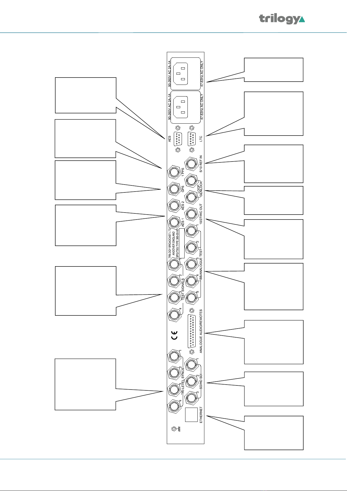
2.5 REAR PANEL CONNECTIONS
AES 1 & 2
out (9 way
Sub-D
female).
LTC 1 & 2 out.
(9 way Sub-D
female).
Mains
input 1
& 2.
Genlock
loop
input.
Option
Board 1 –
GPS receiver
antenna
input.
Option
Board 1 –
GPS receiver
1 PPS
output.
AES 1 & 2 un-
balanced
outputs.
5 / 10 MHz
reference
input.
Clock output
(27MHz,
10MHz, AES
Word).
Analogue test /
black burst
outputs 1 – 5.
Option Board 2
(normally
additional SDI
outputs).
Analogue
audio /
remote
connector (25
way Sub-D
female).
SD / HD
SDI video
outputs.
Option Board 3
(normally tri-level
sync outputs).
RJ-45
Ethernet
network
interface.
Page 11 of 84 Trilogy Communications

Mentor XL
2.6 ANALOGUE AUDIO /REMOTE CONNECTOR PINOUT
The chassis is fitted with a fixed D25 socket.
Pin
Description
Notes
1
Fan OK - 1
Pair with 16. Closed if OK.
2
RS422 CTS-
3
RS422 RXD+
or RS232 RX
4
RS422 TXD+
or RS232 TX
5
RS422 RTS-
6
RS422 TXD-
7
GND
8
RS422 RXD-
9
GND
10
+ 12V DC./ 0.3A
Internal 0.5A self-resetting
thermal fuse.
11
Analogue Audio Out 1+
12
Analogue Audio Out 2 +
13
GND
14
Power OK 1
Pair with 15. Closed if OK.
15
Power OK 2
Pair with 14. Closed if OK.
16
Fan OK - 2
Pair with 1. Closed if OK.
17
GPI - Output 1
18
GPI - Input 2
19
GPI - Input 1
20
RS422 CTS+
or RS232 CTS
21
GPI - Output 2
22
RS422 RTS+
or RS232 RTS
23
Analogue Audio Out 1-
24
Analogue Audio Out 2-
25
GND
2.6.1 Remote Connector
2.6.1.1 Serial Communications Port
The serial port is used during manufacturing test and alignment. The port may be configured for
RS232 or RS422 operation from the System menu. The configuration menu is shown in section 8.
2.6.1.2 Analogue Audio Outputs
The Analogue audio output is provided by an independent audio generator.
2.6.1.3 Power Fail Output
This is a status output provided by a single relay contact. During normal operation, the contact is
closed. The unit senses a failure of any internal voltage rail, causing the relay contact to open.
2.6.1.4 Fan Fail Output
This open collector status output indicates correct operation of the internal cooling fan. Open circuit
/ short circuit and stalled fans are detected.
Page 12 of 84 Trilogy Communications
Mentor XL
2.6.1.5 GPI Inputs 1 and 2
The general purpose interface inputs (GPI) 1 and 2 are configured in software, using the menus
described in section 8.1.1, to provide any of the following functions:
•Force free run mode
•Force genlock mode
•Force external 10MHz lock mode
•Step through SDI output 1 test patterns
•Step through SDI output 2 test patterns
•Step through SDI output 3 test patterns
•Step through set-up memory locations
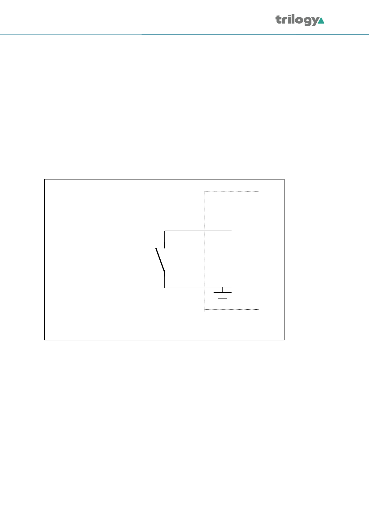
2.6.1.6 Connecting to GPI Inputs
GPI
Mentor XL
Mentor XL GPI inputs
comprise single ended
ground-to-operate inputs.
The inputs can withstand
+/-20V and draw approx.
600uA when operated.
To use a GPI input,
connect the input to the
Mentor XL ground.
Page 13 of 84 Trilogy Communications

Mentor XL
2.6.1.7 GPI Outputs 1 and 2
General purpose interface outputs 1 and 2 are configured in software, using the menus described in
section 8.1.1 to provide any combination of the following functions:
•Loss of genlock input
•Loss of external 10MHz reference
•Line lock error
•Field lock error
•Subcarrier lock error
•Illegal input ScH
•Diagnostic state alert
•Currently locked to external clock reference 5 / 10 MHz
•Currently locked to external genlock
•Currently internal/free-run mode
By combination it is intended that the output can be asserted when one or more conditions is true
(for example, loss of genlock input and/or line lock error).
2.6.1.8 Connecting to GPI Outputs
LOAD
PSU
Mentor XL
GPIO
+
-
GPI outputs comprise single ended
open collector outputs with a 30V /
190mA rating, 600mW dissipation.
To use an output, a load should be
connected between the output and
an external power supply, with the
negative end of the power supply
connected back to the ground pin on
the D type. As an alternative to an
external power supply, a +12V, 300
mA feed is available on pin 10 of the
D25 connector.
Page 14 of 84 Trilogy Communications

Mentor XL
2.7 AES
The chassis is fitted with a fixed D9 socket.
Pin
Description
1
AES 1 +
2
AES 1 -
3
Shield
4
n/c
5
0V GND
6
Shield
7
AES 2 +
8
AES 2 -
9
Shield
A parallel, unbalanced output for each AES signal may be provided on rear panel BNC connectors as
an option.
2.8 LTC
The chassis is fitted with a fixed D9 socket.
Pin
Description
1
LTC 1 +
2
LTC 1 -
3
Shield
4
n/c
5
0V GND
6
Shield
7
LTC 2 +
8
LTC 2 -
9
Shield
2.9 ETHERNET
The Mentor XL is equipped with a 10/100 Base-T Ethernet port. This port may be configured for
either dynamic (DHCP) address mode, or static address mode. These options are located in the Setup
menu. The Mentor XL should be connected to the network in the same way as any other networked
device (e.g. computer or laptop) using a 1:1 CAT 5 RJ45 cable (not provided).
If connected directly to a computer or laptop, either a crossover or straight through style Ethernet
cable may be used.
Page 15 of 84 Trilogy Communications

Mentor XL
3. OPERATION
3.1 FRONT PANEL
SETUP STATUS
Mentor XL
MENTOR 2 REFERENCE GENERATOR
Press STATUS for current configuration
CANCEL ADJUST
O K
ANALOGUE
VIDEO
SDI
AUDIO
MODE
LOCKOPTIONS
Navigation
keys (OK,
cancel, left,
and right).
Rotary
encoder, used
to adjust
values.
Function
key –
SDI video.
Function
key –
audio.
Function
key –
Lock
mode.
Display
status.
Liquid Crystal
Display (LCD)
with 2 rows
each of 40
characters.
Enter
setup
mode.
Function
key –
Option
boards.
Function
key –
analogue
video.
Page 16 of 84 Trilogy Communications
Mentor XL
3.2 POWER ON DISPLAY
When the unit is powered, the LCD will display initialisation messages, as it configures the internal
hardware of the unit. Once initialisation is complete, a message indicating a normal operational
status is displayed, as shown below.
Mentor XL Main Menu
<Digital Video> Analogue Video Audio ->
The top line gives the name of this unit (i.e. Mentor XL). The lower line displays the first available
main menu items.
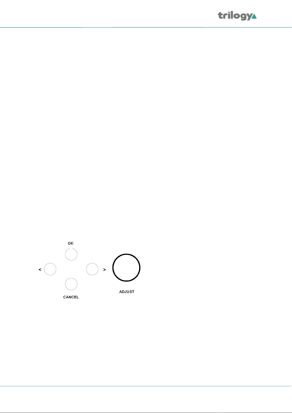
3.3 FRONT PANEL CONTROLS
The panel has four functional areas.
•A Liquid Crystal Display (LCD) used to show information to guide the user through operating the
various functions and show status information
•Front panel buttons:
oLEFT, RIGHT buttons for menu navigation
oOK and CANCEL buttons to execute or exit the currently selected option.
oRotary encoder for parameter adjustment and/or left/right menu navigation
oSDI button to access menus for main board SDI outputs
oANALOGUE VIDEO button to access menus for main board Analogue video outputs
oAUDIO button, to access menus for Analogue audio and AES audio outputs
oOPTIONS button to access option board menus
oLOCK MODE button to configure genlock modes
oSETUP button, for miscellaneous configuration options
oSTATUS button used to access diagnostic and status information
3.4 BASIC OPERATIONAL TECHNIQUE
There are a number of basic concepts, which once appreciated, will simplify the use of the
Mentor XL.
Valid button pushes are indicated by a lamp lit in a button. In most cases, buttons without a lamp lit
will not be prohibited, allowing rapid changes between functions of different types.
Invalid button pushes will result in an informative message on the LCD.
Page 17 of 84 Trilogy Communications

Mentor XL
3.5 SELECTING A FUNCTION
To change any parameter, the appropriate function button must first be pushed. Once a function
button is pushed, that button will illuminate to provide a reminder of which function is active.
Pushing a function button that has sub-functions under the first menu will cause the bottom row of
the LCD to show the lower level functions.
To choose which of these sub-functions is required, the encoder or left – right keys may be used to
step between the sub-functions. The current selection is marked with chevron symbols < >.
The top row of the LCD provides a fuller explanation of the function.
Once the required sub-function is selected, the OK button is used to choose it. Depending on the
sub-function chosen, either a further set of sub-functions or the current value of that function is
displayed. Where appropriate, the currently active option is indicated by square brackets (e.g. [ON]).
If the active option is also selected, it is indicated by asterisks (e.g. *ON*).
3.6 CHANGING VALUES
To change a setting, the encoder control or left – right buttons may be used.
In the case of numerical values there are two functional modes. If the overall range of adjustment is
small the encoder always alters the value by the smallest possible amount. If a wider range of
adjustment is required, a “Delta value” system is used. Use the left/right buttons to switch between
the setting and delta values and use the rotary encoder to adjust the selected value.
As the parameter is changed, the new value will be shown on the LCD. For some functions the unit
responds by altering that value immediately - it is not necessary to confirm or otherwise activate the
change. Otherwise the new value is applied when the OK button is pressed.
3.6.1 Leaving the Selected Function
Once the parameter has been set the unit can be returned to its normal operating mode, or another
function chosen by one of three methods.
Pressing the current (lit) function button will step up through the menu structure one level at a time.
Thus another parameter related to that function button may be changed without having to start
again at the top-level menu.
The OK button allows you to descend the menu structure and the current Function or CANCEL key
allows you to ascend the menu structure.
At any time, any other function button may be pressed to access a different menu. For example,
having set an OUTPUT CONTROL function, the SETUP key may be pushed without having to first step
back up through the menus.
Page 18 of 84 Trilogy Communications

Mentor XL
3.7 MENU TIMEOUT
There is an in-built time-out mechanism that will automatically step back up through the menu
structure one level at a time, until the top level is reached, if a key is not pressed within a
pre-set time period.
The option to configure this feature is located under the Setup >> More >> Display >> Menu Timeout
menu.
3.8 FRONT PANEL LOCK
Front panel controls may be locked to prevent inadvertent changes of settings. To lock or unlock the
controls, press the LEFT and RIGHT buttons simultaneously.
Page 19 of 84 Trilogy Communications

Mentor XL
3.9 TOP LEVEL MENU
The top level menu currently holds these branches:
Home: Top Level
Digital Video
Analogue Video
Audio
Lock Mode
Setup
Status
Options
The content and features of each branch are explained briefly below: a more detailed view of each
section is provided in later sections of this manual. Note that the Options branch (above) is only
displayed if hardware option modules have been installed.
3.9.1 Digital Video
The SDI menu provides full control of the configuration of each of the three SDI outputs. The video
standard, timing and appearance of each output are controlled from this sequence of menus. In
addition, the embedded AES audio is enabled and configured for each output. If the high definition
(HD) option is activated, additional choices will appear on this menu. For more details, see section 4.
3.9.2 Analogue Video
The video menu controls the format of the five Analogue video signals provided on the Mentor XL.
These are arranged as a group of three plus a second group of two outputs. This allows, for example,
the group of three to be set as RGB or YUV in a single operation. See section 5.
3.9.3 Audio
The audio menu controls both non-embedded AES and Analogue audio outputs. For all outputs,
control of frequency and amplitude is available. In addition, for each AES output, the sample rate
and source ident may also be configured. See section 6.
3.9.4 Lock Mode
The genlock input menu sets the required format of the incoming video signal and defines the
behaviour of the Mentor XL when the genlock signal is applied, or removed. See section 7.
Page 20 of 84 Trilogy Communications
Table of contents
Popular Inverter manuals by other brands

EmergoPlus
EmergoPlus PowerXtreme XS20s user manual

Pyle
Pyle PNV2000 owner's manual

Hitachi
Hitachi WJ200 Series Software Quick reference guide

Ningbo Ginlong Technologies
Ningbo Ginlong Technologies Solis 4G User's installation and operation manual

AERMEC
AERMEC VED 030 I Technical manual

TWERD Power Electronics
TWERD Power Electronics PS100-PV user manual


