TWERD Power Electronics PS100-PV User manual

TWERD
®
Renewable Energy Sources
One-phase
photovoltaic and wind inverters
PS100-PV
PS100-WT
PS100-H
1 kW, 3 kW, 5.5 kW
On-Grid / Off-Grid
Photovoltaic systems (PV)
Wind turbine systems (WT)
Hybrid systems: (H)
User manual
Ver. 8,1
www.twerd.pl


Contents
1. Dev ce descr pt on...................................................................................................................................... 5
2. Cond t ons of safe operat on..................................................................................................................... 6
2.1. Warnings............................................................................................................................................... 6
2.2. Basic r les............................................................................................................................................ 6
2.3. Protection against electric shock.......................................................................................................... 7
2.4. Operation list after receiving the device................................................................................................7
2.5. Environmental conditions...................................................................................................................... 7
2.6. Recycle................................................................................................................................................. 7
3. Spec f cat on............................................................................................................................................... 8
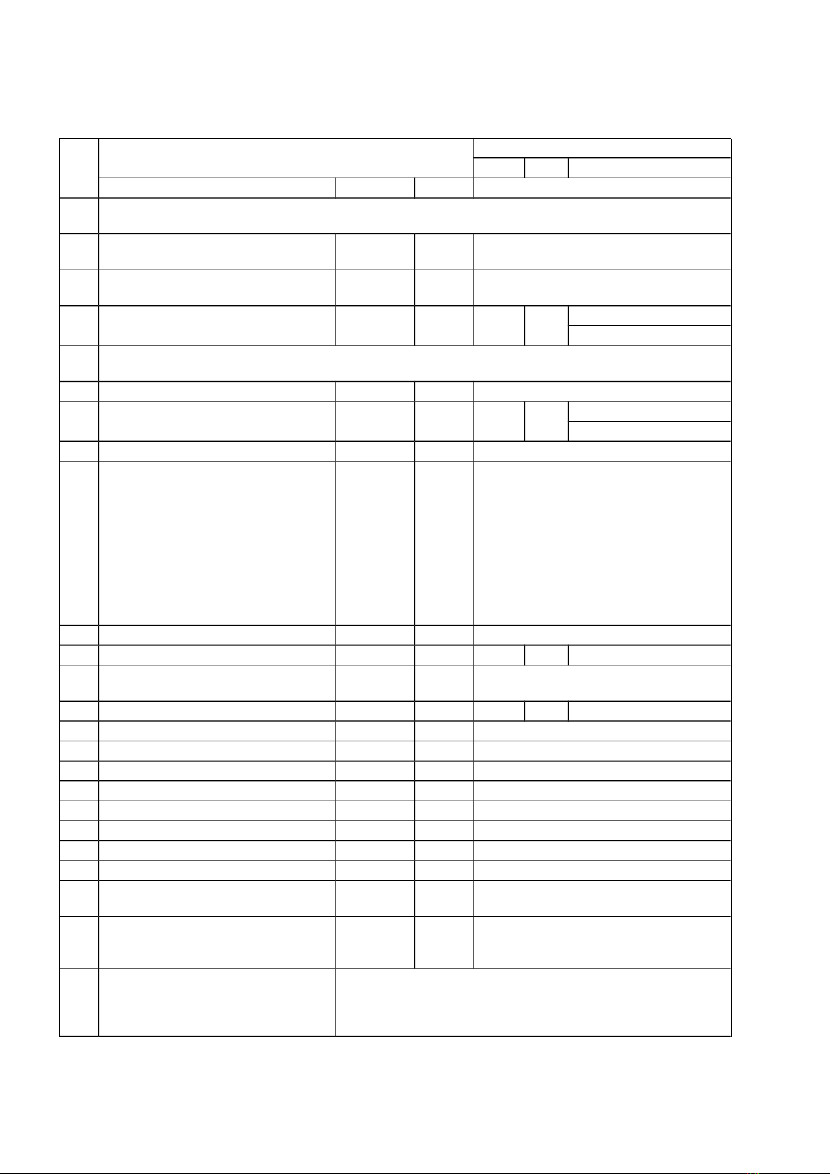
3.1. Technical data....................................................................................................................................... 8
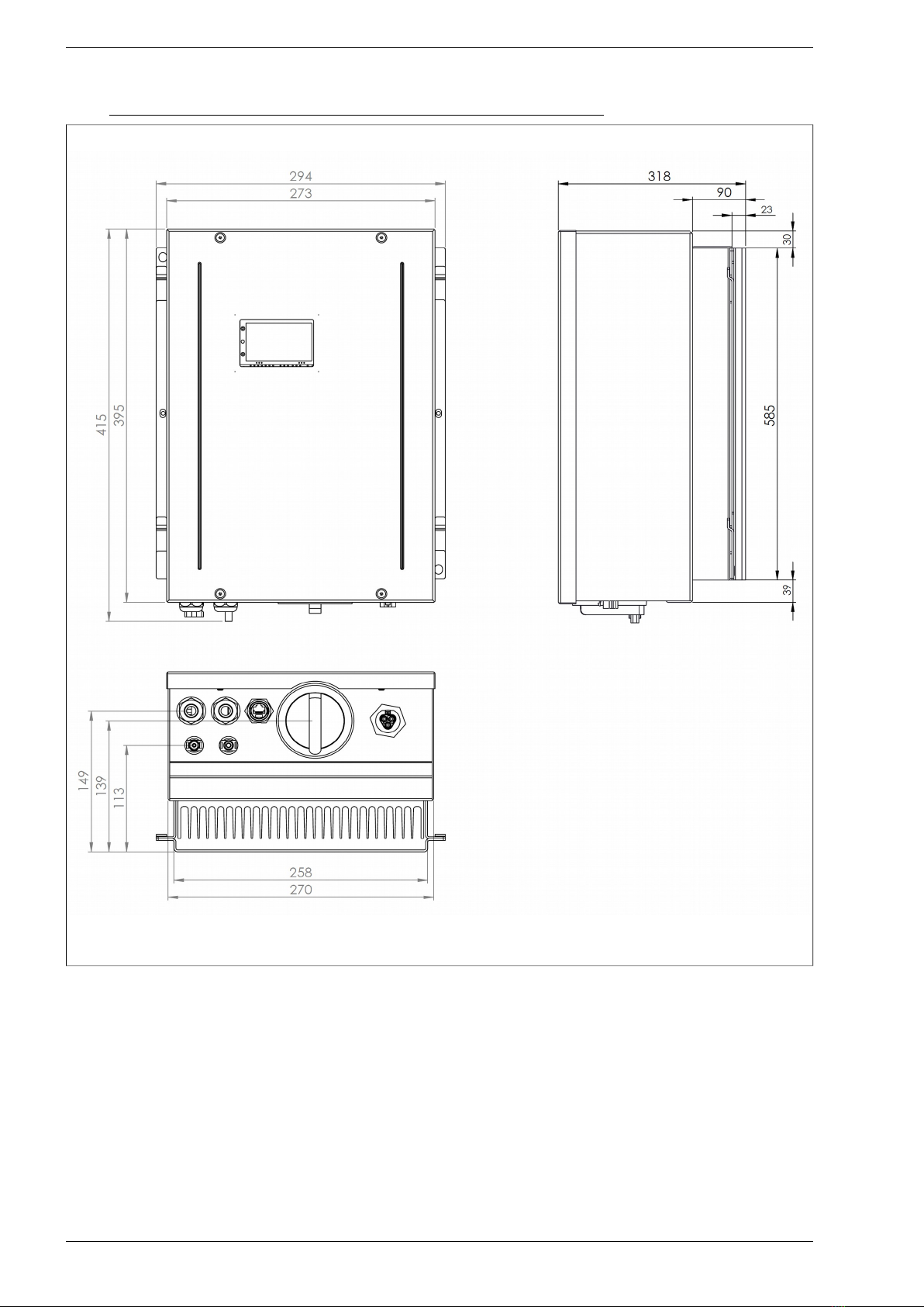
3.2. Mechanical dimensions and weight....................................................................................................10
3.2.1. PS100-WT/1kW, PS100-WT/3kW, PS100-PV/1kW, PS100-PV/3kW.........................................10
3.2.2. PS100-PV/5.5kW, PS100-WT/5.5kW, PS100-H/3kW, PS100-H/5.5 kW.....................................12
3.2.3. PS100-WT+BC/1kW, PS100-WT+BC/3kW, PS100-PV+BC/1kW, PS100-PV+BC/3kW.............14
3.2.4. PS100-WT+BC/5.5kW, PS100-PV+BC/5.5kW, PS100-H+BC/3kW, PS100-H+BC/5.5kW..........16
4. Prepar ng for nstallat on......................................................................................................................... 18
4.1. Inverter installation location................................................................................................................18
4.2. Environmental condition......................................................................................................................18
4.3. Cooling................................................................................................................................................ 18
4.4. Use of resid al c rrent devices........................................................................................................... 18
4.5. Power line connector.......................................................................................................................... 19
4.6. Installation position.............................................................................................................................21
4.7. Power circ it terminals........................................................................................................................22
5. ON-GRID nstallat on................................................................................................................................ 23
5.1. Inverter with WT generator inp t.........................................................................................................24
5.2. Inverter with PV inp t.......................................................................................................................... 25
5.3. Hybrid inverter with AC (PMSG) and DC (PV) inp ts..........................................................................26
6. OFF-GRID nstallat on............................................................................................................................... 27
6.1. Inverter with the WT generator inp t................................................................................................... 28
6.2. Inverter with PV photovoltaic panels inp t..........................................................................................29
6.3. Hybrid inverter with WT generator and PV photovoltaic panels inp ts................................................30
7. Bu lt- n control panel................................................................................................................................ 31
7.1. Information displayed on the operator panel witho t removing the inverter cover.............................32
7.2. Operating the control panel sing b ttons..........................................................................................33
7.3. Updating the Control panel software...................................................................................................35
8. The f rst run............................................................................................................................................... 37
8.1. Maxim m Power Point Tracking (MPPT) and Global Maxim m Power Point Tracking (GMPPT)......37
8.2. 16 point load characteristic of a synchrono s generator.....................................................................38
8.3. Start/Stop command........................................................................................................................... 38
8.4. D mp load resistors............................................................................................................................ 39
8.5. The internal process of switching ON the inverter in on-grid mode.....................................................39
8.6. The internal process of switching the inverter off-grid.........................................................................39
9. D g tal nputs and outputs........................................................................................................................ 40
9.1. Generator load control........................................................................................................................ 41
9.2. Anemometer....................................................................................................................................... 42
9.3. Storm Protection................................................................................................................................. 42
9.4. Remote O tp t Stop Order................................................................................................................. 42
10. Commun cat on parameters sett ng......................................................................................................43
10.1. Connecting the inverter to the Internet.............................................................................................44
10.2. Comm nication via Json file............................................................................................................44
PS100 – User’s man al 3

11. Inverter Mon tor ng System v a “www. nverters.pl”.............................................................................45
11.1. Creating an ser acco nt.................................................................................................................. 45
11.2. Login................................................................................................................................................. 45
11.3. Adding the inverter to the system to monitor its operation.................................................................45
11.4. Acco nt Settings............................................................................................................................... 47
12. Battery charger module.......................................................................................................................... 49
12.1. General information.......................................................................................................................... 49
12.2. Possible operation scenarios............................................................................................................ 51
13. Groups of parameters............................................................................................................................ 53
13.1. Inverter stat s parameters – gro p 0................................................................................................53
13.2. Inverter config ration parameters..................................................................................................... 56
GROUP 12 – EN50549 Grid parameters..............................................................................................63
GROUP 99 – Service statistics............................................................................................................. 66
14. Faults....................................................................................................................................................... 67
14.1. List of fa lt codes.............................................................................................................................. 67
14.2. List of battery charger mod le fail re code.......................................................................................69
15. Order ng nformat on.............................................................................................................................. 71
16. Warranty cond t ons............................................................................................................................... 71
Append x A: EU Declarat on Of Conform ty...............................................................................................72
Append x B: PN-EN 50438:2014-02 Declarat on Of Conform ty................................................................73
4 PS100 – User man al

Chapter 1. Device description
1. Dev ce descr pt on
The family of single-phase, high efficiency and transformerless PS100 inverters is designed for work with
small wind t rbines (eq ipped with permanent magnet synchrono s generators) and PV installations, with an
electric power of p to 5.5 kW. These inverters converts the energy obtained from the wind and/or solar
power plant to a single-phase power grid (so-called "on-grid" systems). They operate f lly a tonomo sly.
After being installed by an a thorized person, the ser's role is limited to systematic monitoring of the
device's condition (fail re, flooding, etc.).
Presented PS100 prod cts family incl des the following types of inverters:
•PS100-WT/1kW, PS100-WT/3kW, PS100-WT/5.5kW - inverters with WT synchrono s generators
inp t (AC voltage inp t): designed for a small wind or water t rbines.
•PS100-PV/1kW, PS100-PV/3kW, PS100-PV/5.5kW - inverters with PV inp t(s) (DC voltage
inp t(s)): designed for a photovoltaic panels (PV).
•PS100-H/3kW, PS100-H/5.5kW - hybrid inverters with one WT inp t and one PV inp t enabling
sim ltaneo s connection of PV panels and a synchrono s generator.
Note: the inverter power determines the total input power obtained from both sources – PV panels
and synchronous enerator. Currents and volta es cannot exceed individual input values iven in
Table 3.1 on pa e 8.
•PS100-x-BAT - each of the above types of inverters (WT, PV, H) can be eq ipped with a battery
charging mod le in the 48V DC voltage system. It enables b ilding off-grid island systems and
intelligent energy management in "on-grid" systems. See chapter 12. Battery char er module on
page 49 for more information.
Photovoltaic panels are loaded on the basis of the following MPPT (Maxim m Power Point Tracking)
algorithm, while for synchrono s generators a 16-point characteristic of the generator's inp t c rrent sho ld
be introd ced as a f nction of its freq ency. In addition, load control of a synchrono s generator can be done
by directly setting the load c rrent sing the MODBUS comm nication protocol (RTU, TCP / IP). Each of
these algorithms is designed to optimally se a renewable energy so rce (RES).
Using the MODBUS or Json comm nication protocol, yo can read from the system information abo t:
• c rrent inverter inp t and o tp t voltages and c rrents,
• c rrent o tp t power (home appliances or electrical network),
• energy delivered in the last 24 ho rs,
• information on occ rring fail res.
The system is eq ipped with an extensive diagnostic and protection tools for the inverter and ser. The
device is sec red:
• from the mains side:
◦ protection against improper mains parameters: voltage, freq ency,
◦ protection against off-grid island operation (disconnection by relays from the network in the
event of its loss);
• from the generator side: overvoltage, overc rrent, before the generator r ns away;
• from the PV side: overvoltage, overc rrent;
• against too high inverter’s heat sink temperat re;
• against too deep discharge of the energy storage (applies to systems with a battery charging
mod le marked "+ BAT").
L m tat on of l ab l ty
Despite all efforts and d e diligence, the Zakład Energoelektroniki TWERD (TWERD Power Electronics)
does not g arantee that the p blished data is free of errors. In case of any do bts or the desire to obtain
additional information, please contact s. All trademarks sed are the property of their respective owners.
PS100 – User man al 5

Chapter 2. Conditions of safe operation
2. Cond t ons of safe operat on
Before start to work with the PS100 inverter read caref lly this User’s man al. Not knowing or ignorance of
the information contained in it can ca se physical inj ry, death or damage to the inverter.
In the f rther part of this User man al, the PS100-WT inverter, to which this instr ction applies, will also be
referred to as the „PS100-WT or "device".
RISK OF ELECTRIC SHOCK HOT SURFACE
2.1. Warn ngs
• Incorrect installation, sing, and maintenance of the device can ca se physical inj ry or death, or
damage to the device and connected eq ipment.
• Some ho sing components, incl ding a heat sink, can get hotter than 80°C d ring normal operation -
there is a risk of b rns.
• Installation, sing, and maintenance of the device m st be performed only by q alified personnel.
• Before switching on the voltage, make s re the device has been correctly installed and all ho sing
elements have been properly assembled.
• After connecting the device to the s pply voltage its internal components (witho t the control
terminals – Fig. 9.1 on page 40) are on the power s pply potential. To ching these components can
ca se an electric shock.
• The device contains DC-link circ it capacitors that can remain charged even when the device is not
powered. It can ca se an electric shock. The time req ired for self-discharge of capacitors in an
ndamaged device is s ally less then 5 min tes. Before starting any installation works wa t 5
m nutes after disconnecting all power s pplies so rces and make s re that a voltage on a clamps is
not present.
Attent on! The lack of the voltage at the connection terminals is not synonymo s with the lack of
dangero s voltage in the internal DC-link circ it of the device.
• Don’t make any connections changes when the device is connected to the power s pply.
• D e to the se of a transformer-free topology of the charger, and th s connecting the negative pole
of the battery bank to the inverter's intermediate circ it, there are dangero s voltage and life-
threatening voltage on the terminals of the battery bank. It is forbidden to to ch the terminals of the
battery bank, beca se it may ca se an electric shock!
2.2. Bas c rules
• The inverter m st not be switched on to work with a synchrono s generator (versions WT and H)
witho t load resistors, as this may ca se t rbines to r n, and conseq ently damages for which the
man fact rer is not responsible.
• Do not make any connections when the electrical voltage is s pplied to the inverter: from the mains
side, photovoltaic panels, wind t rbine generator, battery bank.
• Don’t meas re the voltage end rance of any nit devices.
• To meas re the cables ins lation it is necessary to disconnect them from the device.
• Don’t to ch integrated circ its and any other parts on the device’s electronic board, as they can be
damaged by electrostatic discharge.
• Ens re that no other passive components, s ch as resistors, capacitors, or coils, are connected to
the power cables.
• Any modifications or self-repairs of the device can ca se physical inj ry or death, or damage to the
device and connected eq ipment. Any attempt at self-repair will void any warranty.
6 PS100 – User man al

Chapter 2. Conditions of safe operation
• After disassembling the front cover of the inverter, access to the b ttons of the operator panel and
sim ltaneo sly to the elements that are, nder the conditions of normal operation of the inverter,
nder the electrical voltage dangero s for life and health (active parts) are obtained.
ATTENTION: Take partic lar care d e to the possibility of electric shock. Removing the front cover of
the inverter (when the electrical voltage is s pplied to the device both from the network side and the
generator) and changing the settings can only be made by a person with appropriate electrical
q alifications.
• Periodically, yo sho ld check:
◦ Connection of protective cond ctors,
◦ Wiring (the connections, ins lation),
◦ Did not water get inside the system,
◦ Degree of heat sink dirtiness.
2.3. Protect on aga nst electr c shock
Protective cond ctor m st be connected to inverter’s PE terminal on terminal strip.
The dev ce has bu lt- n protect on aga nst earth fault currents, but t only protects the dev ce and
does not protect the user aga nst electr c shock.
2.4. Operat on l st after rece v ng the dev ce
• After npacking the device, it is necessary to check p vis ally presence of damages which co ld
arise d ring the transport.
• Check p the correspondence between the delivered freq ency converter and the order - check p
the ratings plate on the case.
• Check p the correspondence between conditions in which the converter will be sed and conditions
of an environment for which it is designed.
• Installation of the freq ency converter sho ld be made according to principles of safety and EMC
r les.
2.5. Env ronmental cond t ons
a. Degree of poll tion
D ring design second degree of poll tion has been ass med, at which there are normally only non-
cond cting poll tion. However there is a probability of temporary cond ctivity ca sed by a condensation,
when the device is disconnected from the voltage so rce.
In case the environment in which the device will work, contains poll tion which can infl ence its safety, it
is necessary to apply appropriate co nteraction, sing, for example, additional cases, air channels, filters etc.
b. Climatic conditions
Table 2.1. Installation, wareho sing and transport conditions
Installat on s te Dur ng warehous ng Dur ng transport
Temperature -10 ºC .. +40 ºC -25 ºC .. +55 ºC -25 ºC .. +70 ºC
In protect ve pack ng
Relat ve hum d ty 5 % .. 95 % 5 % .. 95 % Max 95 %
Short-term, insignificant condensation on the external side of the device case is
permitted only when the device is disconnected from the voltage so rce.
A r pressure 86 kPa .. 106 kPa 86 kPa .. 106 kPa 70 kPa .. 106 kPa
2.6. Recycle
Always ret rn yo r sed electronic prod cts, batteries, and packaging materials to dedicated
collection points. This way yo help prevent ncontrolled waste disposal and promote the
recycling of materials.
PS100 – User man al 7

Chapter 3. Specification
3. Spec f cat on
3.1. Techn cal data
Table 3.1. PS100 inverters technical data
Type PS100
No. 1kW 3kW 5.5kW
Descr pt on Name Un t
1 WT inp t (AC voltage): permanent magnet synchrono s generator
PS100-WT, PS100-H inverters
1.1 Working voltage range
from the AC generator side
Ugen V 3 x 60..290 V AC
(Phase - Phase)
1.2 Rated voltage from the AC generator
side
Ugen-n
(n* nominal)
V 3 x 230 V AC
1.3 Maxim m inp t c rrent
from the AC generator side
Igen-max A 7A 13A PS100H/5.5kW: 13A
PS100WT/5.5kW: 24A
2 PV inp ts (DC voltage): photovoltaic panels
PS100-PV, PS100-H inverters
2.1 Voltage range from the PV side Upv V 60..450 V DC
2.2 Maxim m c rrent of PV panels Ipv-max A 9A 13A PS100H/5.5kW: 13A
PS100PV/5.5kW: 2x13A
2.3 Type of PV connector - - MC4
3 N mber of PV and WT inp ts - pcs. PS100-PV/1kW, PS100-PV/3kW:
1 x PV inp t - PV1
PS100-PV/5.5kW:
2 x PV inp t - PV1, PV2
every input has individual MPPT
al orithm
PS100-WT/xkW:
1 x WT inp t
PS100-H/xkW:
1 x PV(PV1) inp t + 1 x WT inp t
4 Efficiency (at rated o tp t power) ƞ % 97%
5 Nominal AC o tp t power Pn kW 1 3 5.5
6 O tp t voltage
(from the power grid side)
Uo t V 1 x 230V, 50Hz
7 The maxim m o tp t c rrent Io t A 4,5 13 25
8 C rrent THD % < 3
9 Work modes - - On-Grid, Off-Grid
10 Nominal voltage of DC-link circ it Udc V 380V
11 Maxim m voltage of DC-link circ it Udc-max V 600V
12 Transistors switching freq ency fsw kHz 16
13 Maxim m temperat re of heatsink Trad-max oC 85
14 Comm nication - - Ethernet, RS485
15 Digital inp ts DI1..DI5 pcs. 5
16 Relay o tp ts: 2A 230V AC K1
K2, K3
pcs. K1: Switchable, 2A 230V AC
K2, K3: Normally Open, 2A 230V AC
17 Internal relays controlling the
operation of braking resistors
Inverters PS 100-WT and PS100-H
Rezystory - 30 A, AC1
18 Protections - before r n- p the PMSG,
- before too high device temperat re,
- the monitoring system of the power grid parameters
8 PS100 – User man al

Chapter 3. Specification
19 Algorithm of Maxim m Power Point
Tracking • WT synchrono s generator inp t (AC): characteristic
I en=f(f en) defined by ser.
• PV inp t (DC): advanced MPPT global tracking system that
g arantees finding the optimal operating point even with
partially shaded or in series-connected panels.
20 Power cons mption in standby mode - W 2
21 H midity - % 85% for 40oC
22 Ambient temperat re range - oC -10ºC..+40ºC
23 IP protection - - IP65
24 Weight - kg Look at the chapter 3.2 Mechanical
dimensions and wei ht on page 10.
Devices with battery char er module
25 Nominal voltage of battery Ubat-n V 48 Vdc
26 Nominal charging/discharging
c rrent
Ibat-max A 50 Adc
PS100 – User man al 9

Chapter 3. Specification
3.2. Mechan cal d mens ons and we ght
3.2.1. PS100-WT/1kW, PS100-WT/3kW, PS100-PV/1kW, PS100-PV/3kW
F g. 3.1. Mechanical dimensions of the inverter
Weight of the inverter with mo nting frame: 14 kg.
10 PS100 – User man al

Chapter 3. Specification
Rys.3.2. Mechanical dimensions of the mo nting frame
IN +
PV
IN -
ROZŁĄCZNIK PV
ps100-20-1
F g. 3.3. Inverter view from the connectors side
Note: PS100-WT - no PV connectors and a PV switch.
PS100 – User man al 11
PV switch

Chapter 3. Specification
3.2.2. PS100-PV/5.5kW, PS100-WT/5.5kW, PS100-H/3kW, PS100-H/5.5 kW
F g. 3.4. Mechanical dimensions of the inverter
Weight of the inverter with mo nting frame: 16 kg.
12 PS100 – User man al

Chapter 3. Specification
F g. 3.5. Mechanical dimensions of the mo nting frame
F g. 3.6. Inverter view from the connectors side
Note: PS100-WT - no PV1, PV2 connectors and a PV switch;
PS100-H – no PV2 connector.
PS100 – User man al 13
PV switch
PV SWITCH
ps100-20-1
IN1 +
PV1
IN1 -
IN2 +
PV2
IN2 -
IN2 +
IN2 -

Chapter 3. Specification
3.2.3. PS100-WT+BC/1kW, PS100-WT+BC/3kW, PS100-PV+BC/1kW, PS100-PV+BC/3kW
F g. 3.7. Mechanical dimensions of the inverter
Weight of the inverter with mo nting frame: 19 kg.
14 PS100 – User man al

Chapter 3. Specification
F g. 3.8. Mechanical dimensions of the mo nting frame
F g. 3.9. Inverter view from the connectors side
Note: PSW100-WT+BC - no PV connectors and a PV switch.
PS100 – User man al 15
PV SWITCH
IN +
PV
IN -
ps100-22-1

Chapter 3. Specification
3.2.4. PS100-WT+BC/5.5kW, PS100-PV+BC/5.5kW, PS100-H+BC/3kW, PS100-H+BC/5.5kW
F g. 3.10. Mechanical dimensions of the inverter
Weight of the inverter with mo nting frame: 21 kg.
16 PS100 – User man al

Chapter 3. Specification
F g. 3.11. Mechanical dimensions of the mo nting frame
F g. 3.12. Inverter view from the connectors side
Note: PS100-WT+BC - no PV1, PV2 connectors and a PV switch;
PS100-H+BC – no PV2 connectors.
PS100 – User man al 17
ps100-23-1
PV SWITCH
IN1+
PV1
IN1+
IN2+
PV2
IN2+

Chapter 4. Preparing for installation
4. Prepar ng for nstallat on
4.1. Inverter nstallat on locat on
• The inverter is s itable for installation indoors and o tdoors.
• The inverter has an IP65 protection rating and this sho ld be taken into acco nt when selecting the
mo nting location.
• In order to minimise the heating p of the inverter, do not expose it to direct s nlight. Install the
inverter in a protected location.
• The inverter m st not be installed or sed at altit des above 2500 m n.p.m.
• All inverters are design to be d st-tight. However, in areas with a heavy b ild- p of d st, the thermal
efficiency may still be impaired by d st forming on the cooling s rfaces. Reg lar cleaning is
necessary in s ch sit ations. It is therefore not recommended to mo nt the device in rooms or areas
in which a strong formation of d st is expected.
• Do not install the inverter in:
◦ flammable or explosive atmosphere beca se it co ld ca se fire or explosion,
◦ areas where ammonia, corrosive vapo rs, acids or salts are present (e.g. fertiliser stores,
ventilation openings from cattle sheds, chemical plants, tanneries, etc.),
◦ places where there is an increased risk of damage from farm animals (horses, cattle, sheep,
pigs, etc.),
◦ stables or adjoining areas,
◦ storage areas for hay, straw, chaff, animal feed, fertilisers, etc.,
◦ greenho ses,
◦ storage or processing areas for fr it, vegetables or winegrowing prod cts,
◦ places sed to prepare grain, green fodder or animal feeds.
• D e to the low noise generated by the inverter in certain operating conditions, staying for a long time
can be slightly b rdensome for some people, so installation in the immediate vicinity of living
q arters is not recommended.
4.2. Env ronmental cond t on
The PS100 inverter sho ld work in dry rooms with little d st. Ambient temperat re sho ld not exceed 40oC
and relative h midity 85% according to Table 2.1 on page 7.
4.3. Cool ng
In order to ens re the req ired air circ lation, the inverter sho ld be mo nted so as to keep a free space of
at least 20 cm from the top and bottom and 10 cm from both sides. When installing in a closed enclos re,
se ventilation openings. It is advisable to se an additional fan. Prevent d st from settling on the heat sink
s rface. The radiator sho ld be cleaned from time to time.
4.4. Use of res dual current dev ces
D e to the b ilt-in RFI filter, the resid al c rrent m st be at least 200 mA.
18 PS100 – User man al

Chapter 4. Preparing for installation
4.5. Power l ne connector
The inverter contains a connector for connecting the inverter to an 230 V, 50 Hz electricity network.
The terminals on the connector are marked as follows: L and N. The PE terminal is marked with the earth
symbol .
NPE
L
ps100-30-1
F g. 4.1. View of the mains connector
Remember to carry out voltage-free nstallat on work. Otherw se there s a r sk of electr c shock that
s dangerous to health and l fe.
Pict res 4.2 - 4.4 below show the s bseq ent stages of connector preparation. Pict re 4.5 shows how to
disconnect the connector.
ps100-26.3en
Power supply wire
To the inverter
F g. 4.2. Preparing the connector
PS100 – User man al 19

Chapter 4. Preparing for installation
Tightening tor ue
typ. 4+1 Nm
ps100-27-1en
F g. 4.3. Closing the connector
!
ps100-28-1
F g. 4.4. Connecting the connector to the inverter
Attent on: Fig. 4.3 and 4.4 show connectors for a 3-phase network. However, the principle of mo nting
connectors for the network 1-phase is the same.
20 PS100 – User man al
This manual suits for next models
2
Table of contents
Popular Inverter manuals by other brands

Sinclair
Sinclair SDV6 SCC-61 User and installation manual

LogicPower
LogicPower EA33KTLSI Installation & operation manual

Ampair
Ampair AQUAIR 100 Operation installation and maintenance

Epever
Epever UP2000-HM6022 user manual

Mitsubishi Electric
Mitsubishi Electric FR-CS84-012 instruction manual

Omron
Omron V7-IP65 quick start guide