Trimline OpalInstallation instruction 3
English
1 GENERAL INSTRUCTIONS
NOTE
The installation may only be carried out by an authorised
person.
•The appliance must be installed, connected, inspected
according to local standards and regulations.
•
roof face must also meet the requirements outlined in
•The temperature of the walls near the side and back of
the appliance may not exceed the ambient temperature
maximum increase of 60 K gives a maximum temperature
of 80 °C.
•The appliance has been approved in combination with
with European CE standards for gas appliances, and may
therefore only be applied with this system.
•
gas distribution (gas type and gas pressure) as indicated
•The instructions are only applicable if the relevant country
code is stated on the appliance.
•
used. The gas supply pipes therefore need to be vented
•Ignite the appliance according to the user manual and check
must be removed from the glass panel using a glass cleaner
Distance to ammable materials
Maintain the following minimum distances from combustible
materials: front 500mm, side 500mm, top 1200mm to curtains,
distance of 50mm from the back wall.
Distance to non-ammable materials
The appliance needs to be placed a minimum distance
of 25mm from the wall unless stated otherwise in these
instructions.
WARNING
•
appliance, the glass panel surface is considered to be an
active zone. The glass panel surface can become very hot.
•Therefore, you should take care by, for example, keeping
children and those requiring help away from the immediate
2 PLACING THE APPLIANCE
NOTE
Before installing the appliance, please read Chapter
8Concentric ue system.
Option
Chapter 11 Installing the optional LED glow bed module.
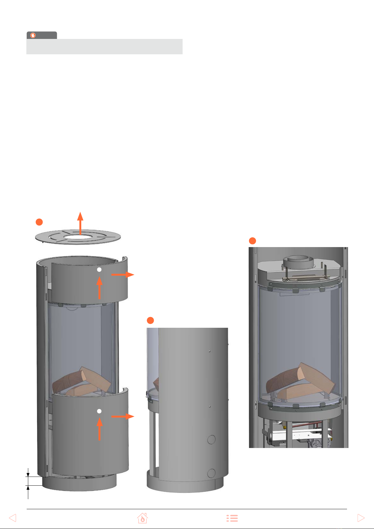
2.1 Preparation and installation
•Check the packaging for damage. Remove the packaging
and check the contents are intact and complete. Report
damage and defects to the supplier immediately.
•The packaging contains the following components:
- Appliance
- Remote control
- Ceramic wood set
- dispersion medium
(glass granules and
coal embers)
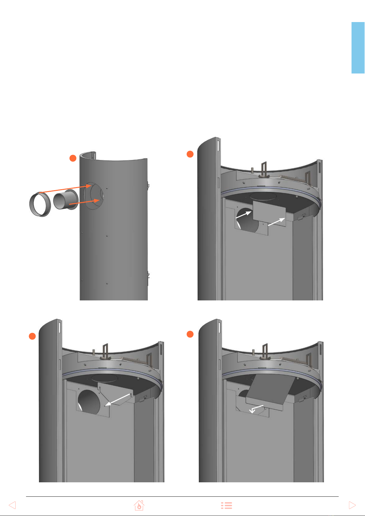
- restrictor
(top connection)
- restrictor
(rear connection)
-
(rear connection)
- 4 x AA battery
- 2 x AAA battery
- Installation instruction
- User Manual
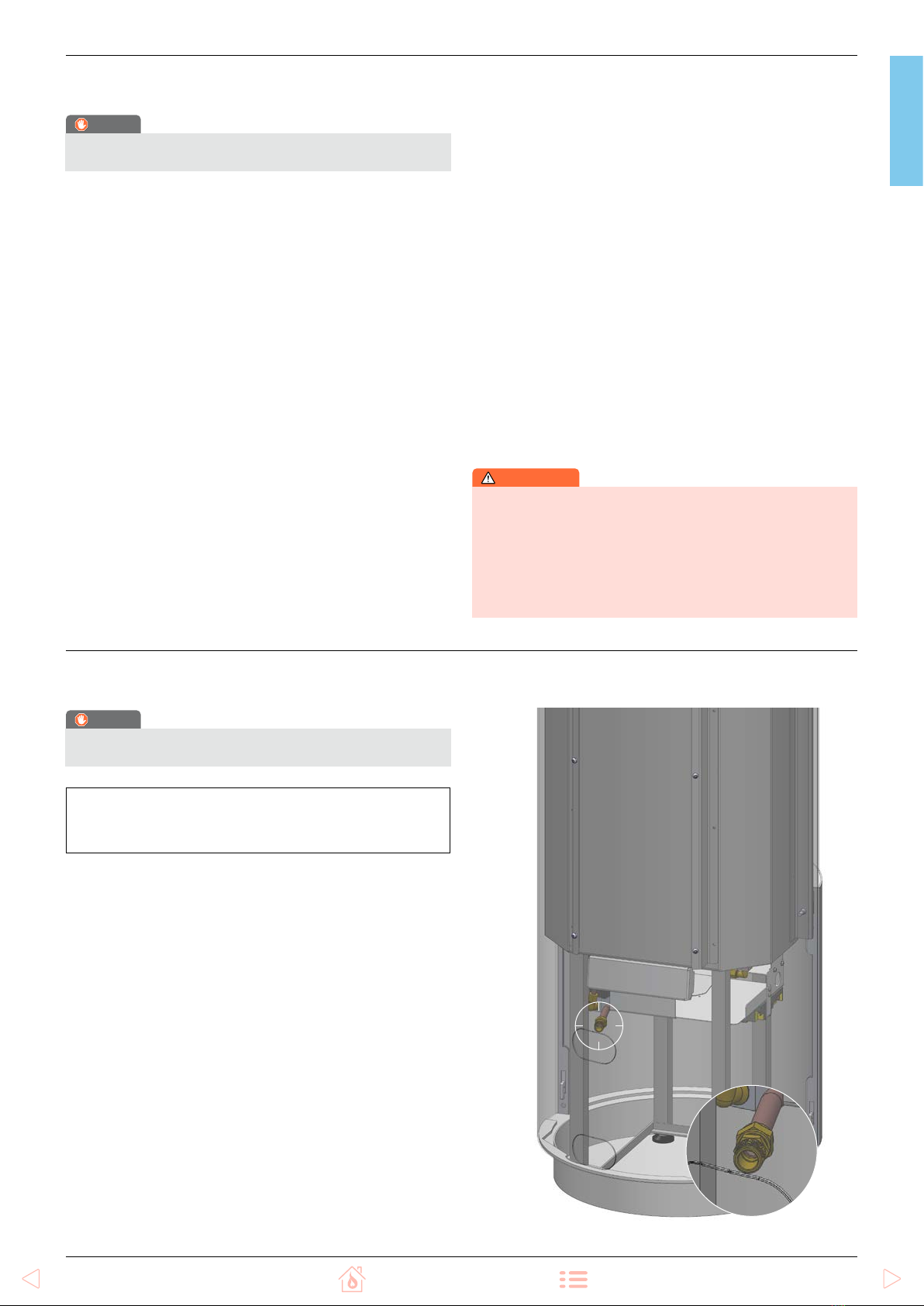
3/8” connection point