15 September 2017
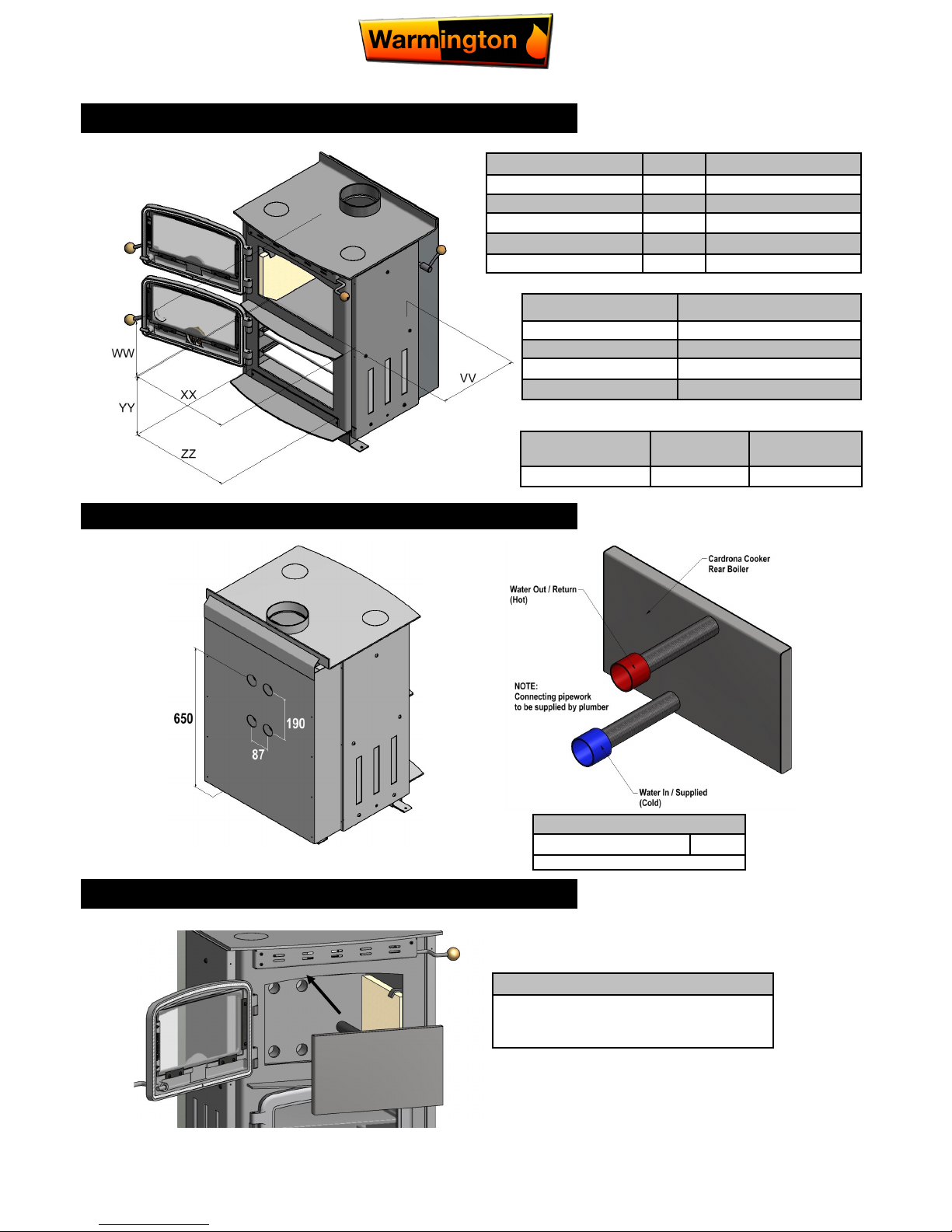
All Dimension are in mm………….Copyright ©
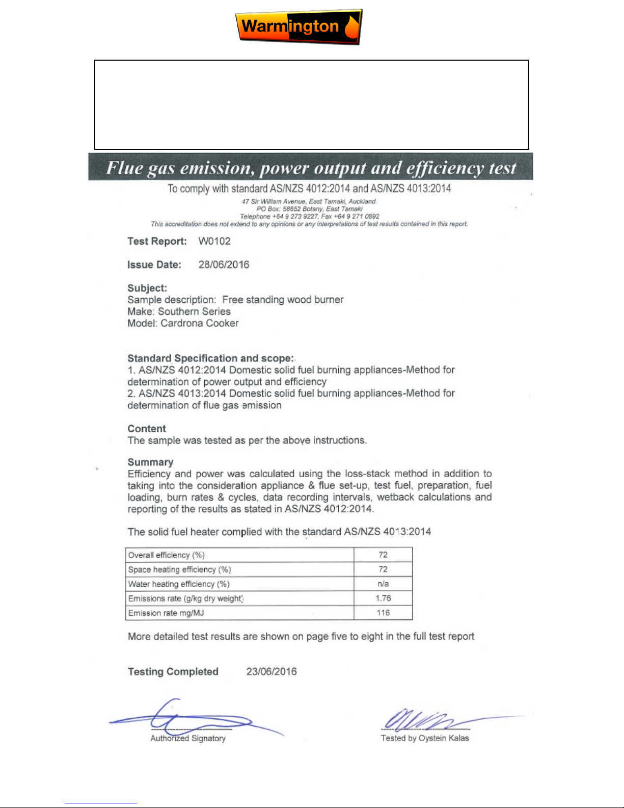
9Due to continued product improvement, Warmington Ind LTD reserves the right to change product specifications without prior notification.
OPERATING INSTRUCTIONS FOR THE OVEN
CLEANING THE CARDRONA COOKER
The Cardrona Cooker should only be cleaned when it is cold. The exterior can be dusted with a firm brush. Do not use a cloth
to clean, as this will drag on the paint finish leaving a lint on the surface.
As the cooking stove top is used for cooking, normal wear and tear will occur. Spills should be mopped up immediately with a
damp cloth, but oven cleaners should not be used as they are too abrasive.
The exterior of the Cardrona Cooker is painted with a high temperature cooking stove paint, and from time to time it may be-
come necessary to renovate the exterior by repainting. The surface must be prepared by rubbing down with a wire brush.
The cooking stove paint will not adhere to the surface if there are fat deposits or food particles on the area to be resprayed.
High temperature cooking stove paint is available from Warmington. Do not use this paint until the Cooker is completely cold
and always follow the instructions on the container before starting to paint.
The glass door should stay relatively clean if the correct type of fuel is used, but from time to time this can be cleaned when
cold with a proprietary glass cleaner and a dry cloth, or depending on the soot build up, a nylon pan scourer.
TEMPERATURE GAUGE REMOVAL TO CLEAN
Step 1:
Open the bottom oven door & loosen glass
bracket with 3mm allen as shown.
Step 2:
Remove temperature Gauge as shown.
The Temperature gauge on the oven door provides an indication of oven
temperature. It should be noted however, that since the Gauge is attached to the
door, temperature may drop if the oven door is left open for a prolonged period of
time, so the oven may be hotter or cooler than indicated by the Gauge.
Once the oven door is closed again the Gauge will come back to temperature.
OPERATION OF THE OVEN TEMPERATURE GAUGE
The oven is heated directly by the fire. In order to heat up the oven, the
fire should be lit as described in our specifications. Once the fire is es-
tablished, pull the oven Damper handle forward. This will allow the hot
fumes from the fire to circulate around the inner cavity thus heating up
the oven.
To maximize the heat from the fire into the home, always operate
the oven heated by having the damper control on the side to the
forward position. To reduce the heat going to the oven, the oven
damper control should be pushed to the upright position backward. This
will allow the hot fumes to escape directly up the chimney, thus reducing
the heat to the oven.
NOTE: Do not run the fire for long periods with the door ajar as
damage may result.
The oven Air Control slider on the oven door will allow small amounts of
air to escape when the Air Control is opened This is a fine adjustment
only, & you will find that in time operating the firebox wood load, oven
Damper Control & the oven Air Control slider together, you will get the
desired heat.