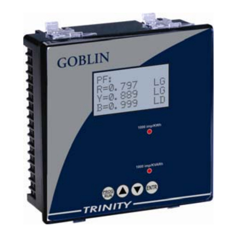
Trinity ACCUVAR User manual

pg. 1
TRINITY

pg. 2
TRINITY
ACCUVAR - Operational Manual
User’s Manual
ACCUVAR
KVAR BASED CONTROLLER FOR LT CAPACITOR BANKS
This document contains the latest technical information about ACCUVAR which is a
microcontroller based KVAR controller for LT capacitor bank. The product,
ACCUVAR is sophisticated electronic equipment and, the user is advisedto read this
User’s Manual carefully before attempting to install or operate the equipment.
Published on: 01.11.2021
Document Version: 2.0

pg. 3
TRINITY
ACCUVAR - Operational Manual
Warranty Statement
Trinity warrants to the original retail purchaser of the Trinity product
enclosed with this limited warranty statement that the product, if
purchased new and used in the India conforms to the manufacturer’s
specifications and will be free from defects in workmanship and materials
for a period of one year from the date of original purchase, unless
expressly stated otherwise by Trinity, in a written format. Should your
Trinity product prove defective during the warranty period, please bring
the product securely packaged in its original container or an equivalent,
along with proof of the date of original purchase, to our Trinity Dealer or
Factory. You are responsible for all costs (shipping, insurance, travel time)
in getting the product to the service location. Trinity will, at its option, repair
or replace on an exchange basis the defective unit, without charge for
parts or labor. When warranty service involves the exchange of the
product or of a part, the item replaced becomes Trinity property. The
replacement unit may be new or refurbished to the Trinity standard of
quality, and at Trinity’s option, the replacement may be another model of
like kind and quality. Trinity’s liability for replacement of the covered
product will not exceed the original retail selling price of the covered
product. Exchange or replacement products or parts assume the
remaining warranty period of the product covered by this limited warranty.

pg. 4
TRINITY
ACCUVAR - Operational Manual
What This Warranty Does Not Cover:
This warranty does not apply to refurbished or reconditioned products.
This warranty covers only normal use in India. This warranty does not
cover damage to the Trinity product caused by parts or supplies not
manufactured, distributed or certified by Trinity. This warranty is not
transferable. This warranty does not cover third party parts, components
or peripheral devices added to the Trinity product after its shipment from
Trinity. Trinity is not responsible for warranty service should the Trinity
label or logo or the rating label or serial number be removed or should the
product fail to be properly maintained or fail to function properly as a result
of misuse, abuse, improper installation, neglect, improper shipping,
damage caused by disasters such as fire, flood, and lightning, improper
electrical current, interaction with non-Trinity products, or service other
than by a Trinity Authorized Service.
The warranty and remedy provided above are exclusive and in lieu of all
other express or implied warranties including, but not limited to, the implied
warranties of merchantability or fitness for a particular purpose. In the
event, the remedies above fail, Trinity’s entire liability shall be limited to a
refund of the price paid for the Trinity product covered by this limited
warranty. Except as provided in this written warranty, neither Trinity
Energy Systems Pvt. Ltd. nor its affiliates shall be liable for any loss,
inconvenience, or damage, including direct, special, incidental, or
consequential damages, resulting from the use or inability to use the
Trinity product, whether resulting from breach of warranty or any other
legal theory.

pg. 5
TRINITY
ACCUVAR - Operational Manual
INDEX
Introduction …………………………………………………………………………………………………..
The Main Features Available in this Model ………………………………………………………..
Technical Specifications …………………………………………………………………………….
Measurement …………………………………………………………………………………….......
Miscellaneous ………………………………………………………………………………………...
Installation and Commissioning……………………………………………………………………………
Back View (Connection Scheme) of the Unit…………………………………………………………….
Capacitor Panel Connection Scheme………………………………………………………………
Operational Details…………………………………………………………………………………………..
Programming Mode………………………………………………………………………………...............
1.Setting Main CT Primary, Main CT Secondary, PT Ratio and Mode of control action…….
2. Setting Capacitor CT Enable, Capacitor CT Primary and Secondary and Desired PF......
3.Setting Switching, Number stages, Meter Address and Baud rate……………………….....
4. Setting operation type, Alarm Mode, Alarm Limit and Alarm Delay………………………...
5. Setting Switch Delay, Damp, Reference Bank number and Auto Phase Input Detection..
6. Setting phase Input sequence for all channels and Minimum Bank………………………..
7. Auto Sense, Setting Minimum operating Current and PF Value to Switch OFF Banks…..
Run Mode ……………………………………………………………………………………………………
Screen Displays………………………………………………………………………………………
Resetting Average PF………………………………………………………………………………..
Freezing and unfreezing the AutoScroll …………………………………………………………...
Control Outputs ……………………………………………………………………………………………...
Troubleshooting ………………………………………………………………………………………
Troubleshooting Guide ………………………………………………………………………………
6
7
8
9
10
11
11
12
13
14
15
15
16
16
17
18
19
20
20
22
22
22
23
25

pg. 6
TRINITY
ACCUVAR - Operational Manual
Introduction:
Every Power distribution system requires reliable metering of various electrical
parameters. From the electricity user's point of view, this is important for saving of
electrical energy, where-ever possible. Not only should his distribution transformer
be loaded optimally, but it should also operate at near unity power factor. The load
imbalance on the three phases should be within reasonable limits. Thus, information
like amount of loading imbalance, power factors at different times of the day, peak
loading hour etc. can be of great help in planning usage of power and also
implementing automatic switched capacitor systems to maintain power factor near
unity. This is where ACCUVAR comes in. ACCUVAR is a KVAR based controller
which controls capacitor banks optimally to achieve near unity power factor and also
which measures/calculates various electrical parameters. ACCUVAR is meant for
use in three phase four wire electrical system. It uses the three watt-meter method
to calculate KVA, KW & KVAR.
ACCUVAR is based on a powerful micro-controller. The controller receives voltage
& current signals and performs high speed measurement and calculations, typically
finishing one complete measurement cycle in less than a second.
The unit displays all parameters locally on a 128 x 64 Display. The user-friendly
keypad on the front makes programming the unit (for C.T. ratios etc.) very easy.
ACCUVAR is thus a very versatile controller and accurate information interface for
the user.

pg. 7
TRINITY
ACCUVAR - Operational Manual
The Main Features Available in this Model
•3P4W electrical system
•Three powers: KW, KVA and KVAR
•Three phase voltages (Vr, Vy & Vb) and currents(Ir, Iy, Ib)
•Auto phase sequence and polarity detection and correction
•Active energy (KWh) and apparent energy (KVAh)
•Capacitor CT sensing enable/disable selection
•CT ratio for both load current and capacitor current selectable
•PT ratio is site programmable
•Capacitor current (I cap)
•Phase-Wise PF, System PF and Average integrated PF
•Autosense/Manual types of KVAr control and the capacitor bank size of every
stage display.
•Eight/twelve/fifteen stage relays controller with a one alarm selectable.
•Up to 15th Odd Harmonics and Total Harmonic Distortion (THD) for each
Voltages and Currents

pg. 8
TRINITY
ACCUVAR - Operational Manual
Technical Specifications
Parameter
Type
Name
Statistics
Supply
Three Phase and Neutral of a 3P4W system
Voltage
Direct Voltage Input : Up to 300V L-N
Burden : 0.5VA
Current
Secondary Current Input : 5A or 1A
CT Ratio : Site Selectable
Range of Reading : 5 - 5000A
Burden : < 1.0VA
Overload : 5A CT = 6A RMS Continuous
: 1A CT = 1.2A RMS Continuous
Power Supply
Self Powered from mains. Wide operating Voltage SMPS:
80 VAC - 480 VAC, 45-65 Hz.
Relay
Switching Voltage : Max. 250 VAC
Switching Power : Max. 1000W
Expected Mechanical Life : >10 x 106switching operations.
Expected Electrical Life : >4 x 10⁶switching operations.
@(Load = 200VA, Cos Ø = 0.5)
INPUT
OUTPUT

pg. 9
TRINITY
ACCUVAR - Operational Manual
Measurement
Parameter
Type
Name
Statistics
Voltage
(Volts L-N: VRN,
VYN, VBN)
Accuracy : 0.5% of Reading
Current
(Amps IR, IY, IB)
Accuracy : 0.25% of Reading
Capacitor Current
CT Ratio : Site Selectable
Accuracy : 1.0% of Reading
Line Frequency
45 to 65 Hz, Accuracy : 0.3% of Reading
Active Power (P)
Accuracy : 1.0% of Reading (For IPFI>0.9)
Reactive Power (Q)
Accuracy : 1.5% of Reading
(Between 0.5 Lag to 0.8 Lead)
Apparent Power (S)
Accuracy : 1.0% of Reading
Power Factor
Accuracy : 1.0% of Reading (IPFI≥0.5)
Range of Reading : 0.05 to 1.00 Lag/Lead
Total Active Energy
(KWh)
Range of Reading : 0 to 9999999.9 KWh
Accuracy : 1.0S as per IS13779.
Total Apparent
Energy
(KVAh)
Range of Reading : 0 to 9999999.9 KVAh
Accuracy : 1.0% of Reading
Total Reactive
Energy (KVARh)
(Lag & Lead)
Accuracy : 1.5% of Reading
Range of Reading : 0 to 9999999.9
Cap. Bank KVAR
True RMS Basic Parameters
Power
Energy
Misc.

pg. 10
TRINITY
ACCUVAR - Operational Manual
Miscellaneous
Parameter
Type
Name
Statistics
Bezel
144 X 144 mm
Panel Cutout
138 X 138 mm
Depth of installation
55 mm
Operating temp
10 0C to 50 0C
Weight
0.82 Kgs (Approx.)
Min. Operating Current
1% or 5% of CT primary for FIFO/SFIFO Mode
Dimensions

pg. 11
TRINITY
ACCUVAR - Operational Manual
Installation and Commissioning
To install and commission the unit, proceed the following instructions:
1. Push the unit into the Panel and mount it by using the clamps provided.
Back View (Connection Scheme) of the Unit
2. Connect the three phases with the phase sequence being R-Y-B to the terminals
marked R, Y and B accordingly such as shown above Connection Scheme. Make sure
that the three phases coming to the unit come through control fuses 1.0 Amp rating.
This will protect the electronics inside from damage due to severe over voltages or
phase faults in the system.
3. Connect the neutral wire to the terminal marked N.
4. Connect the two wires from the R-phase main CT to terminals marked M1 & L1 such
that S1 from CT goes to M1 on the unit. Connect the two wires from the Y-phase main
CT to terminals markedM2 & L2 such that S1 from CT goes to M2on the unit. Connect
the two wires from the B-phase main CT to terminals marked M3 & L3 such that S1
from CT goes to M3 on the unit.

pg. 12
TRINITY
ACCUVAR - Operational Manual
5. Connect the two wires from the Y-phase capacitor CT to terminals marked CM & CL
such that S1 from CT goes to CM on the unit.
6. Switch on the three phases supply. Unit will power on from these three phases supply.
7. First of all, user should program the following parameters of the unit: CT RATIO FOR
MAIN CTs, CT RATIO FOR CAPACITOR CTs, ALARM MODE. Refer Operational
Details in the next section. The proper operation of the relay can commence only after
these three parameters are defined.
8. Ensure that all capacitors are in the circuit i.e. all fuses link pushed in. Give Autosense
(Refer Operational Details in the next section). ACCUVAR will first display
'AUTOSENSING' and as it switches on one bank at a time and also,displays the bank
size of every stage. After AUTOSENSING is completed, the unit will Reset.
9. In case user did not connect proper voltage and current I/p as described in second
point, Phase sequence detection will help. In order to detect proper phase sequence,
the load current should have a value greater than zero. The unit will switch ON and
OFF the bank selected by user in REF_BANK, in order to perform auto correct. If
load is nonlinear or too many sudden changes occur in the load during this process,
it may not be able to correct the connection. In this case, user must disable non linear
load temporarily and repeat the process or can manually enter the phase sequence
value. Make sure to connect three phase capacitor bank on selected REF_BANK
number.
10. Now, the unit is ready for the control action after a 1 minute delay.
Capacitor Panel Connection Scheme

pg. 13
TRINITY
ACCUVAR - Operational Manual
Operational Details
The KVAR Based Controller for LT Capacitor Banks, ACCUVAR is a versatile meter, with all the
features needed to implement a robust electrical load management system. It can be configured
to suit most PF control needs and this is achieved by making as many parameters field
programmable as possible.
There are basically two modes of operation in ACCUVAR:
1. Programming Mode
2. Run Mode
After supplying power (80 VAC - 480 VAC), the unit displays immediately power on display
message and by default, the display comes into Run Mode such as shown below.
Now, the unit can be operated by using the following keypad provided for both the Programming
Mode and Run Mode.
Press key for about five seconds continuously, to go from Run mode to Programming
Mode. The first screen in this mode is:

pg. 14
TRINITY
ACCUVAR - Operational Manual
Programming Mode
In order to set all the field programmable parameters, the user has to press the keys such as,
, , And . Once the display is in Programming Mode,
Press key to set the values for the following parameters:
1. CT Ratio for load current
2. PT Ratio
3. Mode of control action FIFO, SFIFO, PID or VAR
4. Capacitor CT Ratio (If Enable)
5. Desired PF setting
6. Switching (Thyristor or Contactor)
7. Number of Capacitor bank stages
8. Meter Address
9. Baud rate
10. Alarm Mode
11. Alarm limit - PF setting below which alarm will operate
12. Alarm Delay - Delay after which alarm should operate
13. Switching Delay - Delay between two successive switching operation of Relay
14. Damp Factor for settling the sensitivity level for control action
15. Reference Bank number
16. Auto phase input sequence detection
17. phase input sequence setting for all three channels
18. Min bank
19. Auto sense of capacitors
20. Minimum Operating current for FIFO and SFIFO mode
21. PF value to switch OFF banks
,,

pg. 15
TRINITY
ACCUVAR - Operational Manual
1. Setting Main CT Primary, Main CT Secondary, PT Ratio and Mode of control action.
In order to give actual voltage and current values in your system, Main CT Primary and
Secondary as well as PT Ratio should be set. Main CT Primary can be select from 5 to
5000. main CT Secondary can be select 1 or 5. PT Ratio can be select from 1, 3.7727, 4.0,
6.2727, 30, 60, 100, 200, 300, 600 and 1200.
For PF correction, there are four types of Control Action such as VAR, PID, SFIFO and
FIFO which are selectable at site. In case the control action is selected to VAR, Minimum
Bank, Capacitor CT and AUTOSENSING become relevant as programmable parameters.
However, these parameters are not applicable in case of FIFO or SFIFO mode control
action.
To set above parameters, proceed as follows:
Once in Programming mode,
1. Set Arrow (>) to the desired parameters using and keys and press key. Now
Arrow (>) starts blinking which means value of this parameter can be set now. Set desired
value by using and keys and again press key to save its value.
2. If other parameters need to be changed, do so using similar method. Else, press
key for about four seconds continuously. The unit will restart and enter into run mode.
2. Setting Capacitor CT Enable, Capacitor CT Primary and Secondary and Desired PF
In VAR control action mode, using capacitor CT, proper Bank KVAR can be sensed.
Capacitor CT Primary and Capacitor CT Secondary will be enable in case of CAP_CT_ENB
is set to YES. Capacitor CT Primary can be set from 5 to 5000. Capacitor CT Secondary
can be set to 1 or 5. The desired PF can be set to either LEAD or LAG according to user’s
requirement. In case of LAG, the PF could be set from 0.800 to 1.000. In case of LEAD, the
PF could be setting from 1.800 to 1.999. e.g., the PF to be set for 0.998 LEAD should be
set as 1.998.
To set above parameters, proceed as follows:
Once in Programming mode,
1. Set Arrow (>) to the desired parameters using and keys and press key. Now
Arrow (>) starts blinking which means value of this parameter can be set now. Set desired
value by using and keys and again press key to save its value.

pg. 16
TRINITY
ACCUVAR - Operational Manual
2. If other parameters need to be changed, do so using similar method. Else, press key
for about four seconds continuously. The unit will restart and enter into run mode.
3. Setting Switching, Number stages, Meter Address and Baud rate
Normal (Contactor) OR Fast (Thyristor) switching is Site selectable. ACCUVAR supports
up to 15 capacitor bank stages. For user’s system requirement, the number of active
stages can be selected from 2 to 15. This is helpful in cases where the relay has been
purchased for higher number of stages but presently, fewer stages have been actually
connected. The Relay has RS485 port for external communication as an optional feature.
ACCUVAR supports MODBUS-RTU protocol on RS485 port. Each device on RS485 bus
should have unique address for proper functionality. Unit Address value is programmable
from 1 to 255. The baud rate for communication is programmable between 9600 or 19200.
To set the desired PF above parameters,
Once in Programming mode,
1. Set Arrow (>) to the desired parameters using and keys and press key. Now
Arrow (>) starts blinking which means value of this parameter can be set now. Set desired
value by using and keys and again press key to save its value.
2. If other parameters need to be changed, do so using similar method. Else, press key
for about four seconds continuously. The unit will restart and enter into run mode.
4. Setting operation type, Alarm Mode, Alarm Limit and Alarm Delay
If you have Solar panel installation at your site, select Solar else select Normal mode for
proper control action. The relay has an inbuilt alarm mode. In case, the relay ordered is of 8
stage, selecting the alarm mode as NO will keep it as 8 Stage relay. The Control action will
cover 8 Relays. If, however, you have selected alarm mode other than NO, the relay will
effectively become 8+1ALARM stage relay and the 16th stage will be used as an alarm
Contact.

pg. 17
TRINITY
ACCUVAR - Operational Manual
Thus, in a fifteen-stage relay, alarm mode NO means a 15 stage Relay, while alarm mode
other than NO will make it as 15 stage Relay, with 16th stage used as an alarm contact. There
are two additional parameters which need to programmed. i.e. Alarm Limit and Alarm Delay.
In Alarm mode, if the selected parameter remains below/above the Alarm Limit, continuously
for Alarm Delay time, the alarm relay will become ON. The hooter connected to this stage can
be silenced by pressing any key. Alarm Mode can be set on PF, I_THD, V_THD or NO. Alarm
mode PF will cause alarm when PF remains below the limit. For alarm mode I_THD or V_THD,
alarm will occur when the THD values for current/voltage are above the programmed ALARM
LIMIT. The Alarm Limit is programmable from 0.800 to 0.999 for PF Mode. same can be set
between 10 to 80% of V_THD & I_THD. The sign of PF is not considered. Alarm Delay value
can be set from 20 to 180 seconds.
To set the above parameters, proceed the following instructions:
Once in the programming mode,
1. Set Arrow (>) to the desired parameters using and keys and press key. Now
Arrow (>) starts blinking which means value of this parameter can be set now. Set desired
value by using and keys and again press key to save its value.
2. If other parameters need to be changed, do so using similar method. Else, press key
for about four seconds continuously. The unit will restart and enter into run mode.
5. Setting Switch Delay, Damp, Reference Bank number and Auto Phase Input
Detection
Switch Delay is one type of digital dead band. In fast switching mode Value can be set from
1 to 10 and in normal switching mode value can be set from 40 to 120. The Damp value
should be set from 5 to 20 in normal switching mode and 1 to 10 in fast switching mode so
as to slow down the response of the control algorithm. Setting a higher value of DAMP will
slow down the response of the relay to transient jumps in system KVAR values. The unit
will switch ON and OFF the bank number selected by user in REF_BANK, in order to detect
phase sequence of inputs.
NOTE: Make sure to connect three phase capacitor bank on selected REF_BANK number.
Auto phase input detection can use to detect phase sequence error and correct all values
according to detection. In order that this feature works, the load current should have a value

pg. 18
TRINITY
ACCUVAR - Operational Manual
greater than zero. The unit will switch ON and OFF the bank selected by user in
REF_BANK, in order to perform auto correct. If load is nonlinear or too many sudden
changes occur in the load during this process, it may not be able to correct the connection.
In this case, user must disable non linear load temporarily and repeat the process or can
manually enter the phase sequence value.
To change the above parameters, proceed the following instructions:
Once in the programming mode,
1. Set Arrow (>) to the desired parameters using and keys and press key. Now
Arrow (>) starts blinking which means value of this parameter can be set now. Set desired
value by using and keys and again press key to save its value.
2. If other parameters need to be changed, do so using similar method. Else, press key
for about four seconds continuously. The unit will restart and enter into run mode.
6. Setting phase Input sequence for all channels and Minimum Bank
If phase Inputs are not connected at proper voltage and current terminals, user can
manually set it for all three channels. For example, if voltage and current of R phase are
connected to terminal marked R and M3/L3 respectively, user have to set CH1_SEQ to
M3/L3. Min.Bank (Minimum Bank) value can be set either to 100% or 75%. In VAR and PID
mode, Accuvar will take control action if it finds that the needed KVAR is larger than the
smallest bank connected. e.g. if it finds that in order to achieve the desired PF, the system
needs to add/remove 8 KVAR, but the smallest bank connected to the system is 10 KVAR,
it will not switch, if the MIN BANK is set to 100%. If however it is set to 75%, it will take
switching action. (because 75% of 10KVAR is 7.5KVAR).
To change the above parameters, proceed the following instructions:
Once in the programming mode,
1. Set Arrow (>) to the desired parameters using and keys and press key. Now
Arrow (>) starts blinking which means value of this parameter can be set now. Set desired
value by using and keys and again press key to save its value.

pg. 19
TRINITY
ACCUVAR - Operational Manual
2. If other parameters need to be changed, do so using similar method. Else, press key
for about four seconds continuously. The unit will restart and enter into run mode.
7. Auto Sense, Setting Minimum operating Current and PF Value to Switch OFF Banks
When the Auto Sense is set to YES, the unit switches on all relays one by one. The bank
sizes will also display as they get sensed one by one and the user therefore must be patient
and wait for about 4 to 5 minutes while the autosense is in progress. This process is vital for
the smooth operation of the relay. Once all capacitor banks have been sensed, the relay will
restart for control action and also display the parameters one by one.
Minimum operating current is used to set minimum current required to start control action in
FIFO and SFIFO mode. If this parameter is set to "Sensitive" it will do control action until
current goes below 1% of Main CT Primary. If this parameter is set to "Normal" it will do control
action until current goes below 5% of Main CT Primary.
Offset_PF can be used to switch OFF banks in FIFO and SFIFO mode. If target PF is set on
Lag side it will switch OFF banks if PF goes below 0.980 lead. If Target PF set on the lead
side, it will switch OFF banks when PF goes below this parameters value. Value of
"OFF_SET" parameter can be set to 1.780 to (Target_PF-0.2).
To change the above parameters, proceed the following instructions:
Once in the programming mode,
1. Set Arrow (>) to the desired parameters using and keys and press key. Now
Arrow (>) starts blinking which means value of this parameter can be set now. Set desired
value by using and keys and again press key to save its value.
2. If other parameters need to be changed, do so using similar method. Else, press key
for about four seconds continuously. The unit will restart and enter into run mode.

pg. 20
TRINITY
ACCUVAR - Operational Manual
Run Mode
In the run mode, the various parameters calculated by the ACCUVAR are displayed on
different pages on a 128 x 64 Display.
1. Screen Displays
Press Or keys on Run Mode so as to receive the following displays:
This page shows system PF value. It will show inductor and capacitor
symbols for Lag and Lead respectively.
This page shows voltages of R, Y and B phase.
This page shows currents of R, Y, B and capacitor. If value is less than
100, it will show 2 decimal digits else it will show 1 decimal digits.
This page shows System KW, KVA, KVAR (With LG/LD indication) and
Average PF since last reset of energy or average PF.
This page shows individual PF of R, Y and B phase with LG/LD
indication. It will also display " Manual Mode ON" if user has apply AC
voltage on K1 and K2 terminal.
This page shows KWH and KVAH. If value is less than 100, it will show
2 decimal digits else it will show 1 decimal digits.
This page shows KVARH of LAG and LEAD individual. If value is less
than 100, it will show 2 decimal digits else it will show 1 decimal digits.
Display
Descriptions
Table of contents
Other Trinity Controllers manuals