Trinity Silver Reference Series User manual

SILVER REFERENCE LINE
Digital-Analog Converter
Patented LIANOTEC Architecture
MAN AL

THANK YOU
for purchasing a product from TRINITY Electronic Design.
The TRINITY DAC with its patented LIANOTEC architecture sets new standards so that discerning music aficionados can finally
enjoy their most beautiful recordings as if it were the true to life original.
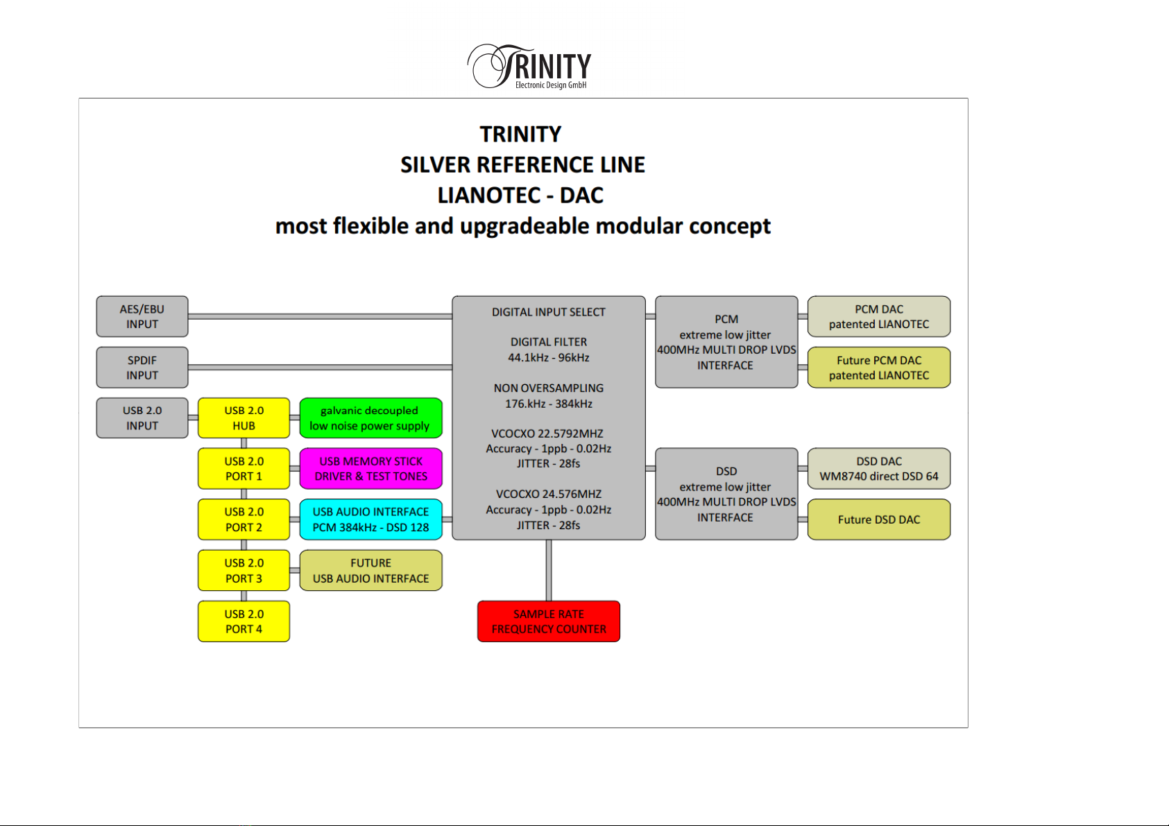
The DAC supports the playback of audio files with 44.1kHz – 384kHz sampling rates and 24bit resolution and DSD 64 in a
direct DSD mode, which means the DSD signal is not processed inside the DAC.
The asynchrony SB interface is galvanic de-coupled from the computer side and is synchronized with two full customized,
hermetic sealed Voltage Controlled Oven Controlled Xrystal Oscillators VCOCXO, which deliver the 2 master clocks of
44.1kHz*512=22.579200.0MHz and 48kHz*512=24.576000.0MHz.
The exact frequency can be fine-tuned to compensate any aging for the next 20years.
The selected master clock is available as a 50Ohm output signal on the back of the DAC.
The a ura y is 1ppb or 0.02Hz (factory setting) with a tuning range of +/-1000ppb.
The outstanding extreme low jitter is 28fs (10Hz-100kHz).
These VCOCXOs are very low sensitive to any a eleration with 1ppb/g, measured in the worst-case axis.

The sampling frequency (the frequency of the word clock) of all input signals is measured with the help of a real frequency
counter. The frequency counter works also for the XLR and SPDIF inputs and is based on an own reference TCXO with 2ppm
accuracy.
The TRINITY DAC has its own SB 2.0 Hub inside the DAC.
The Port 1 is used by a SB Memory Stick, which contains the driver, firmware and test tones to check the DAC. Customers
can even write own music files on it.
The Hub has its own galvanic decoupled low noise 5V power supply. Therefore, the PC side of the SB interface gets its
power supply from the DAC and not from the noise PC.
A further advantage of the SB Hub is that you can easily add additional SB Interfaces.
The DAC is designed as a very modular concept.
It has space for 4 DAC modules, which have all their own XLR connector.
The SB Interface has two separate signal paths. One is for the PCM and another independent path is for DSD.
That means you can run 4 different DAC architectures inside one DAC enclosure.
Enjoy pure sound reproduction with our product.
Sincerely Yours
TRINITY Team


CONTENTS
Safety Instructions ................................................................................................. 5
Scope of Supply .........................................................................................................................................6
Transportation and Cleaning .......................................................................................................................6
Selecting the Power Voltage .......................................................................................................................7
Connecting and Starting ..............................................................................................................................7
Wiring p.....................................................................................................................................................8
Technical descriptions ............................................................................................................................... .9
THE FINAL MEAS REMENTS.............................................................................................................. .20
Warranty...................................................................................................................................................... 27
Support.........................................................................................................................................................28

SAFETY INSTRUCTIONS
1. Please read this operating manual carefully and observe all the instructions affixed to the appliance or written in this
manual.
2. Install this product on a stable surface and make sure that nobody can trip over the cables.
3. This product should only be connected to a power source indicated on the product. If you are unsure what power source
you have in your region, please contact your local power utility.
4. Never operate this product near water or with wet hands. If the product comes in contact with liquids, immediately
disconnect it from the power source.
5. To exclude the risk of an electric shock, please never expose the product to the rain or other source of liquid.
6. In thunderstorms, do not install the product or put it into operation.
7. Never attempt to open the appliance or repair it yourself. If you open or remove the enclosure, you may expose parts that
are subjected to dangerous levels of voltage. Any unauthorized opening of the appliance will cause the warranty claim to
become null and void.
8. Do not allow children to play with electrical appliances without adult supervision. Children do not always recognize the
possible risks and consequences.

SCOPE OF SUPPLY
The scope of supply comprises:
•TRINITY DAC with internal SB 2.0 H B
•SB Stick with Windows drivers and Sample Rate Test Files inside of the DAC,
•Dimension 400mm x 300mm x 96mm plus 15mm feet, weight 32kg
•1 x Flight Case, weight: 35kg, dimension: 55cm, 46cm, 24cm
TRANSPORTATION AND CLEANING
Please only transport the parts listed in the scope of supply in the supplied flight case and use the supplied cotton gloves
when unpacking and installing the appliances to avoid scratching the enclosures.
Clean the surfaces using the supplied microfiber cloth: immerse the cloth in lukewarm water containing no detergents and
then carefully wipe the surface when the cloth is almost dry.
Never use hemi al or aggressive detergents.

SELECTING THE POWER VOLTAGE
The implemented wide-range switched mode power supply modules allow an operation from 100Vac to 240Vac. The two
fuses on the primary side are placed inside of the power entry module and filter.
CONNECTING AND STARTING
To install the DAC, select a stable, level surface directly next to the turn table so that the connecting cable to the tone arm is
as short as possible. Avoid placing the appliance in direct sunlight and never place the modules directly next to radiators or
fan heaters.
Protect all supplied parts from humidity and moisture.
Only wire up the components when the device is switched off.

WIRING UP AND USB DRIVER INSTALLATION
1. Disconnect the DAC from the power source. Never disconnect any wires unless the device is switched off.
2. Connect the DAC inputs to the audio sources.
3. Connect the DAC to the LINE PREAMP.
4. The MAC Operating Systems does not need a special SB driver.
5. The Windows Operation System needs an installation of a dedicated SB driver, which is on the SB stick.
6. Follow the instructions of the installation procedure.
7. Choose the right output device and parameters in your media player.
9.
Play the supplied Sample Rate Test files with different sampling rates and check the measured sample rate on the display
in the front of the DAC. If the setting of the media player is correct, the measured frequency should be identical with
sample rate indicate in the name of the test files.

LIANOTEC
Linear Analog Oversampling Te hnology
In an article entitled “A Mathematical Theory of Communication” published in 1948, Claude E. Shannon described his theory
on signal sampling. See also:
http://people.math.harvard.edu/~ctm/home/text/others/shannon/entropy/entropy.pdf
In simple terms, the Nyquist theorem presents the minimum sampling rate that is required to reconstruct the original signal
without aliasing errors. In other words, the Nyquist theorem may be regarded more or less as a summary of this paper. What
many will overlook is the fact that this paper makes no mention of signal amplitude or phase. The result of this is that many
articles have appeared in the hi-fi press presenting the sampling theory incorrectly. To avoid any similar misinterpretations
with our LIANOTEC
arrangement, we want to describe in closer detail what this innovative technology has to offer.
Digital/Analog onverter
The time-discrete output signal of a digital/analog converter is a staircase signal. Figure 1 shows a 20-kHz sine-wave signal in
the time and frequency domains measured directly at the output of the D/A converter. Besides the 20-kHz signal, the
frequency domain shows pairs of frequencies that are referred to as sidebands. Their frequency results from the sampling
rate and the signal. In this case, the sampling rate is 384 kHz and the signal is a 20-kHz sine-wave. The sidebands are situated
symmetrically in relation to multiples of the sampling frequency, i.e. the first two sidebands are at 364 kHz and 404 kHz (384
kHz ±20 kHz), the next pair is at 748 kHz and 808 (2x384 kHz ±20 kHz), etc.

Spice simulation
of a common
multi bit
DAC architecture
Time domain
Frequency domain
20-kHz sine wave sampled at 384 kHz, no analog LP filter 20-kHz sine wave sampled at 384 kHz, no analog LP filter
Figure 1
20-kHz sine wave sampled at 384 kHz plus 60 kHz analog LP filter 20-kHz sine wave sampled at 384 kHz plus 60 kHz analog LP filter
Figure 2
Time/µSecs 2 0µSec s/d iv
0 2 0 40 60 80 100
LIANOTEC / mV
-800
-600
-400
-200
0
200
400
600
800
Freque ncy /MHertz 200 kHertz/ div
0 0.2 0.4 0.6 0.8 1 1.2 1.4 1.6 1.8 2
Spectrum(LIANOTEC) / V
20p
40p
100p
200p
400p
1n
2n
4n
10n
20n
40n
100n
200n
400n
1µ
2µ
4µ
10µ
20µ
40µ
100µ
200µ
400µ
1m
2m
4m
10m
20m
40m
100m
200m
400m
1
Time/µSecs 2 0µSec s/d iv
40 60 80 10 0 120
LP_Filter / mV
-800
-600
-400
-200
0
200
400
600
800
Freque ncy /MHertz 200 kHertz/ div
0 0.2 0.4 0.6 0.8 1 1.2 1.4 1.6 1.8 2
Spectrum(LP_Filter) / V
10f
100f
1p
10p
100p
1n
10n
100n
1µ
10µ
100µ
1m
10m
100m
1

The Low-Pass Filter
Figure 3 shows the recommended low-pass-filter circuit and its frequency response. These frequency components must be
filtered out, of course. This is the task of the analog active low-pass filter, which is located downstream of every conventional
D/A converter.
Figure 2 shows the output signal of the D/A converter downstream of a 60-kHz low-pass filter. Even if the sine-wave signal
looks smooth, the FFT shows that the high-frequency components are attenuated from 50 mV to approx. 1 mV, but not
completely removed.
Spice simulation
Schematic
Frequency domain
60-kHz LP filter 60-kHz LP filter
Figure 3
1.2n
C2
780
R 11
X2
OPA627/BB
15
V6
15
V3
LP_Filter_1
1. 6k
R10
4.7n
C1
1. 6k
R12
AC 1 0
V1
Freque ncy / Her tz
20 50 100 200 500 1k 2k 5k 10k 20k 50k 100k 200k 500k 1M
Group delay @ LP_Filter_1 / µSecs
Y2
0.5
1
1.5
2
2.5
3
3.5
4
4.5
dbV @ LP_Filter_1 / dB
Y1
-60
-50
-40
-30
-20
-10
0

The frequency response shows the attenuation of -32 dB at 384kHz. The FFT showed that the spectral components of 50 mV
were attenuated to approx. 1 mV. The attenuation in dB results as follows: 20log(1 mV/50 mV) = -34dB. We discovered that
the proposed second-order 60-kHz low-pass filter failed to filter out all of the interfering frequencies. As a result, it is possible
to deploy a higher-order low-pass filter, or lower the cut-off frequency from 60 kHz to 20 kHz. Either measure would result in
greater suppression of image frequencies, but the two measures together would clearly contribute to an impairment in the
sound. In the first case, there would be more electronic circuitry in the signal path; in the second case, there would be a
slight drop in frequency response. Even group delay distortion, the curve depicted in green, would deteriorate in both cases.
What is astonishing is that all of these negligible changes are clearly audible.

LIANOTEC
This is where LIANOTEC
comes in. The abbreviation stands for Linear Analog Oversampling Technology.
This innovative circuit topology was developed and patented by GTE GmbH and is now used by the spin-off TRINITY
Electronic Design GmbH.
It is based on the fact that additional oversampling points are obtainable by multiplying the number of D/A converters and
finding the right way to control them. This new type of interpolation is called LIANOTEC, since these interpolation points are
situated linearly between the original sampling points and are implemented without any digital signal processing.
The whole thing in the TRINITY DAC behaves like a quadratic series. Therefore, it means that two D/A converters are needed
for 2-way analog oversampling, 4 for 4-way oversampling, 8 for 8-way oversampling, etc.
The use of several D/A converter circuits in a single product is nothing new in itself. Burr-Brown brought out a similar design
as demo board EVM1702 in 1997. This concept was also launched on the market in different products. In all these solutions,
all the D/A-converter inputs and outputs are interconnected. This is made possible since the D/A converters supply an output
current that is easy to accumulate. However, this type of parallel circuit produces only a slight reduction in errors, such as
nonlinearities, harmonic distortion, and noise. The high-frequency interfering components remain untouched and must even
be attenuated in a downstream low-pass filter.
The LIANOTEC
arrangement is totally different. Here, only the outputs are interconnected. The inputs are supplied with the
required data by an additional control circuit. The electronic circuitry in this case is arranged precisely on top of the actual
converter board. This minimizes the connections to the converter circuits to exactly the same length for all ICs.
Figure 1 shows that the sidebands, as described in the theory, are multiples of the sampling frequency.

2x LIANOTEC
Figure 4 shows the output signal of an innovative 2-times analog oversampling arrangement. This shows very clearly which
potential this unique circuit topology introduces.
Note that the two sidebands at 384 kHz are fully suppressed.
Not only the multiples, but all of the other odd multiples of 384 kHz (1*Fs=368 kHz, 3*Fs=1.152 MHz, 5*Fs=1.920 MHz,
7*Fs=2.688 MHz, etc.).
The remaining visible sidebands are located at all multiples of 768 kHz.
Spi e Simulation LIANOTEC
Time domain
Frequency domain
2x LIANOTEC
20
-
kHz sine wave sampled at 384 kHz, no analog filter
2x LIANOTEC
20
-
kHz sine wave sampled at 384 kHz, no analog filter
Figure 4
Time/µSecs 20µ Secs /div
0 2 0 40 60 80 100
LIANOTEC / V
-1.5
-1
-0.5
0
0.5
1
1.5
Freque ncy /MHertz 200kHertz /div
0 0.2 0. 4 0.6 0.8 1 1.2 1.4 1 .6 1.8 2
Spectrum(LIANOTEC) / V
1p
10p
100p
1n
10n
100n
1µ
10µ
100µ
1m
10m
100m
1
10

4x LIANOTEC
The result of a 4-way analog oversampling setup is depicted in Figure 5.
Here, the sidebands at 768 kHz are suppressed as well as at all the odd multiples of 768 kHz.
What remains are the sidebands at 1.536 MHz and their multiples.
Spi e Simulation LIANOTEC
Time domain
Frequency domain
4x LIANOTEC
20
-
kHz sine wave sampled at 384 kHz, no analog filter
4x LIANOTEC
20
-
kHz sine wave sampled at 384 kHz, no analog filter
Figure 5
Time/µSecs 20 µSec s/d iv
0 2 0 40 60 80 100
LIANOTEC / V
-3
-2
-1
0
1
2
3
Freque ncy /MHertz 200kHer tz/d iv
0 0.2 0. 4 0.6 0.8 1 1.2 1. 4 1.6 1.8 2
Spectrum(LIANOTEC) / V
100f
1p
10p
100p
1n
10n
100n
1µ
10µ
100µ
1m
10m
100m
1
10

8x LIANOTEC
Figure 6, shows an 8-times oversampling setup as realized in the TRINITY DAC, were the 1.536 MHz and their odd multiples
are also erased. What remains are the sidebands at 3.072 MHz and their multiples. In other words, with an 8-way analog
oversampling setup, the first sideband is located at 3.072 MHz and, therefore, is far outside of the bandwidth for
conventional power amplifiers.
Spi e Simulation of the final TRINITY DAC
Time domain
Frequency domain
8x LIANOTEC
TRINITY
DAC
20
-
kHz sine wave sampled at 384 kHz, no analog filter
8x LIANOTEC
TRINITY
-
DAC
20
-
kHz sine wave sampled at 384 kHz, no analog
filter
Figure 6
Time/µSecs 20 µSec s/d iv
0 2 0 40 60 80 100
LIANOTEC / V
-6
-4
-2
0
2
4
6
Freque ncy /MHertz 200kHer tz/d iv
0 0.2 0.4 0.6 0.8 1 1.2 1.4 1.6 1.8 2
Spectrum(LIANOTEC) / V
100f
1p
10p
100p
1n
10n
100n
1µ
10µ
100µ
1m
10m
100m
1
10

Compared with the usual circuitry comprising analog low-pass filters mentioned at the start, the LIANOTEC
topology
produces significantly better sideband suppression. This means that, although there is no analog active low-pass filter in the
signal path of the TRINITY
DAC, filtering is much enhanced by several orders of magnitude than conventional D/A converters.
IMPULSE RESPONSE
But this is far from being the only improvement that LIANOTEC
offers. It is well known that all digital oversampling techniques
can be characterized by their impulse responses. As such, there are solutions that are impulse-optimized and those that are
frequency response-optimized. The LIANOTEC
topology is both impulse-optimized and frequency response-optimized, since
it has an ideal impulse response and, therefore, represents the epitome of interpolation techniques. Figure 7 shows the
reproduction of a 10-kHz square-wave signal sampled at 192kHz. The LIANOTEC
arrangement depicts a perfect square.
Spi e Simulation of the final TRINITY DAC with 8x LIANOTEC and a re tangular pulse as input signal
8x LIANOTEC TRINITY-DAC
10-kHz square wave sampled at 192kHz, no analog filter
Figure 7
Time/µSecs 20 µSec s/d iv
0 20 40 60 80 100 120 140 160 180 200
LIANOTEC / V
-6
-4
-2
0
2
4
6

Impulse Resoponse
of the TRINITY DAC in Non Oversampling Mode
Summary
LIANOTEC
is a patented unique topology whi h improves all parameters of a multi-bit D/A onverter.
This manual suits for next models
1
Table of contents
Popular Media Converter manuals by other brands

B&B Electronics
B&B Electronics Industrial Media Converter EIR102 quick start guide

I-novative
I-novative Factory-Link-SPE-G user manual

Bang & Olufsen
Bang & Olufsen BEOLINK VIDEO user guide

Cavus
Cavus CAV-BXAU03 quick start guide

ProofVision
ProofVision PV26BT user manual

ADF Web
ADF Web HD67E14-A1 user manual