Triol AT27 ED Series User manual


Dear owner of Triol equipment!
We are very glad that you have purchased a Triol AT27 variable frequency drive. We
are sure that this equipment will bring profit to your enterprise, as well as provide
safe and reliable control of the technological process.
We strongly recommend that you carefully read the operational documentation
before carrying out any operations with the variable frequency drive.
List of operational documentation for AT27 line ED, DD, MV:
1. Installation manual
2. Operation manual
3. Programming manual
4. Registration certificate
Equipment specifications, as well as the warranty conditions of the variable
frequency drive are specified in the registration certificate.
We recommend that you always follow the instructions in the service book. After
all, only timely and properly serviced equipment will operate its service life and even
longer.
Best regards, Triol Corporation

List of Abbreviations
The following abbreviations and designations are used in the text of
the document:
VFD (VFD АТ27) - Variable frequency drive AT27 ED, DD, MV lines;
Power cell AT27;
Power cell compartment
transformer compartment
switching compartment
Control system compartment
UPS - Uninterruptible power supply
transformer cabinet
power cell cabinet
Spare parts
UMKA-27
Control system
IM - Installation manual
switchgear

Introduction .................................................................................................. 6
Purpose of the document...................................................................................................6
1. General safety instructions ...................................................................... 7
1.1 General warnings..........................................................................................................7
1.2 Safety Requirements ....................................................................................................8
2 Equipment description .............................................................................. 9
2.1 VFD AT27 ED line..........................................................................................................9
2.2 VFD AT27 DD, MV lines ..............................................................................................10
3. Transportation ................................................................................... 12
3.1 Requirements to transportation of VFD AT27 ED line..............................................12
3.2. Requirements for loading and unloading AT27 ED line ......................................14
3.2.1 Unloading requirements for road and rail transport.....................................................14
3.2.2 Unloading requirements for shipping container ...........................................................16
3.3 Requirements for transportation of VFD AT27 DD, MV lines .................................16
3.3.1 Unloading requirements for road and rail transport .....................................................18
3.3.2. Unloading requirements for shipping container ......................................................20
3.3.3 Unloading requirements for shipping container ...........................................................23
3.3.4 Loading VFD AT27 in a truck ...........................................................................................24
4. Storage conditions of VFD AT27.......................................................... 26
5. General requirements to the place of installation ............................ 27
6. Removing and reassembling the package........................................ 29
6.1 Removal of the package from the VFD AT27 ED line...............................................30
6.2 Removal of package from VFD AT27 DD, MV line....................................................31
7. Preservation and re-conservation ..................................................... 34
7.2 Re-conservation ..........................................................................................................34
8. Рackaging storage and disposal ....................................................... 36
8.1 Рackaging storage......................................................................................................36
8.2 Disposal of packaging................................................................................................36
9. Acceptance ........................................................................................ 37
10. Installation ......................................................................................... 39
10.1 Installation at the place of operation ......................................................................39
10.1.1 Slinging of the VFD AT27 ED line. ........................................................................39
10.1.2 Slinging of VFD AT27 DD, MV lines. .............................................................................41

10.2 Substrate Requirements ..........................................................................................41
10.3. Installation and mounting of fans......................................................................45
10.3.1. Installation and mounting of the VFD AT27 ED line ............................................... 45
10.3.2. Fans installation and mounting of VFD AT27 DD, MV lines .................................. 47
10.4. UPS installation and connection in AT27 ED line..................................................49
10.5 UPS installation and connection in AT27 DD, MV lines .........................................50
10.6. Mutual arrangement and mounting of the VFD AT27 cabinets .......................51
10.6.1. Cabinets arrangement of VFD AT27 ED line ........................................................... 51
10.6.2. Cabinets arrangement of VFD AT27 DD, MV lines ................................................. 51
11. Electrical mounting............................................................................ 53
11.1. General information about electrical mounting ....................................................53
11.2. Grounding the VFD АТ27 ........................................................................................54
11.3. Electromagnetic compatibility ...............................................................................55
11.4. Guidelines for selecting power cables..............................................................56
11.5. Power circuits mounting.....................................................................................56
11.5.1 Power circuits mounting of AT27 ED line ......................................................56
11.5.2. Power circuits mounting of AT27 DD, MV lines...................................................... 60
11.6 Control system cable selection ...............................................................................63
11.7. Wiring of auxiliary AC27 power supply ..............................................................63
11.8. Selection of control system cables ...................................................................63
11.9 Installation of control wiring ..............................................................................64
11.10. Wiring of communication interface circuits RS485.......................................65
12. Pre-operational check-up .................................................................. 67
13. Warranty and service ......................................................................... 68
13.1. Warranty obligations of the manufacturer ........................................................68
13.2. The customer loses the right to warranty service in the following cases: ......68
13.3. False call..............................................................................................................70
13.1 Service center has the right to refuse free warranty service of the equipment
in the following cases:......................................................................................................71
Appendix 1.................................................................................................. 72
Appendix 2. Mass dimensions................................................................... 73
Appendix 3.................................................................................................. 91

Introduction
Triol AT27 is a Variable Frequency Drive, based on a multilevel cascade inverter,
designed to control three-phase induction electric motors of 3-11 kV Voltage and
capacity of 160-8000 kW.
Before starting mounting of the VFD AT27 equipment, please read this IM carefully.
Violation of the rules of installation of the equipment can lead to damage of the
product, damage to the equipment connected to it, reduction of its performance
characteristics, service life in general, to the withdrawal of the warranty on the
equipment.
This IM should be kept with the VFD for the entire service life of the VFD.
Purpose of the document
The present document contains the information and requirements for
transportation, installation, mounting and assembly of Variable Frequency Drive AT27
ED, DD, MV lines.

1. General safety instructions
1.1 General warnings
This section contains safety instructions that must be followed when mounting the
VFD. Failure to follow the safety instructions may result in injury to persons and
damage to the VFD, the motor and the connected process equipment.
Read the safety instructions carefully before working on the VFD.
The following warnings, precautions, and notes are intended to ensure the safety of
the user and to prevent damage to the product.
Please read this information carefully, as this will ensure your personal safety and
the longevity of the VFD.
Disregarding the warnings in this manual may cause danger to life, serious bodily
injury, or serious property damage.
The illustrations and photos in this IM may be shown without covers and protective
guards to show the internal parts of the product. Ensure that all covers and protective
guards are in place before using or starting up the drive.
Any illustrations, photos or examples used in this IM are for the VFD AT27 ED, DD,
MV lines only and may not be used with other Triol Corporation products.
If this IM is lost or damaged, a new copy can be ordered from Triol Corporation
through the official website https://triolcorp.com or using the contacts given in the
Warranty and Service section.
General Safety Precautions
This IM includes two types of instructions that you should pay special attention to
when performing any operation on the Variable Frequency Drive:
Electrical hazard symbol. Failure to follow the warnings associated with
this symbol creates the risk of electric shock to Staff and/or damage to
the equipment.
Failure to follow the warnings under this symbol creates a hazardous
condition that is not related to electrical hazards and can cause serious
injury or danger to life and/or damage to the equipment.
WARNING! This IM is intended for personnel involved in unloading,
loading, installing and assembling the VFD. Please read this manual
before starting any operation described above. In developing this IM, we
have assumed that the user is familiar with the handling and installation instructions,
basic electrical engineering, electrical components, and wiring diagrams.

WARNING! The VFD is connected to hazardous voltages and operates
machinery with rotating mechanical parts, which could be a source of
danger. For this reason, ONLY qualified Staff is allowed to carry out the
electrical mounting of the VFD Triol AT27
1.2 Safety Requirements
Before you start unloading and installing VFD AT27, please read these safety
requirements, IM and work project.
Loading and unloading operations and transportation of cargo must be carried out
in accordance with the requirements of local standards, taking into account general
safety requirements, labor safety regulations for loading and unloading and placement
of cargo.
Loading, unloading and placing of VFD with or without the use of lifting equipment,
as well as its installation, described in this IM, must be performed by qualified staff.
The area where the equipment is unloaded from the vehicle must be cordoned off.
Warning signs shall be posted in areas where people walk by the equipment.
When loading, unloading and moving the cargo, it is not allowed to use defective
lifting machines, hooks, removable lifting devices, carts, other devices and tools.
2 Equipment description
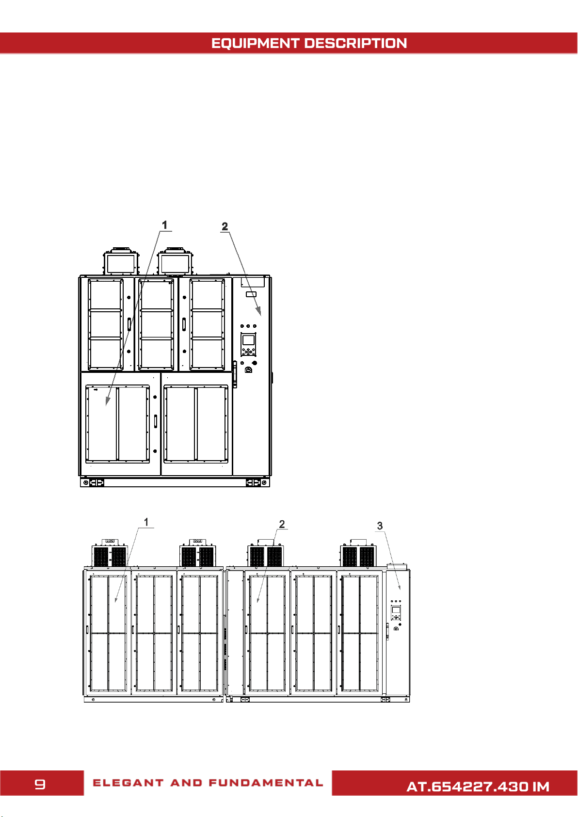
2.1 VFD AT27 ED line
The configuration of VFD AT27 ED line cabinets depends on the mains supply
voltage and the number of power cells in a phase.
By design, VFD AT27 ED line are available in two basic configurations:
- Single cabinet ("mono cabinet")
1. Transformer and Power cell cabinet
2. Control system compartment
- Double cabinet
1. Transformer
cabinet
2. Power cell
cabinet
3. Control
system compartment

2.2 VFD AT27 DD, MV lines
VFD AT27 DD, MV lines are available in a single cabinet configuration and are
divided into compartments according to their functional purpose.
The design of the VFD AT27 DD line:
1
2 3 45
1. Cooling system fan(s);
2. Filtration and air treatment compartment;
3. Transformer and power cell compartment;
4. Control system compartment;
5. Switching compartment.
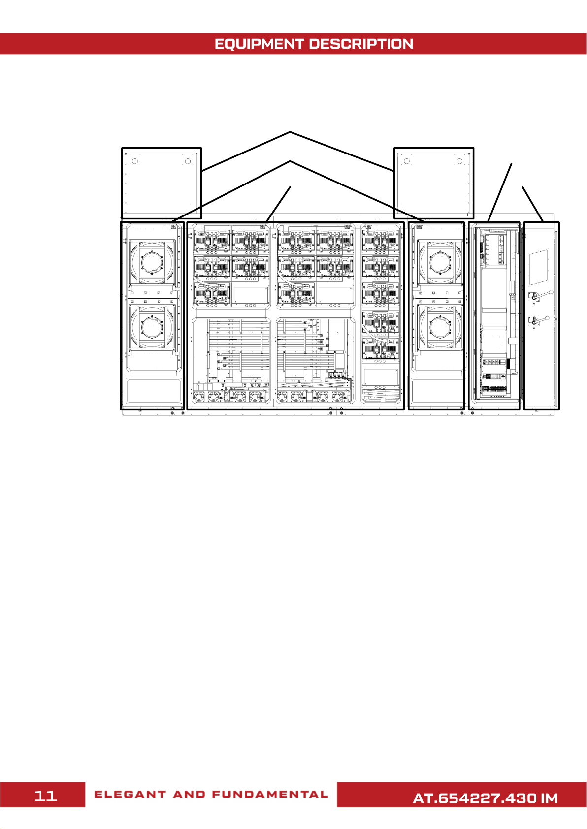
The design of the VFD АТ27 MV line:
1
2
3
4
5
1. Outside contour cooling fan;
2. Heat exchange compartment (heat exchangers and fans of the inside cooling contour);
3. Transformer and power cell compartment;
4. Control system compartment;
5. Switching compartment.
3. Transportation
3.1 Requirements to transportation of VFD AT27 ED line
The VFD package is intended to protect the product from external influences during
transportation by water, land and air transport. Necessary protective measures should
be taken against water, oils, other chemically active liquids and dirt getting on the
package. During transportation and moving the VFD by any kind of transport, it is
necessary to avoid possible damages caused by external mechanical impacts and
careless handling.
Transport stickers applied on the package reflect the requirements for
transportation, loading, unloading and storage conditions of the product. These
requirements should be followed during transport operations.
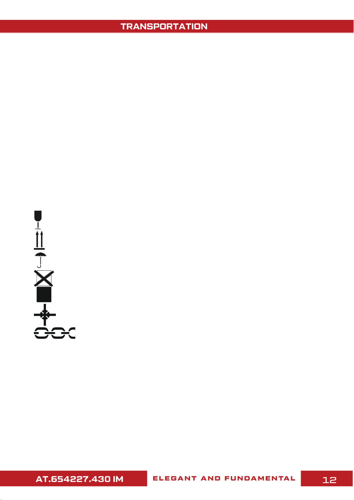
The packaging bears the following handling marks (warning notices):
Fragile. Take care
Top
Protect from moisture
Cargo not stackable
Center of gravity
Sling here
The packaging bears the following information inscriptions:
- Gross and net weight of the package;
- Dimensions of the package.
Information about package items, their quantity and mass and dimensions
parameters are indicated in the packing list located on the front side of the package.

Transportation conditions included in the VFD set must comply with the following
requirements in terms of mechanical factors:
- Transportation by automotive transport with a number of transloadings not exceeding
four. Transportation by cobblestone and unpaved roads should be carried out at a
speed of up to 40 km/h.
- Transportation by different vehicles: by air or by rail, together with automotive
transport, with a total number of transloadings not exceeding four;
- Transportation, including transportation by sea.
Loading and unloading operations using cranes and lifting machines shall be
performed by the workers who have passed special training and knowledge test on
labor protection issues and are authorized to perform such works. When performing
unloading operations, the general rules for slinging work must be followed.
WARNING! Placement and fastening of the VFD package items in the
vehicle must ensure their stable position, exclude the possibility of their
displacement and hitting each other, as well as the walls of the vehicle.
In case of the VFD AT27 ED line, the
package item is secured to the trailer
or railway platform with slings. For
this purpose, special eyelets are
provided in the package item.
Securing the VFD AT27 ED line on the railway platform

Before placing the cargo on the railway platform, remove the tarpaulin cover from
the packaging and stow it in the packaging pocket provided for this purpose. After
unfastening the cargo on the railway platform, place the tarpaulin cover on the
packaging.
3.2. Requirements for loading and unloading
AT27 ED line
WARNING! After unloading, it is necessary to check the complete set of the
VFD according to the registration certificate and the number of package
items!
Overall dimensions, net and gross weight are shown on the package of each
package item. The VFD is unloaded in the original package with a crane of the required
lifting capacity.
3.2.1 Unloading requirements for road and rail transport
Unloading of the VFD AT27 ED line cabinets from the car or railway platform is
carried out by encircling the cabinet from below with textile slings with load-carrying
capacity not less than gross weight of the lifted cargo, as shown in the figure below.


3.2.2 Unloading requirements for shipping container
To unload equipment from a shipping container such as an Open Top, open the top
of the container, attach soft slings to the shipping areas, and use a crane to remove
the packaged equipment from the container, as shown below.
3.3 Requirements for transportation of VFD
AT27 DD, MV lines
The VFD package is intended to protect the product from external influences during
transportation by water, land and air transport. Necessary protective measures should
be taken against water, oils, other chemically active liquids and dirt getting on the
package. During transportation and moving the VFD by any kind of transport, it is
necessary to avoid possible damages caused by external mechanical impacts and
careless handling.
Transport stickers applied on the package reflect the requirements for
transportation, loading, unloading and storage conditions of the product. These
requirements should be followed during transport operations.

The packaging bears the following handling marks (warning notices):
Fragile. Take care
Top
Protect from moisture
Cargo not stackable
Center of gravity
Sling here
The packaging bears the following information inscriptions:
- Gross and net weight of the package;
- Dimensions of the package.
Information about package items, their quantity and mass and dimensions
parameters are indicated in the packing list located on the front side of the package.
Transportation conditions included in the VFD set must comply with the following
requirements in terms of mechanical factors:
- Transportation by automotive transport with a number of transloadings not
exceeding four. Transportation by cobblestone and unpaved roads should be carried
out at a speed of up to 40 km/h.
- Transportation by different vehicles: by air or by rail, together with automotive
transport, with a total number of transloadings not exceeding four;
- Transportation, including transportation by sea.
Loading and unloading operations using cranes and lifting machines shall be
performed by the workers who have passed special training and knowledge test on
labor protection issues and are authorized to perform such works. When performing
unloading operations, the general rules for slinging work must be followed.
WARNING! Placement and fastening of the VFD package items in the
vehicle must ensure their stable position, exclude the possibility of their
displacement and hitting each other, as well as the walls of the vehicle.
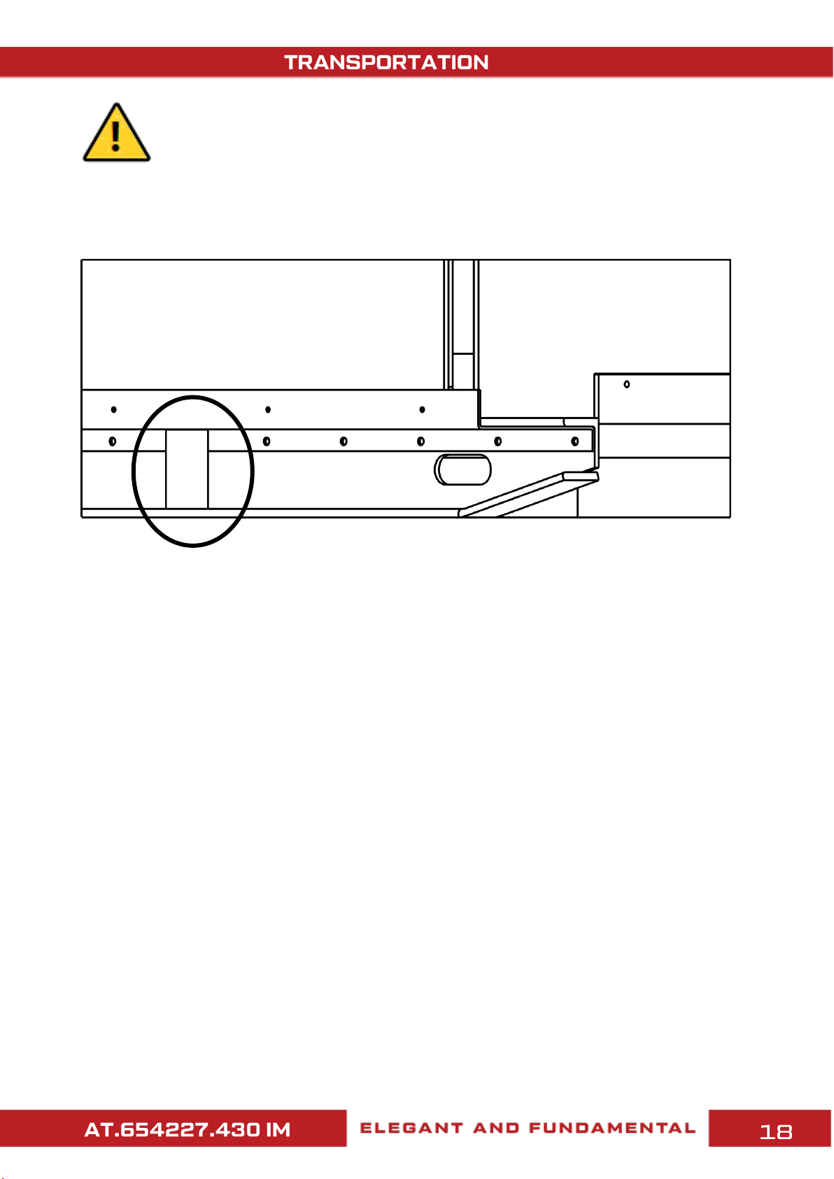
In case of the VFD AT27 DD, MV lines, the package item is secured on the platform of the
vehicle with the force elements in the packaging frame. When securing packages with ropes
or chains in the vehicle, the protection and integrity of the package must be ensured.
3.3.1 Unloading requirements for road and rail transport
Slinging of the VFD AT27 DD, MV lines is performed by 4 lugs located in the upper part of
the item.
Before placing cargo on the railway platform, remove the tarpaulin cover from the
packaging and place it in the pocket provided for this purpose. After unfastening the load on
the railway platform, place the tarpaulin cover on the package.

Location of the lifting eyelets for the VFD AT27 DD, MV lines
WARNING! When slinging the VFD AT27 DD, MV lines, be sure to use all 4
strapping attachments located at the top of the VFD cabinet.
WARNING! Do not lift, move or lower the equipment unless there are people at
a safe distance from it.
To load/unload the VFD AT27 DD, MV lines, use rigging
brackets mounted on the item's eyelets. The load capacity
of the rigging bracket must be at least 4 tons and the
diameter of the fixing rod must not exceed 34 mm (1.33″).
Example of a rigging bracket
When loading/unloading, the angle between sling branches should not exceed 90°.
This manual suits for next models
2
Table of contents
Popular Industrial Equipment manuals by other brands


BVA Hydraulics
BVA Hydraulics HP0205 instruction manual

Cost Effective Equipment
Cost Effective Equipment Apogee Developer owner's manual

Megger
Megger Baker EP1000 installation guide

Tektronix
Tektronix 7B92 instruction manual

Stahl
Stahl isPAC HART 9196 Series operating instructions

Wadkin
Wadkin PBR-HD instruction manual


