Cost Effective Equipment Apogee Developer User manual

Owner’s Manual
Apogee™ Developer
www.costeffectiveequipment.com
+1-573-466-4300

Cee® Apogee™ Developer Manual
Page 2of 15
Contents
1. Apogee™ Developer Introduction...........................................................................................................4
1.1. Confidentiality Statement ................................................................................................................................ 4
1.2. Warranty............................................................................................................................................................... 4
1.3. Returned Materials............................................................................................................................................. 4
1.4. Model and Revisions......................................................................................................................................... 5
1.5. Safety Hazards/Precautions............................................................................................................................ 5
1.6. Overview of Equipment-Specific Hazards................................................................................................... 5
1.7. Electrical............................................................................................................................................................... 5
1.8. Mechanical........................................................................................................................................................... 5
1.9. Chemical............................................................................................................................................................... 6
1.10. Lockout/Tagout Procedures and Information ........................................................................................ 6
1.11. Intended Use of Machine.............................................................................................................................. 6
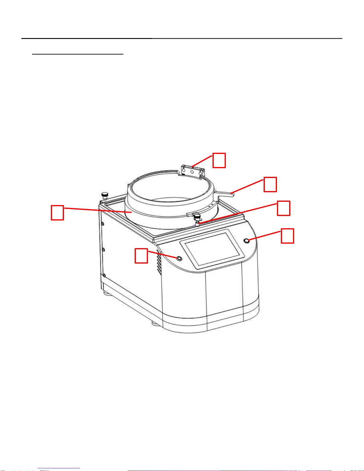
2. Equipment Description ............................................................................................................................7
2.1. Dimensions.......................................................................................................................................................... 8
2.2. Programmability................................................................................................................................................. 8
2.3. Precision............................................................................................................................................................... 8
2.4. Reliability.............................................................................................................................................................. 8
2.5. Bowl Design......................................................................................................................................................... 8
2.6. Utilities.................................................................................................................................................................. 9
3. Installation ................................................................................................................................................9
3.1. Floor Space Requirements.............................................................................................................................. 9
3.2. Facilities Requirements.................................................................................................................................. 10
3.3. Environment...................................................................................................................................................... 11
3.4. Unpacking/Inspection..................................................................................................................................... 11
3.5. System Installation and Setup...................................................................................................................... 11
3.6. Start Up............................................................................................................................................................... 12
4. Developer Use and Operation................................................................................................................13
4.1. Spin Chuck......................................................................................................................................................... 13
4.2. 5- Hole Dispense Nozzle Hub........................................................................................................................ 13
4.3. Lid Adjustment.................................................................................................................................................. 13
5. Preventative Maintenance......................................................................................................................14
5.1. Safety Checks................................................................................................................................................... 14
5.2. Mechanical Checklist...................................................................................................................................... 14
5.3. Utility Checks.................................................................................................................................................... 14

Cee® Apogee™ Developer Manual
Page 3of 15
5.4. Cleaning.............................................................................................................................................................. 15

Cee® Apogee™ Developer Manual
Page 4of 15
1. Apogee™ Developer Introduction
1.1.Confidentiality Statement
Information supplied is for the use in the operation and/or maintenance of Cee equipment.
Neither this document nor the information it contains shall be disclosed to others for manufacturing or any
other purpose without written authorization from, Cost Effective Equipment, LLC.
1.2.Warranty
Cost Effective Equipment, LLC warrants to the original purchaser (Buyer) that equipment is free from
defects in material and workmanship under normal use and service in accordance with Cee instructions
and specifications. Buyer Shall promptly notify Cee of any claim against this warranty, and any item to be
returned to Cee shall be sent with transportation charges prepaid by Buyer, clearly marked with a Return
Authorization (RMA) number obtained from Cee Customer Support. Cee’s obligation under this warranty is
limited to the repair or replacement, at Cee option, of any equipment, component or part which is
determined by Cee to be defective in material or workmanship. This obligation shall expire one (1) year
after the initial shipment of the equipment from Cee.
This warranty shall be void if:
(a) Any failure is due to the misuse, neglect, improper installation of, or accident to the equipment.
(b) Any major repairs or alterations are made to equipment by anyone other than a duly authorized
representative of Cee. Representatives of Buyer will be authorized to make repairs to the equipment
without voiding warranty, on completion of the Cee training program.
(c) Replacement parts are used other than those made or recommended by Cee.
CEE MAKES NO OTHER WARRANTIES, EXPRESSED OR IMPLIED, WITH RESPECT TO EQUIPMENT.
NO WARRANTY IS MADE AS TO THE MERCHANTABILITY OF THE EQUIPMENT NOR ITS FITNESS
FOR ANY PARTICULAR PURPOSE. In no event shall Cee be liable for consequential loss or damages,
however caused. No person or representative of Cee is authorized to assume for Cee any liability in
connection with Equipment nor to make any change to this warranty unless such change or modification is
put in writing and approved by an authorized representative of Cee in writing.
This warranty shall be governed by the laws of the state of Missouri U.S.A.
1.3.Returned Materials
Any materials, parts, or equipment returned Cost Effective Equipment, LLC must be clearly labeled with a
Return Material Authorization (RMA) number.
To obtain a RMA number, contact:
Cee Customer Support
Telephone: (573) 466-4300
E-Mail: support@costeffectiveequipment.com
Web Address: http://www.costeffectiveequipment.com
Shipping information with RMA number:
Attn: Cee Customer Support
Cost Effective Equipment
3703 HyPoint Blvd
Rolla, Missouri 65401

Cee® Apogee™ Developer Manual
Page 5of 15
1.4.Model and Revisions
The model and serial number information for the Cee® Apogee™are located on the rear panel
near the power inlet. Software version information can be found on the About screen. See
DataStream™ Manual for screen shots and a detailed explanation of the system software.
1.5.Safety Hazards/Precautions
Read this manual in its entirety before operating the machine.
1.6.Overview of Equipment-Specific Hazards
The unit is very heavy and proper precautions should be taken when handling the machine to
minimize risk of injury. Labels are placed on the machine to identify areas where caution is
needed during operation.
1.7.Electrical
High voltage is present in the machine. Disconnect the power before servicing.
Stored electrical energy is present in the machine. Before servicing allow sufficient time for
discharge. The servo amp has a charge light; do not service the machine until this light has gone
out.
1.8.Mechanical
This machine uses compressed gasses, which can provide motive force for components and
can expand violently upon decompression. Disconnect N2 or CDA before removing any panels.
The machine is capable of very high-speed rotation. Ensure all lids and panels are in place
before rotating these devices.
Ensure that all panels are on and in their correct locations before powering up or operating.
When opening the lid be aware of the pinch point at the hinge cover. Open the lid only by
using the handle on the lid.
The unit is very heavy and proper precautions should be taken when handling or moving the
machine to minimize risk of injury.

Cee® Apogee™ Developer Manual
Page 6of 15
1.9.Chemical
Ensure chemical compatibility of all chemicals and materials being used inside the machine.
This includes all wetted parts of the storage, supply, dispense, and waste systems.
Ensure chemical compatibility of all chemicals with each other. All dispensed materials are
held in one common waste storage tank. Check for reactions between chemicals before use.
Flammable Chemicals. No open flames/sparks.
Relieve pressure before opening canisters, tanks, cartridges, or syringes to refill.
Relieve pressure and shut off chemical valves before servicing supply lines, dispense valves
or other components.
Relieve pressure and shut off chemical valves before removing spin lid or changing BSR
tubes, EBR tubes, or any other dispense nozzle or spray tip.
Flush tubing and valves with an appropriate solvent and drain system before servicing.
When draining waste tank, use appropriate containers and connection methods.
Ensure proper ventilation/exhaust is used at all times.
Always wear the proper Personal Protective Equipment for the job. This includes safety
glasses, gloves and other equipment as needed to protect from mechanical and chemical
hazards.
1.10. Lockout/Tagout Procedures and Information
Before servicing, turn off the machine and remove the power inlet cord by disconnecting the plug
where it enters the machine.
1.11. Intended Use of Machine
The Cee® Apogee™Developer is intended for use as a Semiconductor/Optical application spin
coating machine. It is primarily intended for substrates up to the maximum size.
The Cee® Apogee™Developer is not intended for use in food or medical applications or for use
in hazardous locations.
The Cee® Apogee™Developer is intended for use only by properly trained personnel wearing the
proper personal protective equipment. Anyone not trained in the proper use of the Apogee™
Developer and have not fully read this manual should not operate the equipment.
The Cee® Apogee™Developer is intended for use in a cleanroom environment to provide the
proper processing conditions for the substrates. If it is used outside of a cleanroom environment,
the substrate cleanliness may be compromised.
The Cee® Apogee™Developer is not intended for use in a hazardous or explosive environment.

Cee® Apogee™ Developer Manual
Page 7of 15
2. Equipment Description
The Cee® Apogee™ Developer delivers track-quality performance, with revolutionary interface
capabilities and the utmost in chemical compatibility, in an efficient, space-saving design.
Fully programmable and user-friendly, the Cee® Apogee™ Developer features the accuracy and
repeatability needed to eliminate processing variability from critical experiments. With its convenient
compact footprint, wide array of chemical compatibility, and durability, this easy-to-use benchtop
system will provide years of high-performance operation, making the Cee® Apogee™ Developer
purchase a smart and cost-effective decision.
1. Power Button –Used to turn on and off the tool
2. User Presence Button –Used for remote access (see DataStream™ Manual)
3. Lid Sensor –Detects when the lid is closed
4. Developer Lid –Cover for the spin bowl (optional chimney hood available)
5. Lid Handle –Used to open and close the lid
6. Dispense Bracket –Used to hold dispense nozzles
1
2
3
5
4
6

Cee® Apogee™ Developer Manual
Page 8of 15
2.1.Dimensions
•13.25” (33.65 cm) W × 19” (48.26 cm) D × 12” (30.48 cm) H
•Machine weight: 40 lb (18.14 kg)
•Shipping weight: 100 lb (45.36 kg)
2.2.Programmability
•Touch screen interface and display
•Full-color alphanumeric-capable graphical user interface (GUI)
•A virtually unlimited number of user-defined recipe program steps
•0.1-second resolution for step times (9,999.9 seconds maximum step time)
•Spin speed: 0 to 6,000 rpm (12,000 rpm option at no charge)
•Spin speed acceleration: 0 to 30,000 rpm/s unloaded 0 to 23,000 rpm/s with a 200-mm
substrate 0 to 3,000 rpm/s with a 6” × 6” × 0.250” photomask in a recessed chuck
•Connectivity: USB/Ethernet port for communications for uploading/downloading process
parameters with DataStream™ technology
•Simultaneous dual automated dispense capability
•In-process/dynamic speed/acceleration control
2.3.Precision
•Spin speed repeatability: < 0.2 rpm
•Spin speed resolution: < 0.2 rpm
•Substrate sizes: < 1 cm to 200 mm round; 7” x 7” square
2.4.Reliability
•Indirect drive system protects the spin motor from contact with process chemicals and solvents
•Vacuum and lid interlock
•Industry-leading reliability and uptime
•1-year full warranty on parts and labor
•Free remote technical support (phone, email, fax) for the life of the product
•Application process assistance for life of the product
2.5.Bowl Design
•High-density polyethylene (HDPE) spin bowl for material compatibility
•Optional stainless or Teflon® bowl
•Optional polyethylene disposable liners available
•Versatile lid design allows process flexibility and repeatability
•Optional nitrogen purge for an inert spin environment
•Integrated drain and exhaust ports

Cee® Apogee™ Developer Manual
Page 9of 15
2.6.Utilities
•Voltage ranges: 100-125, 208-240 VAC, 50/60 Hz
•Power requirements: 655 watts
•Drain port: ¾” OD
•Exhaust port: 1” OD
•Vacuum: 20 to 25” Hg
•Exhaust: 20 to 50 cfm at 0.2” water
•Nitrogen or CDA (for automated dispense): 70 psi
3. Installation
3.1.Floor Space Requirements
The Apogee™ Developer is a bench top unit and requires a table or bench top for location. In
most cases the supporting structure will be larger than the unit itself. The recommended
freestanding space requirements are: 1'0" back to front and 0’3" side to side.
Dimensions: 13.25”L x 19”D x 12”H
Weight: 120 lbs

Cee® Apogee™ Developer Manual
Page 10 of 15
3.2.Facilities Requirements
The Apogee™ Developer requires the following utilities for operation. Locations for connections
are shown in the figure below.
1. USB Port –Used to update the software or download log files (see DataStream™ Manual)
2. Programmable Exhaust (Optional) –Communication port for optional Programable Exhaust module
3. Light Tree (Optional) –Port for optional light tree
4. Backside Rinse (BSR) (Optional) –Fitting for dispense material for optional Backside Rinse
5. Spin Bowl Exhaust Port –Exhaust port for spin bowl vapors. Port is 1 Inch OD and 50 CFM of
exhaust is recommended
6. Fuses –System protection fuses
7. System Vacuum –System vacuum for vacuum chuck. Recommended vacuum Supply is 20 in Hg at
a flow of 5 l/min. Port is ¼” barb fitting
8. Dispense Trigger –This port us used to connect to the optional dispense control box. This is used
when using automated dispenses
9. Accessory Port –This is used to talked to external I/O device to support extra outputs and inputs.
10. Ethernet –The ethernet can be used for remote recipe writing and remote control (see
DataStream™ Manual)
11. Spin Bowl Drain –The port that removes the liquid waste from the machine. The port is ¾” OD.
12. AC Power In –Cord is Provided. Single Phase 100-120V AC at 10 Amps (208-240V A/C option
available, see back label shown in Figure 1 to verify)
1
2
3
4
6
7
8
9
10
11
12
5

Cee® Apogee™ Developer Manual
Page 11 of 15
3.3.Environment
The Apogee™ Developer should be operated in a clean, low humidity environment.
3.4.Unpacking/Inspection
Thoroughly check machine for shipping damage. If physical damage is seen, DO NOT APPLY
POWER! Contact Cee™immediately.
The following items should be included with the shipment.
(1) Apogee™ Spin Developer
(1) Temperature and Humidity Sensor
(1) Power Cord with female power connector
(1) User & Installation Manual –CD or USB
Optionally included items:
Spin Chucks with Screws
Dispense Controllers
Dispense Valves
Dispense Nozzles
Dispense Hubs
3.5.System Installation and Setup
1. Lift the unit out of the packing crate by grasping the bottom only. Do not lift the by any of
the top covers or protrusions. Do not roll or turn the unit on its side or ends.
2. Remove plastic wrap and packing foam.
3. Place Cee™ Apogee™ Developer on a table of proper height and strength so that the
controls and spin chuck are at the proper ergonomic height.
4. Level the machine using the feet so that the spin chuck is level front-to-back and side-to-
side.
5. Thoroughly clean the spin bowl and spin chuck.
6. Connect utilities to the reference diagram in Section 3.7.2
(1) Connect the temperature/humidity sensor to the CAN terminal (#9).
(2) Connect the vacuum supply to the vacuum fitting (#7)
(3) Connect the drain to the drain port (#11)
(4) Connect the exhaust lines to the exhaust port (#5)
(5) Connect the optional dispense box is equipped to the dispense triggers (#8)
7. Connect any dispense as indicated on the separate dispense diagrams.
8. Plug in the machine.
9. Once plugged in, only the cooling fan should be powered, not the display.

Cee® Apogee™ Developer Manual
Page 12 of 15
3.6.Start Up
*For detailed software information, please refer to the DataStream™ manual
1. Install the tool as shown earlier in Section 4.
2. Press the lighted power switch to turn the tool power on.
3. The display should momentarily show boot screen and then show main screen.
4. Enter the username and password.
(1) The default username and password are “admin” and “admin2” respectively.
5. The tool will login and display the Process page.
6. Navigate to Tools- Manual Control to run system checks to ensure the tool is working properly.
(1) Turn vacuum on. Use your gloved hand to ensure vacuum is coming through the hole
of the shaft.
(2) Turn vacuum and off and check that the vacuum is turned off at the hole of the shaft.
(3) Close the lid and set the spin speed to 1000 rpm. Make sure that the shaft spins and
that the tool is reading 1000 rpm.
(4) Raise the lid to check the lid interlock. The tool should stop spinning.
(5) Ensure that the temperature/humidity sensor is reading on the parameter list.
(6) If equipped with optional dispenses, ensure that dispenses are triggering.
(7) If equipped with an optional programmable exhaust, ensure it is working properly.
7. Check that the spin chuck(s) with the tool work properly.
(1) The spin chucks have a slot that mates with the pin of the spin shaft.
(2) Position the spin chuck so the slot and the pin line up and press onto the shaft by
hand.
(3) Ensure that the pin fully engages the slot.
(4) If equipped with a screw, insert screw and tighten.
(5) Test vacuum of the spin chuck with a substrate using manual control. Set the vacuum
threshold to 64 kPa. If vacuum is less than 64 kPa, the chuck passes inspection.
(6) Turn vacuum off and remove the substrate.
(7) Removal of spin chuck is reverse of installation.
8. If the tool passes these checks, the tool is ready to operate. Begin by creating a recipe.

Cee® Apogee™ Developer Manual
Page 13 of 15
4. Developer Use and Operation
4.1.Spin Chuck
1. Locate Spin Chuck Flat head Cap Screw (Located in the center of Vacuum chuck).
2. Use a 3/32" hex key wrench and remove the spin chuck screw from the spindle.
3. Grasp the spin chuck and pull up and remove vertically.
4. Place new spin chucks in the same orientation as old and ensure that the spindle key
aligns with chuck slot.
5. Use a 3/32” hex key wrench to secure spin chuck screw in the center of new chuck.
4.2.5- Hole Dispense Nozzle Hub
All Cee® Developer utilize a standard multi-nozzle dispense center hub. This design allows up to
five (center-positioned) dispense nozzles to be mounted into the lid simultaneously and triggered
independently in any sequence or combination. The auto-dispense nozzles are all angled to the
center of the wafer and utilize precision suck-back control. Additionally, each nozzle features a
female luer adapter that houses a disposable tip to be placed at the point of use. This tip can
easily be changed to clear any dried material residue and/or manipulate the volume of the
dispense flow.
4.3.Lid Adjustment
The Apogee™ Developer is furnished with an adjustable lid. This lid allows the operator to regulate
the exhaust flow through the bowl region. Adjustments to the lid height can be a variable in
optimizing coating results.
To adjust the lid height, use the 3 thumb screws seen from the top of the lid (2 on the rear, and
one in the front). Before adjusting, the two bolts on the back of the equipment that mounts the lid
assembly to the back plate of the tool must be loosened. The lid is raised by rotating the
adjustment knobs counterclockwise and lowered by rotating them clockwise. For best results it is
recommended that each knob be adjusted in sequence and not more than one turn per sequence.
Once the desire adjustment has been made, tighten back the 2 lid assembly bolts on the back of
the equipment.

Cee® Apogee™ Developer Manual
Page 14 of 15
5. Preventative Maintenance
This maintenance manual provides personnel with procedure and guidelines for maintaining a Cee®
Apogee™ Developer. Below is a chart of recommend maintenance scheduling.
Maintenance Section
Maintenance Schedule
Safety Checks
Before daily tool use
Cleaning
After daily tool use
Mechanical Checklist
See Section 5.2 for Details
Utility Checks
See Section 5.3 For Details
5.1.Safety Checks
Inspect developer lid for the following defects:
(a) Loose assemblies
(b) Improper closure
(c) Improper bowl ring placement
5.2. Mechanical Checklist
1. Spin chuck cleanliness: If any material has built up on the spin chuck, it can be wiped clean
with most organic solvents isopropyl alcohol, or acetone. For major buildup of material, a
glass slide can be used to gently scrap the material away. Follow by wiping clean. A dirty spin
chuck could cause vacuum errors. See section 2.1 on detailed cleaning instructions. Daily
2. Spin chuck flatness: This can be seen visually with a straight edge. Small uniformity issues
such as a burr can be gently removed with a razor blade or a glass slide. Larger deformations
such as a damaged area from dropping can be removed with fine sandpaper. A non-uniform
spin chuck can cause vacuum errors. Quarterly
3. Bearing wear: Rotate the spindle shaft by hand. The shaft should easily spin with little noise.
If not bearing should be replaced. If grinding noise is heard during a process, bearing should
be replaced. Bad bearings can cause erratic spin speed and acceleration. Quarterly
4. Vacuum liquid trap: There should be no material in the vacuum trap. Material in the vacuum
trap will cause vacuum issues. Quarterly
5. Axial spindle shaft play: There should be no axial play in the shaft. Axial play will cause
excess bearing wear and possible vacuum error. Bi-annually
5.3.Utility Checks
1. Check all pressures for ranges specified in tool manual. Daily
2. Verify that there is a proper drain facility. Daily
3. Verify that the exhaust is functioning. Daily
4. Inspect all connections for proper installation. Bi-Annually
5. Verify that the AC power is of the proper voltage,and is connected. Bi-Annually

Cee® Apogee™ Developer Manual
Page 15 of 15
5.4.Cleaning
For cleaning, it is good practice to use the mildest solvent possible. The machine cabinet may be
cleaned using most organic solvents, acetone, isopropyl alcohol, or N-methylpyrrolidinone
(NMP). Caustic acids or bases should not be used. The spin bowl lid may be cleaned with
isopropyl alcohol, acetone, or water based cleaners.
Keep solvent from getting into the vacuum system. When cleaning the spin bowl, a small
substrate should be on the spin chuck to keep solvent from getting into the vacuum system. Spin
the wafer at approximately 200 RPM, and use solvent in a wash bottle to flush out the spin bowl.
Keep solvent from going down the spin shaft or the spin shaft tube. Shields and seals will protect
the bearings from a small amount of solvent, but they will not be able to handle large doses. Do
not direct the solvent stream down the shaft or tube.
Avoid getting solvent of any kind on the small yellow "Hot Surface" labels. Use only water-based
cleaner on the labels on the rear of the machine. Use only isopropyl or water based cleaner on
the "power on-off", Cee® logo, the yellow "Caution ... Eye Protection", and the "Cee®
model/serial number" labels. The display may be cleaned with glass cleaner, water, or isopropyl
alcohol.
This manual suits for next models
1
Table of contents
Popular Industrial Equipment manuals by other brands

Pfeiffer Vacuum
Pfeiffer Vacuum MPT 200 operating instructions

ESAB
ESAB A6 TPC 75 instruction manual

Siemens
Siemens SIRIUS 3RT2935 Original operating instructions

ermengineering
ermengineering LRBW-150 Use and maintenance manual

MICRO-EPSILON
MICRO-EPSILON ELTROTEC Endolight FOT LED instruction manual

ABB
ABB HT610640 Operation manual

DNS
DNS AS-410M Operation manual

Chentronics
Chentronics SureSpark LO-2 Installation and operation manual

Stahl
Stahl 9175 Series operating instructions

IEF Werner
IEF Werner euroLINE 120 operating instructions

Howmet Aerospace
Howmet Aerospace HuckForce HK32-002 instruction manual

Siemens
Siemens MICROMASTER 440 Getting started guide