SPX Waukesha Cherry-Burrell User manual

Waukesha ISR
INTEGRAL SPEED REDUCER SERIES
FORM NO.: 95-03010 REVISION: 08/1997 READ AND UNDERSTAND THIS MANUAL PRIOR TO OPERATING OR SERVICING THIS PRODUCT.
INSTRUCTION MANUAL
FPO
Triplex Sales
1-847-839-8442
www.triplexsales.com

295-03010
Triplex Sales
1-847-839-8442
www.triplexsales.com

3
95-03010
SAFETY
Warnings, cautions and notes are contained in this manual. To avoid serious injury and/or
possible damage to equipment, pay attention to these messages.
LEVELS OF HAZARDS
WARNING Hazards or unsafe practices which COULD result
in severe personal injury or death and how to avoid it.
CAUTION Hazards or unsafe practices which COULD result
in minor personal injury or product or property damage.
NOTE Important information pertaining directly to the subject.
(Information to be aware of when completing the task.)
WARNING
TO AVOID SERIOUS INJURY, DO NOT
INSTALL OR SERVICE REDUCER UNLESS
ALL POWER IS OFF AND LOCKED OUT.
WARNING
To avoid electrocution, ALL electrical should
be done by a registered Electrician, following
Industry Safety Standards.
All power must be OFF and LOCKED OUT
during installation.
CAUTION
CHANGING GEAR RATIOS MAY
AFFECT YOUR PUMP
PERFORMANCE AND MOTOR
REQUIREMENTS.
CAUTION
To prevent over hung load damage to the
pinion shaft bearing, the motor must be
supported by a chain hoist or jack until the
motorisseatedandboltedtotherearcase
C flange.
WARNING
All necessary precautions should be
taken prior to working on an
in-service pump.
1. Shut off and close all product to
pump lines.
2. Shut off pump power and lock out
at the control box to avoid any
unexpected start-up.
3. Remove pump drive system
Read and understand this manual prior to install-
ing, operating or maintaining this reducer.
Effective Date of this Manual:
8-13-1997
Triplex Sales
1-847-839-8442
www.triplexsales.com

495-03010
WAUKESHA CHERRY-BURRELL WARRANTY
Seller warrants its products to be free from defects in materials and workmanship for a period of
one (1) year from the date of shipment. This warranty shall not apply to products which require
repairorreplacementduetonormalwearandtearortoproductswhicharesubjectedtoaccident,
misuse or improper maintenance. This warranty extends only to the original Buyer. Products
manufactured by others but furnished by Seller are exempted from this warranty and are limited
to the original manufacturer’s warranty.
Seller’s sole obligation under this warranty shall be to repair or replace any products that Seller
determines,initsdiscretion,tobedefective.Sellerreservestherighteithertoinspecttheproducts
in the field or to request their prepaid return to Seller. Seller shall not be responsible for any
transportation charges, duty, taxes, freight, labor or other costs. The cost of removing and/or
installing products which have been repaired or replaced shall be at Buyer’s expense.
Sellerexpresslydisclaimsallotherwarranties,expressorimplied,includingwithoutlimitationany
warranty of merchantability of fitness for a particular purpose. The foregoing sets forth Sellers
entire and exclusive liability, and Buyer’ exclusive and sole remedy, for any claim of damages in
connection with the sale of products. In no event shall Seller be liable for any special consequen-
tialincidentalorindirectdamages(includingwithoutlimitationattorneys’ fees and expenses),nor
shallSellerbeliableforanylossofprofitormaterialarisingoutoforrelatingtothesaleoroperation
of the products based on contract, tort (including negligence), strict liability or otherwise.
WARRANTY
GENERAL INFORMATION
MANUAL FORMAT
This manual is laid out in sections. Each section addresses specific subjects. Familiarize yourself with
thesubjects byscanningthroughthemanual. Whetherinstalling,operating,troubleshooting,maintain-
ing or ordering parts, read through that section and follow instructions.
ORDERING/RETURNING PARTS
See page 28 for complete information on ordering and returning parts. Record EQUIPMENT and
DISTRIBUTOR INFORMATION immediately.
SHIPPING DAMAGE
Inspect your shipment immediately. If damage is found, note it on the drivers copy (packing slip) and
requestthedrivertoasktheInspectortocall.Youareresponsibleforinitiatingshippingdamageclaims.
HIDDEN DAMAGE OR WARRANTY CLAIM
Ifduringinstallation,youdiscoverapparentshippingdamage,contacttheShipperimmediatelyandask
for an Inspector to call. Notify your Distributor of the problem. In warranty claims you must have a
returned goods authorization from the manufacturer before any returns will be accepted. Your
Distributor will help you with a warranty problem. Please read the Warranty statement.
Triplex Sales
1-847-839-8442
www.triplexsales.com

5
95-03010
LIST OF CONTENTS
SAFETY ......................................................... 1
WARRANTY... .................................................. 4
GENERAL INFORMATION............................... 4
Manual Format
Ordering/Returning Parts
Shipping Damage
Hidden Damage or Warranty Claim
INTRODUCTION............................................... 6
Models..................................................... 6
Pump Speeds.......................................... 6
Integral Speed Reducer Components..... 7
SPECIFICATIONS ............................................ 8
Use on Pump Models.............................. 8
Construction ............................................ 8
Performance Characteristics................... 8
INSTALLATION
ISR to Pump Dimensions ........................ 9
Preparing ISR.......................................... 10
Preparing Pump ...................................... 11
Mounting Front Case to Pump ................ 11
ISR Rear Case to Front Case ................. 12
ISR Lubrication ................................ 12
Motor to ISR ............................................ 12
Motor Bolt Torque Table.......................... 12
Bushing, Key and Motor Bolt information 13
MAINTENANCE... ............................................ 14
Motor Replacement ................................. 14
ISR Disassembly..................................... 15-17
ISR Assembly.......................................... 18
Front Case ....................................... 18
Case to Pump .................................. 18
Changing Gear Ratio............................. 19
Idler Shaft Assembly ........................ 19
Rear Case........................................ 20
Bearing Chart................................... 20
Read and understand this manual prior to install-
ing, operating or maintaining this reducer.
PARTS LIST Model 49..................................... 22-23
Common Parts
Motor Attachment Parts
Ratio Components and Quantities
PARTS LIST Model 79..................................... 24-25
Common Parts
Motor Attachment Parts
Ratio Components and Quantities
PARTS LIST Model 239................................... 26-27
Common Parts
Motor Attachment Parts
Ratio Components and Quantities
PARTS ORDERING ......................................... 28
Returning Parts ....................................... 28
NOTES ......................................................... 29
SPEED REDUCER IDENTIFICATION ............. 30
Label Replacement (Pumps)........................... 30
Triplex Sales
1-847-839-8442
www.triplexsales.com

695-03010
INTRODUCTION WAUKESHA INTEGRAL SPEED REDUCER
The Waukesha Integral Speed Reducer is built for extremely durable service. It creates an
in-line link between the drive motor and the pump. Three models (sizes) are available: 49, 79
and 239.
The cast iron casing houses quality reduction gearing, presenting eight speed reduction ca-
pabilities using two standard motor RPM inputs on the 49 and 79 units, 10 speeds on the 239
unit. Speed ratios are changeable in the field.
All fittings, bushings, keys and fasteners are supplied to fit the Reducer to C-face motors with
frames from 145TC through 286TC.
The Waukesha ISR design will drive Waukesha Universal Pump Models as listed in SPECI-
FICATIONS and can be retrofitted to these models in the field.
This Manual addresses: Installation of the Integral Speed Reducer
Maintenance of Integral Speed Reducer
NOTE A separate Integral Speed Reducer is shipped without
lubricating oil as disassembly of the ISR is required to
mount it to a pump in the field.
See PARTS LISTING beginning on page 22 for:
Reducer Parts
Motor Attachment Parts
Gear Ratio Components
PUMP SPEEDS ATTAINABLE
Model 49 120 rpm to 287 rpm
Model 79 98 rpm to 390 rpm
Model 239 100 rpm to 320 rpm
Triplex Sales
1-847-839-8442
www.triplexsales.com

7
95-03010
INTRODUCTION
BEARING
PINION SHAFT
O-RING
SEAL RETAINER
BUSHING
SEAL
SPACER
REAR IDLER
BEARING
REAR OUTPUT
SHAFT BEARING
SUPPORT
CAP SCREW
AND JAM NUT
OIL DRAIN
PLUG
GEAR CASE
FASTENERS
KEY
IDLER SHAFT
NARROW GEAR
THIN SPACER NARROW GEAR
OUTPUT SHAFT
BEARING
KEY
OUTPUT GEAR
SPACER
RETAINING RING
MOTOR KEY
MOTOR
MOTOR FASTENERS (4)
ISR
ASSEMBLY
PUMP FASTENER
INTEGRAL SPEED REDUCER COMPONENTS
NOTE: Silicone Sealant is used as
a gasket between case halves.
REAR CASE
FRONT CASE
Figure 1
SNAP RING
FRONT IDLER BEARING
FRONT SPACER
WIDE GEAR
MOTOR KEY
KEY
OIL FILL (2)
(3 IN 049)
Triplex Sales
1-847-839-8442
www.triplexsales.com

895-03010
WARNING
TO AVOID SERIOUS INJURY, DO NOT
INSTALL OR SERVICE REDUCER UNLESS
ALL POWER IS OFF AND LOCKED OUT.
SPECIFICATIONS
ISR SIZE USE ON WAUKESHA PUMP
Model 49 Models 30, 32, 34, 33A, 5040
Model 79 Models 60, 62, 64, 130, 134, 132, 133A, 5050, 5060
Model 239 Models 220, 222,224, 223A, 5070
STANDARD CONSTRUCTION:
Housing: Cast Iron
Steel Shafts
Ball Bearings
Bushings
Paint: 2-part epoxy, TNEMEC 104, Sky Blue
#104-BB-42
PUMP MOTOR GEAR
RPM RPM RATIO
PUMP MOTOR GEAR
RPM RPM RATIO
PUMP MOTOR GEAR
RPM RPM RATIO
PUMP SPEEDS
97 1125 11.57:1
151 1125 7.47:1
151 1745 11.57:1
177 1125 6.35:1
234 1745 7.47:1
254 1125 4.43:1
275 1745 6.35:1
394 1745 4.43:1
PERFORMANCE CHARACTERISTICS
MODEL 49 1-1/2 TO 7-1/2 HP MODEL 79 3 to 10 HP MODEL 239 7-1/2 to 30 HP
119 1125 9.48:1
155 1125 7.25:1
184 1745 9.48:1
187 1125 6.01:1
241 1745 7.25:1
262 1125 4.30:1
291 1745 6.01:1
406 1745 4.30:1
100 1125 11.22:1
125 1125 9.01:1
146 1125 7.70:1
156 1745 11.22:1
169 1125 6.65:1
194 1745 9.01:1
210 1125 5.35:1
226 1745 7.70:1
262 1745 6.65:1
326 1745 5.35:1
CAUTION
CHANGING GEAR RATIOS MAY
AFFECT YOUR PUMP
PERFORMANCE AND MOTOR
REQUIREMENTS.
Triplex Sales
1-847-839-8442
www.triplexsales.com

9
95-03010
INSTALLATION
A11.71
B9.33
C.218
D9.13
E5.22
F6.3
G8.5
H18.18
K7.63
L10.6
1.375
Figure 2
MOTOR
FRAME
ISR
MODEL "U" OA
UNIVERSAL
PUMP MODEL
49
79
79
239
.875
1.125
1.125
1.125
1.375
1.125
1.375
1.375
1.625
1.875
8.5
8.5
10.5
8.5
8.5
4.5 15.91
9 35
.218
9.13
7.31
9.13
9.4
21.75
9.5
13.0
20.13
12.13
.218
11.12
9.38
11.68
11.9
27.38
13.75
17.0
16.85
9 35
.218
9.13
7.31
9.77
9.4
22.38
9.5
13.0
UNIVERSAL PUMP SERIES
30 60 130 220
All Dimensions in inches
220,
222, 224,
223A,
5070
220 SERIES
130 SERIES
60,
62, 64
60 SERIES
30, 32, 34,
33A, 5040
30 SERIES
MODEL 60 PUMP SHOWN
145TC
184C
182TCH
184TCH
182TC
184TC
213C
215C
213TC
215TC
182TC
184TC
213C
215C
213TC
215TC
182TC
184TC
213C
215C
213TC
215TC
213TC
215TC
254TC
256TC
284TC
286TC
31.75
35.0
35.0
35.0
33.25
34.25
35.25
37.0
36.40
38,.0
37.5
38.5
39.5
41.0
40.6
42.2
38.5
39.5
41.4
43.0
41.5
43.0
47.6
49.2
51.4
53.0
54.0
55.5
130,
132, 134,
133A, 5050,
5060
ISR TO PUMP DIMENSIONS
Triplex Sales
1-847-839-8442
www.triplexsales.com

10 95-03010
NOTES: 1.There is NO OIL IN ISR!
2. Pump fasteners are supplied in
a separate bag.
(On previously installed units, see in-service
pump preparation on page 11.)
1. Remove two 1/2-13 hex-head cap screws
and jam nuts from support foot of rear case.
(Figure 3)
NOTE: OnModel239supportfootscrews are
1/2-13 x 2 hex-head machine screws.
2. Remove six hex-head cap screws and
lockwashers from gear case assembly.
NOTE: On Model 239 there are eight hex-
head cap screws.
3. Separate rear case assembly from front
case assembly. (Figure 3)
NOTE: Use a brass or aluminum pry bar to
separate cases if necessary.
4. Remove old silicone sealant from case
halves. (Figure 3)
5. Remove the thin spacer from idler shaft.
6. Pull the idler shaft and the spacer from the
front case assembly. There are two different
idler shaft assemblies used depending on ra-
tio of ISR. (Figure 4)
NOTE: It may be necessary to use a brass or
aluminum pry bar to remove the idler shaft.
7. Remove the retaining ring from the output
gear shaft. Slide the spacer off the shaft.
(Spacer not used on Model 49 ISR.)
(Figure 5)
8. Slide the output gear and key off the shaft.
9. The front case is now ready to install on the
pump.
An ISR received as a separate unit will be attached to an existing pump.
23
4
Figure 3
KEY
OUTPUT GEAR
FRONT CASE
RETAINING RING
Figure 4
Figure 5
INSTALLATION
1
IDLER SHAFT
ASSEMBLY
5
6
SPACER
SPACER
PREPARING ISR FOR PUMP INSTALLATION
OUTPUT SHAFT
Triplex Sales
1-847-839-8442
www.triplexsales.com

11
95-03010
PUMP
RETAINING RING
KEYOUTPUT
GEAR
SOCKET HEAD CAP SCREW
FRONT CASE
SILICONE SEALANT
PUMP
DRIVE SHAFT
OUTPUT SHAFT
SPACER
key. Apply a film of Micro Plate 140 gear oil
to pump drive shaft.
4.Align keywayinspeed reduceroutputshaft
with key in pump drive shaft and slide output
shaft over pump drive shaft.
5. Seat front case to pump.
6. Fasteners
Model 49: Install six 5/16-18 x 1-1/4"
socket-headcapscrews.Torqueto17ft.Ibs.
Model 79: Install six 3/8-16 x 1-1/4
socket-headcapscrews.Torqueto30ft.Ibs.
Model 239: Install eight 3/8-16 x 2"
socket-head cap screws.Torque to 30 ft. Ibs.
7. Install key in output shaft.
8. Align output gear with key and slide onto
output shaft.
9. Slide on spacer and secure with retaining
ring.
NOTE: Model 49 does not use a spacer be-
tween the retaining ring and the output gear.
PUMP
KEY
Figure 6
(Figure 6)
(The speed reducer can only be assembled
to a lower drive shaft mounted pump.)
WARNING
All necessary precautions should be taken
prior to working on an in-service pump.
1. Shut off and close all product to pump
lines.
2. Shut off pump power and lock out at the
control box to avoid any unexpected start-
up.
3. Remove pump drive system
PREPARATION OF PUMP
1.Drain oil from pumpgear case and remove
pump gear case cover and sealant.
2. Clean sealant from gear case surface.
3.Applyabead ofsiliconesealanttothe pump
case.Rotate pumpdriveshaft andinstalldrive
INSTALLATION MOUNTING FRONT CASE TO PUMP
Triplex Sales
1-847-839-8442
www.triplexsales.com

12 95-03010
Fill unit with Microplate 140 gear oil. (Use re-
ducer fill hole located on either side). Figure 7
MICROPLATE 140 LUBE OIL CAPACITY
MODEL 49 1-1/4 PINTS
MODEL 79 3 PINTS
MODEL 239 6-1/2 PINTS
NOTE: Pump and reducer form a common oil
reservoir.
ISR ASSEMBLY - REAR CASE TO FRONT CASE
INSTALLATION
IDLER SHAFTS
2 GEAR
1 GEAR
THIN SPACER FRONT SPACER (THICK)
FRONT CASE
FRONT CASE
SILICONE SEALANT
REAR CASE
OIL FILL PLUG
Figure 7
Figure 8 OIL DRAIN
CAP SCREW
LOCK
WASHER
CASE ASSEMBLY
THIN SPACER
Lubricate all shaft surfaces with Micro Plate
140 gear oil prior to installing.
1. Place the front spacer on the long end of
the idler shaft. Install the idler shaft assem-
bly in the front case assembly. There are two
differentidlershaftassembliesuseddepend-
ing on ratio of ISR. (Figure 7)
NOTE: A front spacer is used on all idler
shafts, except 79 and 49 gear idler shafts.
Shaft is a light press fit. Use a soft hammer
to seat the shaft or press it in.
2. Install thin spacer onto idler shaft.
49 thickness = .060/.062 inch
79 thickness = .060/.062 inch
239 thickness = .133/.138 inch
INSTALL REAR CASE ASSEMBLY
4.Placeabead of silicone sealant on the rear
case edge.
Lubricate front and rear case bearings and
gears with Micro Plate 140 gear oil.
5. Seat rear case to front case. (Figure 7)
NOTE: Idler and output shafts may be a light
press fit in rear case bearings. The rear case
shouldbecompletelyassembled,withoutthe
motor coupling installed.
6. Attach with cap screws and lock washers.
Torque to 30 foot lbs.
7. Install the two hex-head cap screws with
jam nuts into support foot of rear case.
After screws are engaged in the base plate,
lock them in position with the jam nuts.
Install oil drain plug (1/2-20 cap screw with
fiber washer). (Figure 8)
SUPPORT
SCREW
JAM NUT
Triplex Sales
1-847-839-8442
www.triplexsales.com

13
95-03010
CAUTION
To prevent over hung load damage to the
pinion shaft bearing, the motor must be
supported by a chain hoist or jack until the
motorisseatedandboltedtotherearcase
C flange.
Figure 9
NOTE: SeeBushing andKeySelectionChart
for specific parts for each model. (Page 14)
1. Apply a generous coating of good quality
anti-seize compound to O.D. of pinion shaft
bushing. Figure 9
2. Align two counter-bored holes in pinion
shaft bushing with two tapped holes in pin-
ion shaft and install bushing into pinion shaft
bore.
3. Install two #10-32 x 1/2 socket-head cap
screws. Torque screws to 5 ft. Ibs.
4. Remove cover from pump.
INSTALLATION
SPEED REDUCER ASSEMBLY
MOTOR
MOTOR KEY
BUSHING
MOTOR BOLT
KEY WAY
MOTOR BOLT
TORQUE TABLE
SIZE TORQUE
1/2 - 13 30 ft. Ibs.
3/8 - 16 10 ft. Ibs.
FRAME HEX HEAD CAPSCREW WASHER
145 TC 3/8-16 X 1-1/4" 3/8"
182 TC 1/2-13 X 1-1/2" 1/2"
184 TC 1/2-13 X 1-1/2" 1/2"
213 TC 1/2-13 X 1-1/2" 1/2"
215 TC 1/2-13 X 1-1/2" 1/2"
254 TC 1/2-13 X 1-3/4" 1/2"
256 TC 1/2-13 X 1-3/4" 1/2"
284 TC 1/2-13 X 2" 1/2"
286 TC 1/2-13 X 2" 1/2"
MOTOR FASTENER REFERENCE
MOTOR TO SPEED REDUCER
5. Using a rotor nut wrench, rotate the pump
shaft so that the keyway in the pinion shaft
bushing is facing up.
6. Rotate the motor shaft so that the keyway
is facing up and install key.
7.Apply a generous coatof good quality anti-
seize compound to motor shaft and bore of
pinion shaft bushing.
8.Whilesupportingweightofmotor, align key
in motor shaft with keyway in pinion shaft
bushing and insert motor shaft into pinion
shaft bushing. Seat motor into rear case
flange and install four hex-head cap screws
with lockwashers. Torque screws per chart
below.
Triplex Sales
1-847-839-8442
www.triplexsales.com

14 95-03010
MAINTENANCE
INSPECTION
Inspect speed reducer for excessive noise and oil leaks during monthly inspections. Check oil
level at fill plug location. (Figure 10) Excessive oil use would require replacement of oil seals,
while excessive noise would indicate bearing and/or gear problems.
To prevent overhung load damage to the
pinionshaft bearing,supportthe motorwith
a chain hoist or jack until it is completely
removed.
MOTOR REPLACEMENT
The motor must be removed to service the
speed reducer.
CAUTION
ALL MODELS
NOTE: C-flanges have tapped pushoff holes
located inboard of the motor mounting holes.
After mounting screws have been removed,
install push-off screws into inboard push-off
holes. (Figure 11 ).
Thread push-off screws in alternately until
motor is forced out of speed reducer.
OIL FILL
Figure 10
Figure 11
49 79 239
ISR MODEL NO.
MOTOR, BUSHING, KEY INFORMATION
MOUNTING HOLES
PUSH-OFF
HOLES
MOTOR REPLACEMENT
FRAME SHAFT FACE BUSHING KEY KEY
SIZE SIZE DIA. NO. NO. SIZE
145 TC .875 4.5 • 049 116 000 000 037 001 3/16 x 3/16 x 1
182 TC 1.125 8.5 • • 079 116 001 000 037 015 1/4 x 1/4 x 1
184 TC • • 079 116 001 000 037 015 1/4 x 1/4 x 1
213 TC 1.375 8.5 • • 079 116 002 000 037 010 5/16 x 5/16 x 1-1/8
215 TC • • 079 116 002 000 037 010 5/16 x 5/16 x 1-1/8
213 TC 1.375 8 5 • • 239 116 002 000 037 012 5/16 x 5/16 x 1-1/4
215 TC • • 239 116 002 000 037 012 5/16 x 5/16 x 1-1/4
254 TC 1.625 8.5 • 239 116 003 000 037 013 3/8 x 3/8 x 1-3/8
256 TC • 239 116 003 000 037 013 3/8 x 3/8 x 1-3/8
284 TC 1.875 10.5 • 239 116 004 000 037 014 1/2 x 1/2 x 1-3/8
286 TC • 239 116 004 000 037 014 1/2 x 1/2 x 1-3/8
Triplex Sales
1-847-839-8442
www.triplexsales.com

15
95-03010
ISR DISASSEMBLY (Figure 12)
1. Remove two 1/2-13 hex-head cap screws
and jam nuts from support foot of rear case.
NOTE: OnModel239supportfootscrews are
1/2-13 x 2 hex-head machine screws.
2. Remove six hex-head cap screws and lock
washers from gear case assembly.
NOTE: On Model 239 there are eight hex-
head cap screws.
3. Separate rear case assembly from front
case assembly.
NOTE: Use a brass or aluminum pry bar to
separate cases if necessary.
4. Remove old silicone sealant.
REAR CASE DISASSEMBLY
1. Remove two 10-32 x 1/2 socket-head cap
screws from pinion bushing.
NOTE: Push-off holes are provided in the
bushing to facilitate removal.
2. Thread the socket-head cap screws re-
moved from bushing into the push-off holes
provided and turn alternately to force bushing
from pinion shaft. (Figure 13)
3. Remove the four 10-32 x 1/2 socket-head
cap screws from the seal retainer. (Figure 14)
4. Using two of the screws removed, thread
intopush-offholes and turnalternatelytoforce
seal retainer out of rear case.
5. Remove O-ring from outside diameter of
retainer and press seal out of retainer bore.
Figure 12
Figure 13
Figure 14
PUSH-OFF
HOLES
BUSHING
SILICONE SEALANT
SUPPORT SCREWS
CASE SCREWS
SEAL RETAINER
SEAL
O-RING
MAINTENANCE
PUSH-OFF
HOLES
ISR DISASSEMBLY
Triplex Sales
1-847-839-8442
www.triplexsales.com

16 95-03010
6.Remove pinion shaftspacer from rearcase
pinion shaft bore. (Figure 15)
7. Press pinion shaft and bearing out of rear
case pinion shaft bore.
8.Removeretaining ring from pinion shaft and
press shaft out of bearing.
9. Using an inside race puller, remove rear
idler bearings and output shaft bearings.
IDLER SHAFT FROM FRONT CASE
DISASSEMBLY (Figure 16)
1. Remove thin rear spacer from idler shaft.
2. Pull idler shaft out of front case assembly.
NOTE: It may be necessary to use a brass or
aluminum pry bar to remove the idler shaft.
3. Remove thick front spacer, (if used) from
idler shaft.
IDLER SHAFT DISASSEMBLY WITH ONE
PRESSED-ON GEAR (Figure 17)
NOTE: Wide gear is integral with shaft.
1. Press narrow gear off of shaft and remove
woodruff key.
IDLER SHAFT DISASSEMBLY WITH TWO
PRESSED-ON GEARS (Figure 18)
1. Press narrow gear off.
2. Press wide gear off.
3. Remove two woodruff keys.
MAINTENANCE
Figure 18
Figure 17
Figure 16
Figure 15
ISR DISASSEMBLY
PINION SHAFT
REAR IDLER AND OUTPUT
BEARINGS
RETAINING RING
BEARING
THICK SPACER
THIN SPACER
IDLER SHAFT
ASSEMBLY
FRONT
SPACER
WIDE GEAR
KEY
IDLER SHAFT
KEY
IDLER SHAFT
NARROW GEAR
NARROW GEAR
PINION SHAFT
SPACER
WIDE GEAR
Triplex Sales
1-847-839-8442
www.triplexsales.com

17
95-03010
1.Removeretainingringandspacerfromout-
put shaft. (Figure 19)
NOTE: Spacer is not required on Model 49.
2. Slide output gear off output shaft and re-
move key.
3. Remove the six socket-head cap screws
securing the front case to the pump.
NOTE: On Model 239 there are eight socket-
head cap screws.
4. Using a soft mallet, tap on case to separate
case from pump.
5. Remove silicone sealant and key.
FRONT CASE DISASSEMBLY (Figure 20)
1. Press output shaft out of case.
2. Press bearing off of output shaft.
3. Use inner race puller to remove two front
idler bearings.
MAINTENANCE
Figure 19
Figure 20
SILICONE
SEALANT
RETAINING RING
SPACER
OUTPUT GEAR
FRONT
IDLER
BEARINGS
OUTPUT
BEARING
FRONT CASE TO PUMP DISASSEMBLY
SOCKET HEAD
CAPSCREWS (6)
CASE
KEY OUTPUT SHAFT
OUTPUT
SHAFT
Triplex Sales
1-847-839-8442
www.triplexsales.com

18 95-03010
MAINTENANCE
Figure 23
DRIVE KEY
SILICONE SEALANT
SOCKET HEAD
CAP SCREWS
MODELS 49, 79, 239
FRONT CASE ASSEMBLY (Figure 21)
1. Press and seat two front idler bearings into
front idler bearing bore.
NOTE
To avoid damage to the bearings, press
against outer race when installing bearing in
case and inner race when installing bearing
on shaft.
2. Press and seat front output shaft bearing
onto output shaft.
3. Press and seat bearing and output shaft
assembly into output shaft bearing bore.
FRONT CASE TO PUMP ASSEMBLY
NOTE The speed reducer can only be as-
sembledto a lower driveshaftmountedpump.
1. Drain oil from pump gear case and remove
pumpgear case coverandcleansilicone seal-
ant from cover and case. (Figure 22)
2. Rotate pump drive shaft so that keyway
faces up and install drive key. Apply a film of
Micro Plate 140 gear oil to pump drive shaft.
(Figure 23)
3.Align outputshaftkey waywithkeyon pump
drive shaft and slide output shaft over drive
shaft. (Figure 23)
Apply silicone sealant bead on pump gear
case.
5. Seat front ISR case to pump.
6. Model 79: Install six 3/8-16 x 1-1/4 socket-
head cap screws- torque to 30 ft. Ibs. For
Model 49: Install six 5/16-18 x 1-1/4" socket-
head cap screws- torque to 17 ft. Ibs.
Model 239: Install eight 3/8-16 x 2" socket-
head cap screws-torque to 30 ft. Ibs.
Figure 22
SPEED REDUCER ASSEMBLY
Figure 21
FRONT IDLER
BEARING (2)
OUTPUT SHAFT
AND BEARING
INNER RACE
OUTER RACE
OUTPUT SHAFT
OIL DRAIN
Triplex Sales
1-847-839-8442
www.triplexsales.com

19
95-03010
MAINTENANCE
Figure 21
SPACER
RETAINING RING
KEY
OUTPUT GEAR
7. Install key in output shaft. (Figure 21)
8. Align keyway in output gear with key in
output shaft and slide output gear onto out-
put shaft.
9.Assemble spacer and retaining ring toout-
put shaft.
NOTE: Model 49 does not use a spacer be-
tweenthe retaining ringandtheoutput gear.
IDLER SHAFT ASSEMBLY
There are two types of idler shaft assem-
blies, depending on the gear ratio selected.
One type uses two pressed-on gears while
theother type usesonepressed-ongearand
one 21 tooth gear that is part of the idler
shaft.
NOTE: For Model 239 there is only one idler
shaft assembly and it uses two pressed-on
gears. (Figure 23)
IDLER SHAFT ASSEMBLY WITH ONE
PRESSED-ON GEAR (Figure 22)
1.Installwoodruffkey inshaft,pressandseat
narrow gear onto shaft.
IDLER SHAFT ASSEMBLY WITH TWO
PRESSED-ON GEARS (Figure 23)
NOTE: NARROWgearisassembledtoshort
endof shaft. WIDEgearisassembled tolong
end of shaft.
1. Install woodruff key in short end of shaft.
Press and seat NARROW gear onto shaft.
2. Install woodruff key in long end of shaft,
press and seat WIDE gear onto shaft.
Figure 23
FRONT
SPACER
WIDE GEAR
KEY
NARROW GEAR
IDLER
SHAFT
NARROW GEAR
KEY
INTEGRAL
GEAR
SHAFT
Figure 22 ONE GEAR IDLER
The output gear and the wide idler gear
can be changed to increase or decrease
pump RPM. Also, changing to a different
speed motor can effect the final pump
speed.
See PARTS LIST pages beginning on
page23, 25,27 forspecific gearsrequired
for RPM changes
CHANGING GEAR RATIO?
OUTPUT SHAFT
TWO GEAR IDLER
SPEED REDUCER ASSEMBLY
Triplex Sales
1-847-839-8442
www.triplexsales.com

20 95-03010
MAINTENANCE
REAR CASE ASSEMBLY
Refer to REAR CASE BEARING CHART for
idler and output shaft bearing configurations.
1. Press and seat rear output shaft bearing(s)
into output shaft bearing bore. (Figure 28)
2. Press and seat rear idler shaft bearing(s)
into idler shaft bearing bore. (Figure 28)
NOTE
To avoid damage to the bearings, press
against the OUTER RACE.
IDLER SHAFT TO FRONT CASE
ASSEMBLY (Figure 27)
Idler shaft to front idler bearing is a light press
fit.
Refer to chart for idler shaft configurations.
1. Install thick front spacer onto long end of
idler shaft.
2.Start longendofidler shaftintobearingbore
and align teeth on idler gear so they will mesh
with teeth on output gear.
3. Remove cover from pump. Using a rotor
nut wrench, rotate pump shaft while at the
same time tapping on end of idler shaft with a
soft mallet to seat idler shaft in bearing bore.
4. Install thin rear spacer.
REAR CASE
OUTPUT BEARING
IDLER BEARING/S
FRONT SPACER (THICK)
SPEED IDLER SPACER
REDUCER SHAFT TYPE &
MODEL CONFIGURATIONS LOCATIONS
2 Pressed Gears Thick Front and
79 Thin Rear Spacer
Integral Gear No Front Spacer
49 2 Pressed Gears Same Thickness
Spacer
Front and Rear
49 Integral Gear No Front Spacer
239 2 Pressed Gears Thick Front and
Thin Rear Spacer
Figure 27
THIN SPACER
2 GEAR
1 GEAR
FRONT CASE
OIL FILL PLUG
IDLER SHAFTS
REAR CASE REAR CASE
IDLER OUTPUT
SHAFT SHAFT
MODEL BEARINGS BEARINGS
49 ONE TWO
79 ONE ONE
239 TWO TWO
REAR CASE BEARING CHART
NOTES
All three bearings have same I.D.
Idler shaft bearing has larger O.D.
Both bearings have same O.D.
Output bearing has larger I.D.
All four bearings have same I.D. and O.D.
Figure 28
SPEED REDUCER ASSEMBLY
Triplex Sales
1-847-839-8442
www.triplexsales.com
Table of contents
Other SPX Industrial Equipment manuals

SPX
SPX APV ParaFlow User manual
SPX
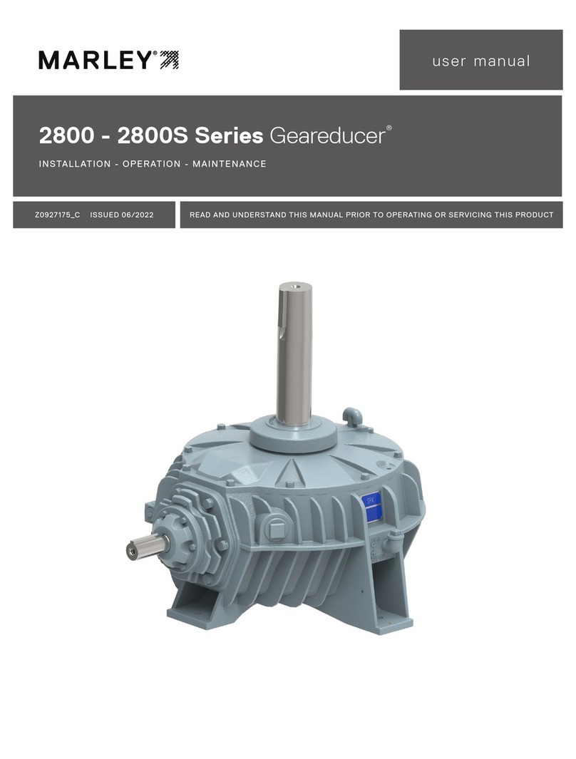
SPX Marley Geareducer 2800 Series User manual
SPX
SPX Marley Geareducer 32.2 Series User manual
SPX
SPX MARLEY Geareducer 2700 Series User manual

SPX
SPX CUES ACCUPOINT MS611 User manual
SPX
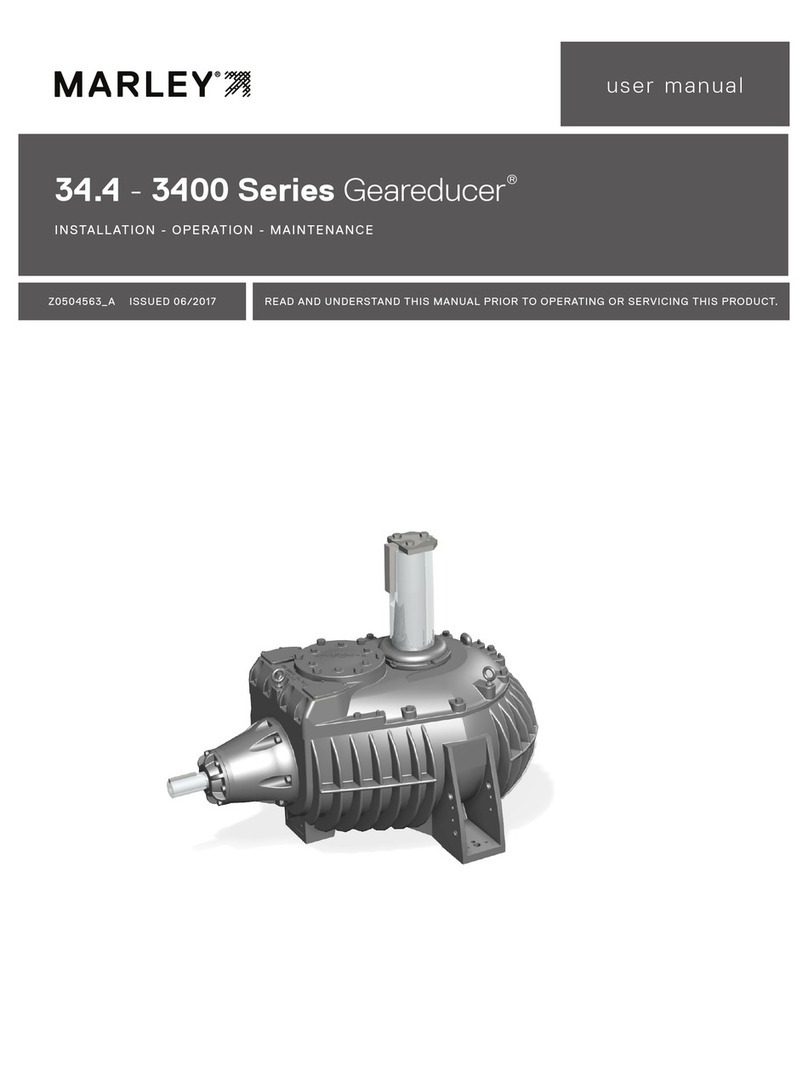
SPX Marley Geareducer 34.4 Series User manual
SPX
SPX APV Cavitator User manual
SPX
SPX RD1000 User manual
SPX
SPX Hankison Trip-L-Trap 505 User manual
SPX
SPX Waukesha Cherry-Burrell Votator II User manual
