Filter Resistance To Air Flow
Air Flow
(CFM)
Pressure Drop
(Inches Water Guage)
MERV 8 MERV 11
600 0.04 0.05
800 0.07 0.08
1000 0.09 0.10
1200 0.11 0.13
1400 0.14 0.17
1600 0.17 0.21
1800 0.20 0.26
2000 0.23 0.31
Application
The air cleaner is to be installed in a forced air
heating, cooling and ventilating system. It should be
installed in the system such that all the system air is
circulated through the air cleaner. Maximum perfor-
mance is obtained when the system blower is set for
continuous operation.
Installation Requirements
Locate the air cleaner in the return air duct next to
the blower compartment. In this location, the blower
motor and the cooling coils will be kept clean. Do
not install the air cleaner in the discharge air
duct. Do not install the air cleaner where it is
directly exposed to UV Lighting.
The unit must be readily accessible for
periodic inspection and replacement of the lter
cartridge to maintain maximum efciency and trou-
ble-free operation. A clean coil will reduce utility cost
by maintaining the coil’s efciency. Failure to replace
the lter cartridge can cause damage to the cooling
system. Allow a minimum of 30” clearance in front of
the access panel for lter cartridge replacement.
Air Cleaner Installation and Maintenance
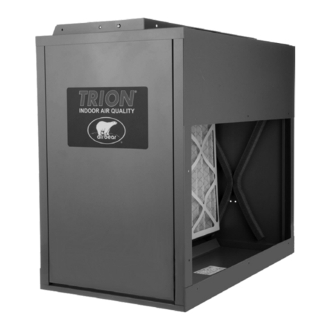
This right angle media air cleaner has been
designed specically for highboy furnaces with
direct installation to the heating and cooling system
return air duct.
The duct opening of the air cleaner is supplied with
an adjustable inlet ange.
The unit is shipped with the ange set at 24”x 8”. If
the incoming duct is 24”x 8”, attach the duct directly
to the ange and secure with sheet metal screws
through the pre-drilled holes.
If the ange requires adjustment to 24”x10”, remove
the ve #6 sheet metal screws securing the ange
to the cabinet. Adjust ange to 24”x10” and secure
with screws. Proceed with installation.
Specications
