Trion Heremidifier Dual Pneumatic User manual

TRION®| www.trioniaq.com
Dual Pneumatic
Atomizing System
READ & SAVE THESE INSTRUCTIONS

Dual Pneumatic
Installation, Operation & Service Manual
2www.trioniaq.com
TABLE OF CONTENTS
I. Warranty ............................................................................................................................................ 3
II. System Operations ..........................................................................................................................4
III. System Components .......................................................................................................................4
IV. System Layout/Installation Guidelines.............................................................................................8
V. Start-Up Procedures.........................................................................................................................10
VI. Operating Instructions .....................................................................................................................11
VII. Maintenance Instructions ...............................................................................................................12
VIII. Troubleshooting Instructions ......................................................................................................... 12
IX. Parts List .........................................................................................................................................15
X. Typical Layouts.................................................................................................................................16
XI. Wiring Diagram................................................................................................................................ 17
IMPORTANT
It is of vital importance that the procedures outlined in this booklet be followed completely. All foreign matter must be
ushed from air and water lines supplying the atomizing heads before the head valves are opened and heads used.
If foreign matter reaches the interior of the heads, each head must be disassembled and thoroughly cleaned - a very
tedious and time-consuming process.
DON’T TAKE SHORTCUTS!
Properly installed and maintained, this system will provide for years of trouble-free service with minimal attention.
Following the steps in the Maintenance section will ensure this. Please read and understand this section. The system
is designed for direct humidication of an area. DO NOT install in duct or air handling systems. Contact TRION for
information on our Herrmidicool system if direct humidication is not possible.

Dual Pneumatic
Installation, Operation & Service Manual
3
www.trioniaq.com
I. WARRANTY
Limited 2-Year Warranty
1. TRION warrants to the buyer or any user during the duration of the Warranty that the TRION/HERRMIDIFIER humidier
described in this manual will be free from defects of material and workmanship for a period of two (2) years.
2. For this Warranty to be effective, this humidier must be installed, operated and maintained in accordance with the Installation
Instructions, Operations and Service Manual(s) supplied with the humidier.
3. In the event of a defect or malfunction in this product during the Warranty Period, user may contact their TRION/HERRMIDIFIER
Representative or TRION Customer Service Department for a Return Material Authorization number. Items tagged with this
number may be returned to the TRION Factory Repair Department for complete reconditioning without charge to the user
for parts or labor. Incidental expenses such as cost of transporting the part/unit to TRION shall be borne by the user. Upon
completion of the reconditioning, the humidier will be returned at no cost to the user. In an effort to keep equipment on line,
TRION may elect to send items out and use the RMA to return alleged defective parts for examination. Credit consideration will
be given upon return and conrmation of improper performance. In either case, items returned without an RMA number will not
be accepted!
4. This Warranty does not cover eld labor for repairs to this humidier or any special, indirect or consequential damages. Some
states do not allow the exclusion or limitation of incidental or consequential damages, so the above limitation may not apply to you.
5. If, after a reasonable number of attempts to do so, TRION is unable to remedy any defects or malfunctions in this humidier,
then the user may elect either a replacement of such product or part which may be defective without charge or a refund at the
buyer’s original purchase price.
6. This Warranty gives you specic legal rights, and you may also have other rights, which vary from state to state.

Dual Pneumatic
Installation, Operation & Service Manual
4www.trioniaq.com
II. SYSTEM OPERATION
The Dual Pneumatic atomizing system operates with air and
water under pressure - air at approximately 30 psi and water
at approximately 32 - 38 psi. Air consumption is gured at
.12 SCFM per lbs. of water atomized per hour. A safety
factor of 20% should be added for any potential line losses.
Operation is fully automatic and controlled by humidistats.
When the relative humidity (RH) level drops below the
setting on the control humidistat, the contacts on the control
humidistat close the circuit, opening the solenoid valve on the
air control section. As soon as pressure builds up sufciently
to atomize, the air pressure switch closes the circuit to the
water solenoid valve, starting water ow. Water can not ow
without adequate air pressure. All valves close if there is a
power failure. The water solenoid will close if there is an air
compressor failure.
When the desired level of RH is reached, the humidistat
breaks the circuit, and all solenoid valves close, shutting
off ow of air and water to the heads. The three-way water
solenoid bleeds off the water pressure instantly, allowing the
water valve seat in the head to close immediately, preventing
any chance of dripping or spitting. At the end of each cycle,
the air pressure is allowed to fall gradually to zero through
the heads, blowing all water from the mixing chamber of the
heads. The stainless steel cleaning needle connected to the
diaphragm cleans the water orice of the heads at the end
of each ON cycle. By completely drying the mixing chamber
of each head, mineral build-up is prevented. This cleaning
is so effective that YEARLY maintenance is typically all that
is required!
III. SYSTEM COMPONENTS
A Dual Pneumatic atomizing system consists of atomizing
nozzles, control sections, humidistats, and an adequate air
and water supply.
Atomizing Heads
Atomizing heads are available in capacities of 6, 8, 10, 12, or
15 lbs. of water per hour.
The proper head capacity for a given project is selected on
the basis of installed height of the head above the oor, clear
area available for spray patterns to evaporate, and conditions
to be maintained in the humidied space.
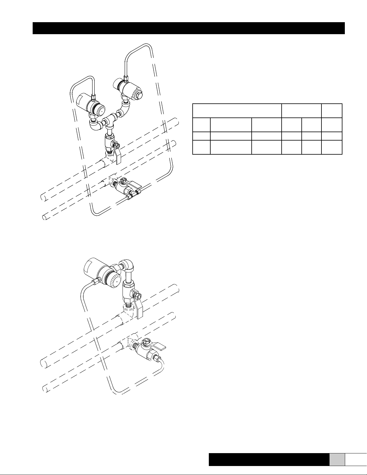
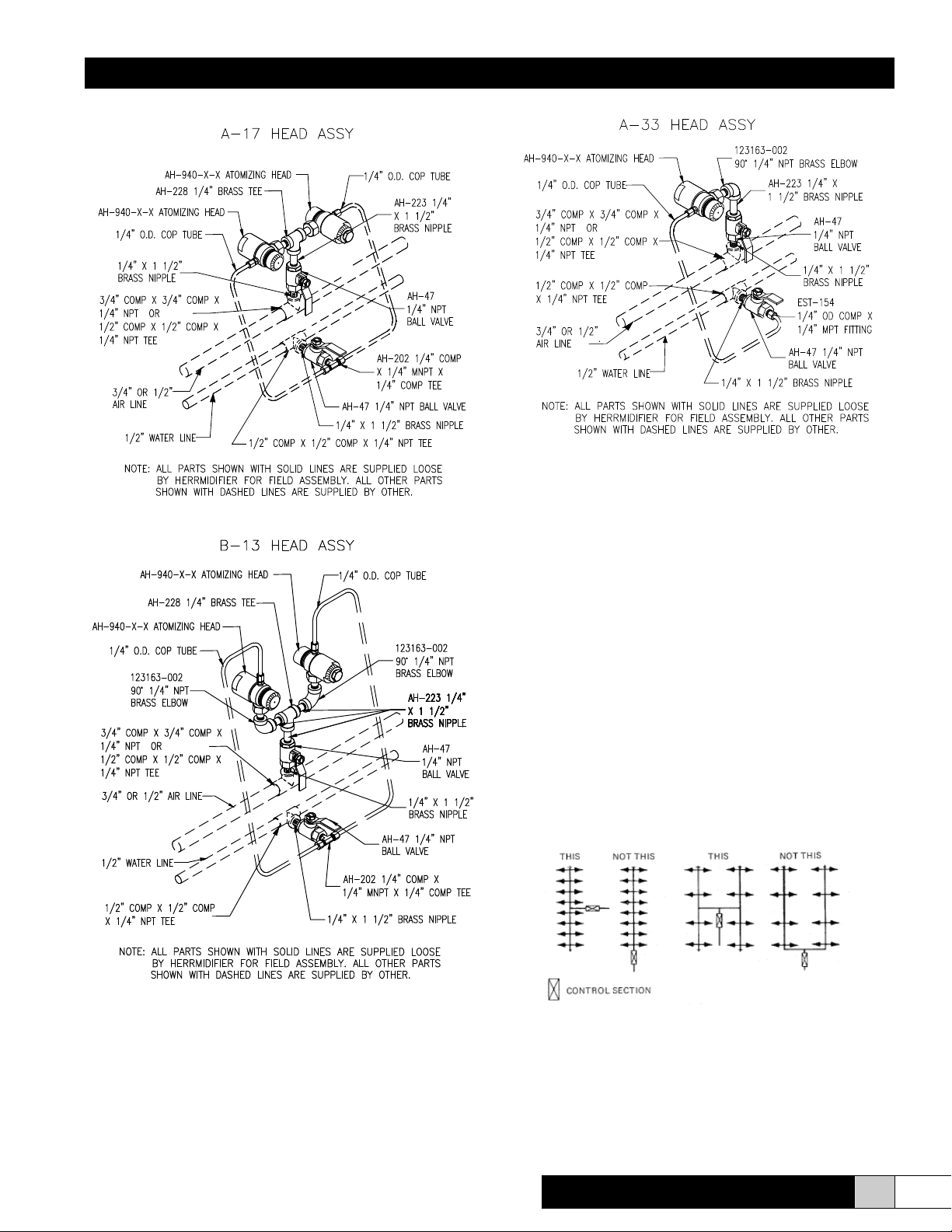
Atomizing head assemblies are available in three versions.
The A-17 assembly (Figure 1) consists of two identical
capacity heads spraying in opposite directions and is
used when areas are clear of obstacles in both directions
and where distances shown in installation section can be
observed.
The B-13 assembly (Figure 2) consists of two identical
capacity head assemblies discharging in the variable
directions of discharge.
Figure 1. A-17 Head Assembly
Dual Pneumatic
Installation, Operation & Service Manual
5
www.trioniaq.com
The A-33 assembly (Figure 3) is a single head assembly for
use in restricted areas.
Control Sections
The control sections provide the following features:
• Regulate plant air and water to desired operating pressures
• Monitor the ow of air and water to the heads via
solenoid valves
• Air pressure switch prevents ow of water to heads until
there is sufcient air pressure for atomization
• Dripless operation and automatic purging of minerals
from heads during system cycling
The standard air control sections are available in two
different sizes, and the water control section is available in
one size (see pages 6-7).
Minimum Pipe
Size to Heads
Size Pipe
Connections
Max.
Capacity Air Water Water
Drain
1/2” 1/2” FPT 240 lbs/hr 3/4” 1/2” 1/2”
3/4” 3/4” FPT Air
1/2” FPT Water 500 lbs/hr 3/4” 1/2” 1/2”
Controls
The standard Dual Pneumatic atomizing system requires
ON-OFF humidistats for operation. Controls may be
provided by others, in which case, consultation with TRION
is essential to ensure proper operation.
Several control options are available from TRION. The
standard system consists of a control humidistat and high-
limit (safety) humidistat. (A hygrometer is optional with any
Dual Pneumatic system.)
For critical applications where extreme tolerances or
temperature and humidity requirement demand it, an
electronic humidistat may be required.
Air Supply
Plant air can be used if supply is adequate. All heads use
12 SCFM of air per 100 pounds of atomized water delivered.
However, a safety factor of 20% should be added for line losses.
Air should run through a minimum of a cyclone type moisture
separator and a 0.5 micron coalescing lter (supplied by
others) to ensure that it is dry and oil-free before it reached
the air control section and the heads.
An air compressor used only for humidication can be
operated at 60-70 psi. No need to run at 125-150 psi, as
this would waste energy.
Water Supply
With any air/water atomization system, any solids in the
water will be distributed into the air during atomization.
Always check the water quality before installing an air/water
atomization system. TRION, or your local lab, can perform
this test for you. The Dual Pneumatic atomizing system is
available for raw and demineralized water supplies. With
your water analysis, you and your TRION/HERRMIDIFIER
representative can determine what, if any, water treatment
is required.
Figure 2. B-13 Head Assembly
Figure 3. A-33 Head Assembly

Dual Pneumatic
Installation, Operation & Service Manual
6www.trioniaq.com
Figure 4. AH-1020 - Air Control Section
For System Capacities up to 240 lbs./hr.
Approximate Measurements: 23” L x 6” H
Figure 5. AH-1050 - Air Control Section
For System Capacities up to 500 lbs./hr.
Approximate Measurements: 32” L x 10” H
Dual Pneumatic
Installation, Operation & Service Manual
7
www.trioniaq.com
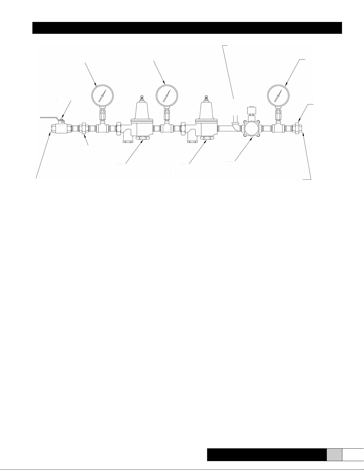
OVERALL DIMENSIONS
33"L x 8"H
n
THREE-WAY
WATER VALVE
Figure 6. AH-1021 - Water Control Section
To be Used with AH-1020 or AH-1050 Air Control Sections
Approximate Measurements: 33” L x 8” H
Dual Pneumatic
Installation, Operation & Service Manual
8www.trioniaq.com
IV. SYSTEM LAYOUT AND INSTALLATION
Be sure all parts are used in the system in their proper order
and direction of ow. DO NOT leave out any parts because
they have a different function in the operating system.
Layout of Head Assemblies
1. Be sure all ttings are in their proper place in all head
assemblies. (Reference drawings on the next page).
Do not add parts to these assemblies without permis-
sion from TRION. Head assemblies for systems using
demineralized water supplies will have the same com-
ponents as shown on this page. However, their materi-
als may be different, e.g. PVC or stainless steel.
2. The smallest spray pattern is experienced at low levels
of relative humidity and high temperatures, and the
largest pattern at the high levels of relative humidity and
low temperatures. If the head discharges directly into a
warm air stream that is moving in the same direction as
the head spray discharge, any size head can be used.
(This is found when heads are located at discharge
grilles of an air handling system.) The chart below is a
good guide to follow in selecting proper head capacity.
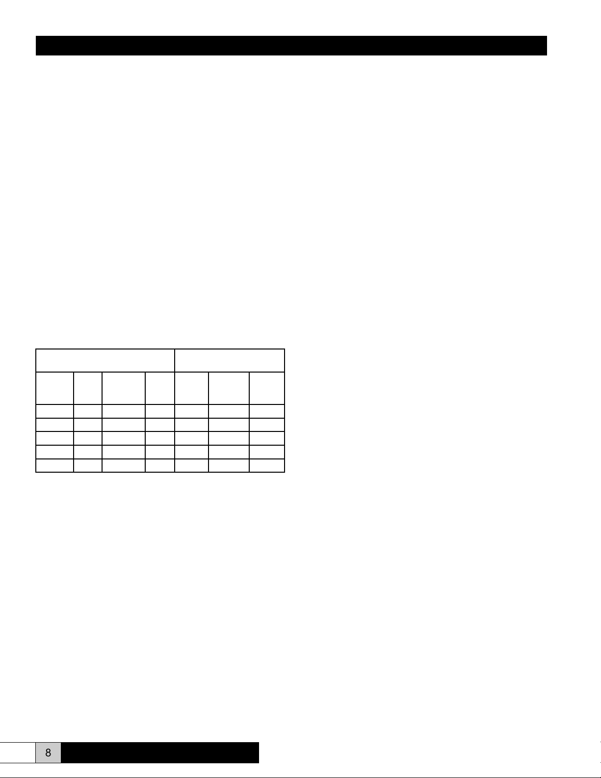
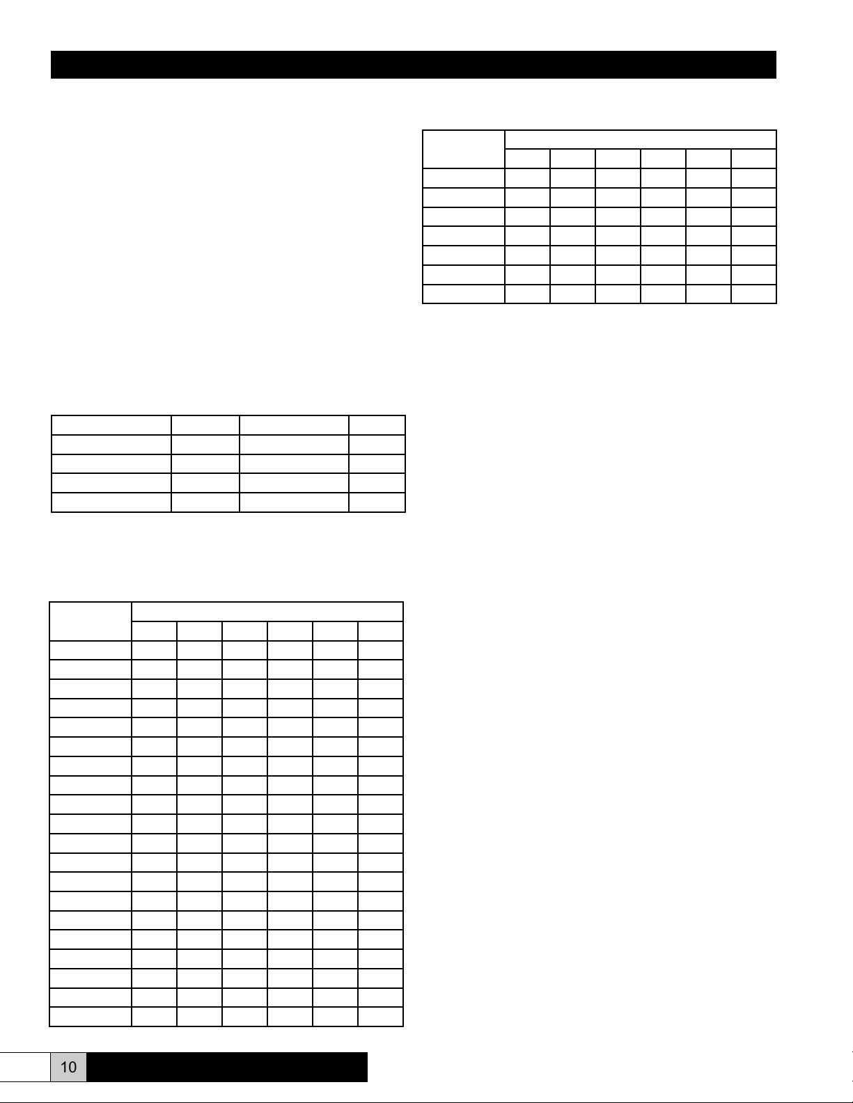
Spray Visible to This Point
from Hd in Med
Head
Cap.
Inst.
Hgt.
Use w/
RH Lvls
Max.
Spray
Dia.
Low
(<45%)
RH
Med
(45-60%)
RH
High
(>60%)
RH
6 lbs/hr Any Any 2.5 ft 10 ft 13 ft 16 ft
8 lbs/hr 12 ft+ Any 2.5 ft 10 ft 13 ft 16 ft
10 lbs/hr 14 ft+ Up to 85% 3 ft 11 ft 14 ft 17 ft
12 lbs/hr 16 ft+ Up to 75% 3.5 ft 12 ft 15 ft 18 ft
15 lbs/hr 18 ft+ Up to 65% 4 ft 13 ft 17 ft 21 ft
Note: The above table applies to installations at normal temperatures
(68°-75° F) and with no forced air movement in the area.
For temperatures 50°-67° F, use rst smaller head size. For
temperatures 32°-49° F, use second smaller head size. For example:
18 ft installed height @ 70° - 65% RH: Select 15 lb/hr head
@ 55° - 65% RH: Select 12 lb/hr head
@ 36° - 65% RH: Select 10 lb/hr head
Important: Obstructions such as columns, stacks of materials, etc. may
indicate that even a lower capacity head might be preferred. Good
air movement in the space results in more rapid evaporation of the
atomized water into the vapor state with shorter spray patterns being
visible. However, very high air movement can carry droplets causing
them to impinge on objects - especially at high levels of RH.
3. The number of head assemblies required should be
calculated and then properly arranged to provide
uniform coverage.
4. Do not locate heads in a manner where the spray will
contact a wall, machine, unit heater, pipes, columns,
conveyer, lights, wires, or obstructions. Distance from
such obstructions should not be less than the maximum
visible spray pattern length. (See chart above.)
5. Heads should be located so that the discharge is away
from personnel to ensure that droplets and evaporative
cooling will not cause discomfort.
6. Do not locate heads in such a manner that they
discharge directly towards one another, unless they
are further apart than twice the maximum distance the
spray pattern is visible. (See chart above.)
7. In all cases, the heads can be further apart than the
maximum visible spray pattern. Due to Dalton’s Law
of Partial Pressures, the water vapor travels throughout
the area very rapidly, and a uniform level of relative
humidity will be attained and maintained automatically.
8. Pipe runs should be kept as short as possible.
9. Head assemblies must have less than 100 feet of pipe
run between the control section and the farthest head
assembly.
10. Head assemblies A-17 and A-33 should be a minimum
of 4 ft. apart on air and water pipes. Head assembly
B-13 should be mounted a minimum of 8 ft. apart.
11. It is recommended that the heads be located above
the air and water lines. However, if this is not practical
for installation or aesthetic reasons, the heads may be
hung below the air and water lines. In this case, the 3/4”
air lines should be run on the bottom and the 1/2” water
line run on top. Air and water takeoffs must always
come of the top of the lines regardless of the position of
the heads. The heads may NEVER be positioned more
than 18” vertically from the air and water lines.
12. Heads installed near a wall with the spray directed away
from the wall should be kept at least one foot away (from
the wall) to allow for start-up adjustment on the heads.
13. Use ONLY copper or plastic air and water lines. DO NOT
USE IRON, STEEL, OR GALVANIZED PIPE, as these
types are especially susceptible to scaling and aking,
which can cause jamming of the head mechanism. If
iron, steel, or galvanized piping must be used before
the system, a lter MUST be installed at the transition.
14. Air and water lines MUST be located so that a straight
level run can be maintained from the control section
to the heads. Avoid excessive curves and NEVER
allow loops in the piping, as these will trap air and
debris. ALL HEADS MUST BE LEVEL AND AT THE
SAME ELEVATION. If loops are unavoidable in routing
piping, air vents must be installed at the high point of
the vertical drop.
15. Hose bibs, supplied by others, must be used on the
ends of ALL water and air lines for each in maintaining
the system.
Dual Pneumatic
Installation, Operation & Service Manual
9
www.trioniaq.com
Control Sections
1. Control sections should be placed where they are easily
accessible and protected from trafc damage.
2. Control sections should be located level with or below air
and water lines, never above. Where heads are located
high, it is advisable to locate the control section at a
height that is accessible with a small ladder. The 1/2”
and 3/4” control sections can be mounted a maximum of
30’ below the height of the heads. If the control sections
are mounted at a level different from the heads, it is
recommended that air and water gauges be placed on
the lines at the height of the heads because the pressure
readings at the control sections and heads will differ.
3. Always be sure the drain from the 3-way solenoid extends
a minimum of 3” above the heads, pipe run, or control
sections. It is advisable to place a union on the drain line
near the control section. If the drain loop is not used,
water will siphon out of the system and allow air into the
water lines causing system malfunction.
4. Feed lines from the control section to heads should be
placed at the midpoint of the pipe run to equalize pressure
and ow in the system.
Control Location
Humidistats are to be at a protected location, on a column or
inside wall. They should be located so they are not affected
by the discharge from the heads, heaters, or air conditioners,
and they should be protected from direct sunlight. There
must, however, be sufcient clearance around the humidistats
Dual Pneumatic
Installation, Operation & Service Manual
10 www.trioniaq.com
Loss of Water Pressure Due to Friction
in psi per 100 ft. of Type “K” copper tube at 60 PSIG
Flow Gals.
per Min.
Pipe Size
1/2” 3/4” 1” 1 1/4” 1 1/2” 2”
1 1.30 0.25 0.05 - - -
2 4.50 0.85 0.23 0.07 - -
3 9.00 1.70 0.45 0.15 0.063 -
4 15.00 2.80 0.75 0.25 0.10 -
5 22.00 4.20 1.10 0.36 0.16 0.042
6 31.00 5.80 1.50 0.50 0.22 0.058
7 40.00 7.50 2.00 0.65 0.28 0.073
For longer or shorter lengths of pipe,the friction loss is
proportional to the length.
Example: AIR LINE 500 ft. One half of the above
4,000 ft. Four times the above
WATER LINE 50 ft. One half the above
400 ft. Four times the above
5. Follow start-up procedure EXACTLY. Repeat the start-up
procedure every time the system is drained or cleaned.
V. START-UP PROCEDURES
1. CHECK INSTALLATION WITH THE LAYOUT
DRAWING. Be sure that the equipment has been
installed exactly as laid out on the system drawing
- location of head assemblies, control sections,
humidistats, etc. and that the proper size pipe has
been used on all air and water supply lines as well as
drain lines. (Frictional losses and pressure drops were
considered in making the layout.)
2. CLOSE ALL AIR AND WATER VALVES AT EACH
HEAD ASSEMBLY. It is vitally important that no foreign
matter in the supply lines - air and water - gets into the
heads.
3. CLEAN MAIN SUPPLY LINES TO CONTROL
SECTIONS. Close air and water valves on the incoming
side of all control sections. Start the air compressor.
Open the main valves at the air compressor and water
source. Break the unions just ahead of the incoming air
and water pressure gauges of the control sections. AIR
MAIN LINE: Put on safety glasses. Place a cloth over the
open air line to catch any ying debris. Place a bucket
over the end of the air line. Slowly open the valve and
let the air line blow until clean. DO NOT LOOK INTO
THE BUCKET WHILE THE AIR IS BLOWING. Close the
valve and retighten the union securely. WATER MAIN
LINE: Repeat the above procedure for the water line.
Clean lines to all control sections as described above.
4. CHECK ELECTRICAL WIRING OF CONTROLS. Set
the SAFETY humidistat to maximum. Set the CONTROL
humidistat to 20%. NOTE: If only one humidistat is used,
set to 20% or switch it to OFF. Open air valve ONLY to
feed air to control section. Do NOT open water valve.
to properly sense the relative humidity of the surrounding air.
(See Wiring Diagram on page 17.)
Other Considerations
1. Air must be free of oil and water. It is wise to place lters
on both the air and water feed lines ahead of the control
sections. TRION recommends the use of a moisture
separator and trap and a coalescing lter on the air line.
2. To prevent condensation on uncovered cold water pipes
in the system, it is advisable to consider using aftercooler
water from the air compressor in the humidication
system. If this is not practical, a heater for the system’s
water supply may be used.
3. If the water supply pressure uctuates and doesn’t
maintain 50 psi at the highest level of a head assembly,
it will be necessary to supply a water pressure booster
pump or bladder tank for the system. Consult TRION for
assistance in sizing pump and tank.
4. With extremely large systems, supply piping should be
sized as follows:
System Cap. - Water MIN. Water System Req. - Air Min. Air
Up to 1,000 lbs/hr 1/2” 10 - 24 CFM 3/4”
1,000 to 2,000 lbs/hr 3/4” 24 - 45 CFM 1”
2,000 - 3,000 lbs/hr 1” 45 - 70 CFM 1 1/4”
Over 3,000 lbs/hr 1 1/4” 70 - 100 CFM 1 1/2”
Supply piping should be sized to control sections so as to
minimize pressure drop in accordance with table below.
Cu. Ft. Free
Air per Min.
Pipe Size
1/2” 3/4” 1” 1 1/4” 1 1/2” 2”
10 6.50 0.99 0.28 - - -
20 23.90 3.90 1.31 0.25 0.11 -
30 58.50 9.01 2.51 0.57 0.26 -
40 - 16.00 4.45 1.03 0.46 -
50 - 25.10 6.96 1.61 0.71 0.19
60 - 36.20 10.00 2.32 1.02 0.28
70 - 49.30 13.70 3.16 1.40 0.37
80 - 64.50 17.80 4.14 1.83 0.49
90 - 82.80 22.00 5.23 2.32 0.62
100 - - 27.90 6.47 2.86 0.77
125 - - 48.60 10.20 4.49 1.19
150 - - 62.80 14.20 6.43 1.72
175 - - - 19.80 8.72 2.38
200 - - - 25.80 11.40 3.06
250 - - - 40.40 17.90 4.78
300 - - - 58.20 25.80 6.85
350 - - - - 35.10 9.36
400 - - - - 45.80 12.10
450 - - - - 58.00 15.40
500 - - - - 71.60 19.20
Loss of Air Pressure Due to Friction
in psi per 1000 ft of pipe at 100 PSIG
Dual Pneumatic
Installation, Operation & Service Manual
11
www.trioniaq.com
Adjust air pressure regulator of control section to 30 psi.
Slowly move the CONTROL humidistat to a higher RH
until you hear a “click” indicating the 2-way solenoid valve
on the air control section has opened. NOTE: If only one
humidistat is used, follow above procedure slowly raising
RH setting, or if switch is used, turn to ON. Reduce the
setting on the SAFETY humidistat until you hear a click
indicating the 3-way solenoid on the water line has closed.
(If no safety humidistat is used, skip this step.) Open the
AIR valve ONLY on one pair of heads. There should be a
constant ow of air from the heads with no ow of water.
This will indicate that the controls for the control section
are properly wired. Make any corrections needed. Close
the air valve after determining wiring is correct. Repeat
the above at each control section in the system.
5. CLEAN DISTRIBUTION LINES FROM CONTROL
SECTIONS TO HEAD ASSEMBLIES. IMPORTANT:
Be sure all air and water valves at head assemblies are
closed (Step 2). AIR LINES: Put on safety glasses. With
CONTROL humidistat ON and air valve at control section
open, place bucket and cloth over hose bib at end of each
air line and slowly open the hose bib and allow line to
blow clean. DO NOT LOOK INTO BUCKET WHILE AIR
IS BLOWING. Close hose bib. Repeat on all air lines
from each control section. WATER LINES: (Air valve at
control section should be open.) Set SAFETY humidistat
at maximum and CONTROL humidistat ON. Open water
valve at control section. Place bucket or hose on ends
of water lines and slowly open hose bibs. Allow water to
ow until clean. Throttle valve to avoid splashing. Close
hose bib. Close air and water valves at control section.
Repeat on all water lines from each control section.
6. STARTING THE SYSTEM. Close air and water valves
at all control sections. Open air valves only at all head
assemblies. Set humidistats high enough to assure
system operation. Open AIR valve at control section.
With air owing through heads, adjust primary air
pressure regulator (or compressor) to maintain 55 psi.
Adjust control section air pressure regulator to 30 psi.
With water valve open at water source, open the control
section water valve and the water valve of the ONE
head assembly located the GREATEST distance from
the control section. Adjust the primary water pressure
reducer to provide 45-50 psi to the control section.
Adjust control section water valve to provide 32-38 psi
to heads. Open the water valve at each head assembly,
checking and correcting for air and water leaks as you
go. CAUTION: Never let water pressure get below
air pressure as air will then get into water lines and
necessitate bleeding of lines. Repeat procedure on all
control sections and primary reducers. Normally, with all
heads operating, it will be necessary to again adjust the
primary water pressure reducer to 45-50 psi and control
section water pressure regulator to 32-38 psi. Tighten
the locknut on all WATER pressure regulators - primary
and control section. All further adjustments will be made
on air controls and at heads. With the entire system in
full operation, check for leaks in all air and water lines,
ttings, connections, valves, control sections, and head
assemblies. Correct as required.
7. FINAL ADJUSTMENTS TO HEADS. Remove cap
(253206-00X) of each head. This cap is at the non-
discharge end of the head and covers the head adjusting
“spring tension nut” (253207-00X). Slowly turn this
adjusting nut in a clockwise direction until no water is
discharged by the head. Use care to avoid damage to
the valve seat. Then, back off this adjusting nut TWO full
turns counter clockwise. This may result in an excessively
heavy spray, but this will be adjusted later in the control
section. Replace cap. Repeat this operation on every
head on the system. NOTE: Maintain air pressure at 30
psi and water pressure at 32 - 38 psi. Do NOT let air
pressure exceed water pressure.
8. BALANCING THE SYSTEM. The nal and most
important adjustment will be made at the air pressure
regulator of each control section. Adjust the air regulator
to 30 psi; adjust water pressure for proper head capacity.
Increasing the air pressure to the heads results in smaller
droplet size in discharge pattern - and vice versa. Spray
pattern should be visible to at least 10’ from the head to
assure rated capacity. With the system in full operation,
adjust the safety humidistat to 10% above the desired
level. Remove the cover of this humidistat and set the
low and high limit stops to the RH setting so the setting
cannot be changed. Replace cover. Move the CONTROL
humidistat setting alternately lower and higher to cycle
the system OFF and ON several times until all gauges
become repetitive in action and readings.
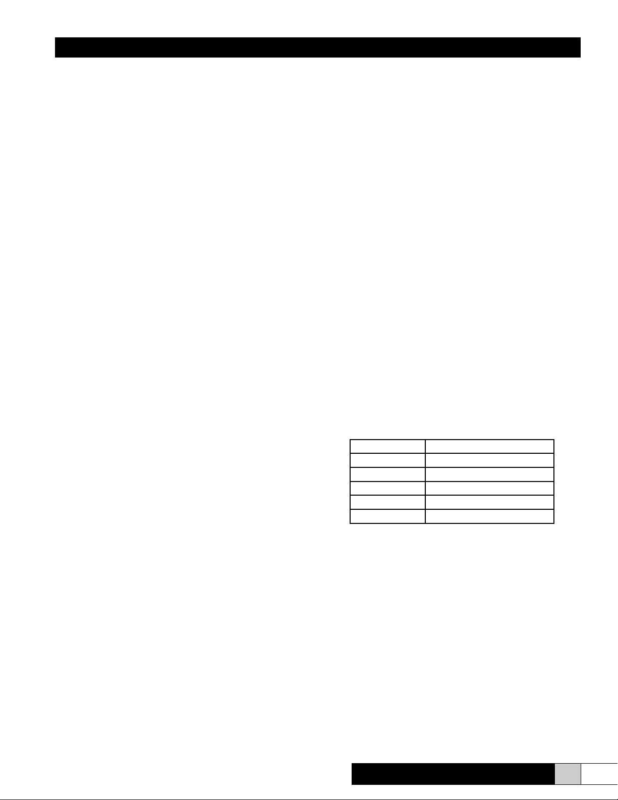
Water Pressure Settings
Head Capacity Water Pressure Setting (PSI)
6 32
8 38
10 33
12 35
15 37
Note: A new system may require some adjustment until all parts are
properly seated during break-in. This period may last about two weeks.
After that, adjustments may not be required but should be checked on a
regular schedule. Set the humidistat at the desired level.
CAUTION:
1. Do not balance the system by adjusting individual heads. Each
head has been adjusted to provide its design capacity.
2. Do not throttle any valves at control sections or head assemblies to
get nal adjustment.
VI. OPERATING INSTRUCTIONS
The Dual Pneumatic Atomizing System utilizes air and water
under pressure to atomize the water into tiny droplets (2-
15 microns with an average of 7.5). These droplets rapidly
evaporate to a gaseous state to raise the level of relative
humidity.

Dual Pneumatic
Installation, Operation & Service Manual
12 www.trioniaq.com
Each Dual Pneumatic Atomizing System is custom designed
for each application to maintain the level of relative humidity
desired under the conditions to be maintained with the
equipment as it exists in the area at the time. If ANY
conditions change, the demand load for humidication can
be affected.
Once the system is installed, checked out, and started in
accordance with the instructions contained in this manual,
operation is completely automatic to maintain the level
of relative humidity. With air and water supplied to the
equipment, the system cycles ON and OFF as needed.
Set the desired level of RH on the control humidistat, 10%
more on the safety humidistat, and you can walk away and
forget it.
If there is a POWER FAILURE, the system automatically
shuts off.
If there is an AIR COMPRESSOR FAILURE, the system
automatically shuts off.
If there is a FAILURE OF THE WATER SUPPLY, the heads
will blow air.
If the water supply PRESSURE is lost or reduced, the heads
will “sputter”.
If the CONTROL humidistat fails to shut off the system, the
SAFETY humidistat will shut off the water to the heads at 10%
above the desired level of RH. You cannot over-humidify to
any greater extent than the 10%.
The atomizing heads operate drip free and are self-cleaning
and self-purging at the end of every ON cycle. The system
is designed to go ON and OFF. Without this cycling, the
cleaning and purging action is lost.
The system can be started and stopped by merely operating
the control humidistat.
All humidication equipment needs periodic maintenance.
The procedure for the Dual Pneumatic System is spelled out
in that section of this manual. Otherwise, the operation is
fool-proof and dependable.
VII. MAINTENANCE INSTRUCTIONS
The Dual Pneumatic Atomizing System requires little
maintenance to keep it operating properly. In hard water
areas and dusty atmospheres, more frequent attention will
be required.
NORMAL MAINTENANCE required is as follows.
• AIR COMPRESSOR: Follow the air compressor
manufacturer’s instructions.
• ATOMIZING HEADS: Clean dust and debris from the
OUTSIDE of the heads as required to keep the spray
pattern adequate. At least ONCE A YEAR, remove the
atomizer nozzles (AH-941-X-X). Clean these nozzles in
a weak acid solution. Do NOT use a wire or other object
that will score the nozzle or its orice.
• AIR & WATER LINES: Blow out all supply lines at least
ONCE A YEAR using the procedures covered under
start-up of the system in this manual. Check all joists
and valves for leaks ONCE A YEAR.
• STRAINERS: Strainers on air and water controls (both
primary regulators and control section regulators) should
be cleaned ONCE A YEAR and replaced as required.
Strainer screens (AH-21) in the strainer union assembly
(AH-17) of each head should be cleaned ONCE A YEAR.
If air strainers are dirty or oily, it may be necessary to
install an air dryer or after cooler on the compressor or a
separator on the air line.
• HUMIDISTATS: Calibration should be checked with a
dependable psychrometer at least ONCE A YEAR and
adjusted as needed.
• HYGROMETERS: (RH indicators) Use psychrometer to
check for accuracy.
• PRESSURE REGULATORS: Air and water (primary
and control sections) - check operation at least ONCE A
YEAR to be sure regulation to desired pressures is being
maintained properly.
• SOLENOID VALVES: Air and water (control sections) -
check operation at least ONCE A YEAR to be sure their
operation is proper and valves do not leak.
After the removal and re-installation of heads and control
sections, ALWAYS follow the start-up procedure to be sure
all foreign matter is ushed from the lines and none reaches
the heads.
Your system will last indenitely if properly maintained.
VIII. TROUBLESHOOTING
HEAVY SPRAY PATTERN (Droplets too large)
ALL HEADS served by one control section: either this is
caused by too low a setting on the air pressure regulator of
the air control section, which calls for slightly increasing the
air pressure - or too high a setting on the water regulator
of the water control section, which requires decreasing the
water setting slightly.
NEVER LETAIR PRESSURE EXCEED WATER PRESSURE.
INDIVIDUAL HEADS: These heads are not getting enough air.
1. Foreign matter may be clogging the screen (AH-21) in
the air strainer union (AH-17) of the head.
2. One or more heads served by the same control section
may have been IMPROPERLY ADJUSTED by throttling
the valves at the head assembly. No valves should ever
be throttled!
3. Water nozzle (AH-942-X) orice may have been enlarged
due to bent cleaning needle on diaphragm (AH-10).

Dual Pneumatic
Installation, Operation & Service Manual
13
www.trioniaq.com
Replace parts as required.
4. Atomizer nozzle (AH-941-X-X) orice may have been
enlarged due to improper cleaning or dirty air. (See
Maintenance section.) Replace parts as required.
SPRAY PATTERN TOO LIGHT
ALL HEADS served by one control section: either this is
caused by too high a setting on the air pressure regulator of
the air control section, which calls for slightly decreasing the
air pressure - or too low a setting on the water regulator of
the water control section, which requires increasing the water
setting slightly.
INDIVIDUAL HEADS: Heads are not getting enough water.
1. Water valve at head may have been throttled. No valves
should ever be throttled! Adjust head and shown in Step
7 of start-up procedure.
2. Foreign matter may be restricting water ow in the water
nozzle (AH-942-X). Shut off air and water valves at head
assembly. Remove atomizer nozzle (AH-941-X-X) and
water nozzle (AH-942-X) with wrench. DO NOT use wire
or hard object that will score inside.
SPUTTERING HEADS
ALL HEADS served by one control section: air pressure at
heads exceeds water pressure at heads.
• Adjust air and/or water pressure at control section so that
air pressure is about 2 psi lower than water pressure.
• Three-way solenoid on water control section may be
malfunctioning to allow water to leak down drain port
when system is operating. This may be caused by dirt
under the drain valve seat or a bad valve seat on the
drain side of the three-way solenoid. NOTE: The drain
side of the three-way solenoid should open only when
the system shuts off. Approximately one cup of water
should be drained from the system between cycles. A
greater amount may be a sign of air trapped in the water
line. Review start up procedure.
INDIVIDUAL HEADS:
1. Water valve supplying head assembly has been throttled.
No valves should ever be throttled.
2. Head improperly adjusted. Follow Step 7 of start-up
procedure.
3. Part malfunctioning inside head. Check diaphragm (AH-
10), spring (AH-8), and valve disk (AH-16). Correct as
required.
INOPERATIVE HEADS (No air or water)
ALL HEADS served by one control section:
1. These heads shut down because control humidistat is
satised.
2. If proper RH level has not been attained, check calibration
of the control humidistat and adjust if required. Use a
dependable psychrometer.
3. Air and water valves serving the control section are not
open.
4. Electric current not owing to central section. Check
wiring and supply lines.
5. Compressed air is not reaching the control section.
Possible compressor failure.
INDIVIDUAL HEADS:
1. Be sure air and water valves at head assembly are
fully open.
2. Indicates diaphragm (AH-10) may be ruptured or
leaking OR water and air ports clogged. Close air and
water valves at head assembly. Remove rear part of
head (Bonnet, 253209-00X) with a wrench. Examine
the diaphragm (AH-10), spring (AH-7), and valve disc
(AH-16). Replace any bad parts. If these parts are
OK, reassemble the head. CAUTION: Use care in
reassembling so that cleaning needle is not damaged.
Remove atomizer nozzle (AH-941-X-X) and water nozzle
(AH-942-X). Clean these nozzle ports with air pressure
or as recommended under maintenance. DO NOT use
a wire or any object that will score the inside or port of
the nozzles. Reassemble the head, open the air valve
of the head assembly, then the water valve of the head
assembly and adjust spray pattern. (See Step 7 of the
start-up procedure.)
AIR WITHOUT WATER
ALL HEADS served by one control section: be sure water
valve at control section is open. RH exceeds that set on the
SAFETY humidistat. This shuts off water to all heads but
allows air to ow. Correct this condition by:
1. Set SAFETY humidistat higher than CONTROL
humidistat.
2. Make sure CONTROL humidistat is functioning to start
and stop system.
3. Check calibration of BOTH humidistats with a dependable
psychrometer.
4. Check the setting on the air pressure switch and be sure
that the switch is cutting in at 26 psi and out at 20 psi of
air pressure. Adjust accordingly by setting high end rst
at 26 psi and then turning low end up against it.
INDIVIDUAL HEADS:
1. Water cut-off at valve at head assembly.
2. Water nozzle (AH-942-X) plugged with foreign matter.
Correct as above under “Spray Pattern Too Light”.
HUMIDITY LEVEL TOO LOW
1. Be sure CONTROL humidistat is set at desired RH.
2. Check calibration of CONTROL humidistat and
HUMIDITY INDICATOR with dependable psychrometer
and adjust as required.
3. Be sure humidistat is not being “inuenced” by the spray
pattern of a head coming too close to it. Correct as
required.
4. Be sure humidistat is not being “inuenced” by a cold air
stream blowing directly on it. Correct as required.
5. The temperature of the air in the area being humidied
may be different for than that for which the system was
designed. If so, AND this changed temperature will now

Dual Pneumatic
Installation, Operation & Service Manual
14 www.trioniaq.com
be maintained, additional humidication equipment will
now be required. Call your TRION/HERRMIDIFIER
representative.
6. Exhaust, make-up air, or cooling equipment may have
been added to the area since the system was designed.
These add to the maximum demand load, and additional
humidication equipment will now be required. Call your
TRION/HERRMIDIFIER representative.
HUMIDITY LEVEL TOO HIGH
1. Be sure CONTROL humidistat is set at desired RH (and
SAFETY humidistat about 10% higher than control).
2. Check calibration of CONTROL and SAFETY humidistats
as well as the RH indicator with a dependable
psychrometer and adjust as required.
3. Be sure humidistat is not being “inuenced” by a hot air
stream blowing directly on it. Correct as required.
EXCESSIVE AIR CONSUMPTION
Dual Pneumatic Atomizing Systems consume a maximum of
12 CFM of free air delivery per 100 lbs. of water atomized
per hour.
1. Check ALL air line joints, valves, and valve stems
throughout entire compressed air system (not just the
Dual Pneumatic system) for leaks and correct as required.
2. Air compressor may not be delivering rated capacity
because of maintenance work needed.
3. Other air operated equipment in plant may be consuming
more air than it should because of maintenance work
needed.
4. Air operated equipment may have been added to the
plant which caused the total air consumption needed to
exceed rated capacity of the air compressor.
Dual Pneumatic
Installation, Operation & Service Manual
15
www.trioniaq.com
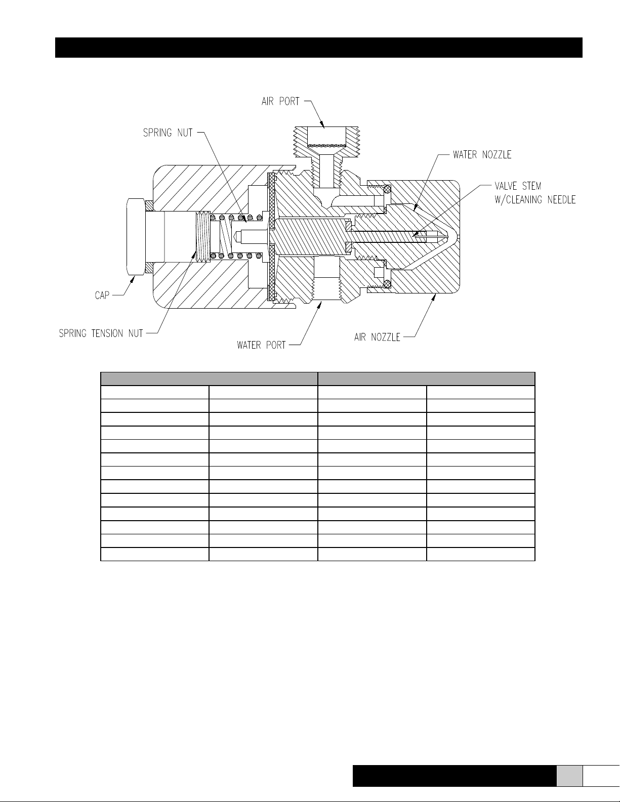
IX. PARTS LIST
Brass Nozzle Consists of: SS Nozzle Consists of:
Part # Description Part # Description
253205-001 Nozzle Body 253205-002 Nozzle Body
253209-001 Bonnet 253209-002 Bonnet
AH-941-1-”X” Air Nozzle AH-941-2-”X” Air Nozzle
AH-942-1(R) Water Nozzle AH-942-2(R) Water Nozzle
253206-001 Cap 253206-002 Cap
253207-001 Spring Tension Nut 253207-002 Spring Tension Nut
253208-001 Spring Nut 253208-002 Spring Nut
AH-12(R) Valve Stem w/ Needle AH-12(R)-SS Valve Stem w/ Needle
AH-19A Air Port AH-19ASS Air Port
AH-18A Union Tail Piece AH-18ASS Union Tail Piece
AH-20 Union Nut AH-20SS Union Nut
AH-1RK (Note 1) Rebuild Kit AH-1RK Rebuild Kit
“X” Denotes nozzle rating in pounds/hour (6, 8, 10, 12 or 15 lb/hr).
Notes:
1. AH-1RK Kit includes: Diaphragm, AH-122 “O” Ring, AH-14 Air Nozzle Gasket, AH-15 Water Nozzle
Gasket, AH-16 Valve Disk, AH-21 Strainer Screen, AH-23 Diaphragm Washer, AH-8 Spring, FV-17-
1 Union Washer
2. Always specify nozzle rating in lbs/hr on any nozzle parts order.
3. The notation for (R) is used when capacity of head is 6 or 8 lbs/hr.

Dual Pneumatic
Installation, Operation & Service Manual
16 www.trioniaq.com
X. TYPICAL LAYOUTS
Dual Pneumatic
Installation, Operation & Service Manual
17
www.trioniaq.com
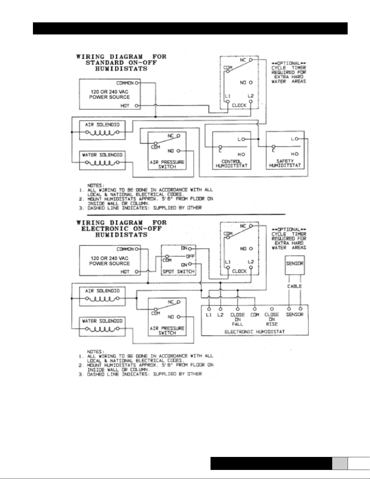
XI. WIRING DIAGRAMS

© 2018 TRION. All Rights Reserved.
TRION®
101 McNeill Rd. | Sanford, NC 27330
Form No. AH-22 Rev. 06/18
Table of contents


