triOS 02A100 8 Series User manual
Wiper W55 V2
1
TriOS Mess- und Datentechnik GmbH · Bürgermeister-Brötje-Str. 25 · D-26180 Rastede · Germany
fon: +49 (0) 4402 69670 - 0 · fax: +49 (0) 4402 69670 - 20 · [email protected] · www.trios.de
D04-067en202111 Quick Guide Wiper W55 V2
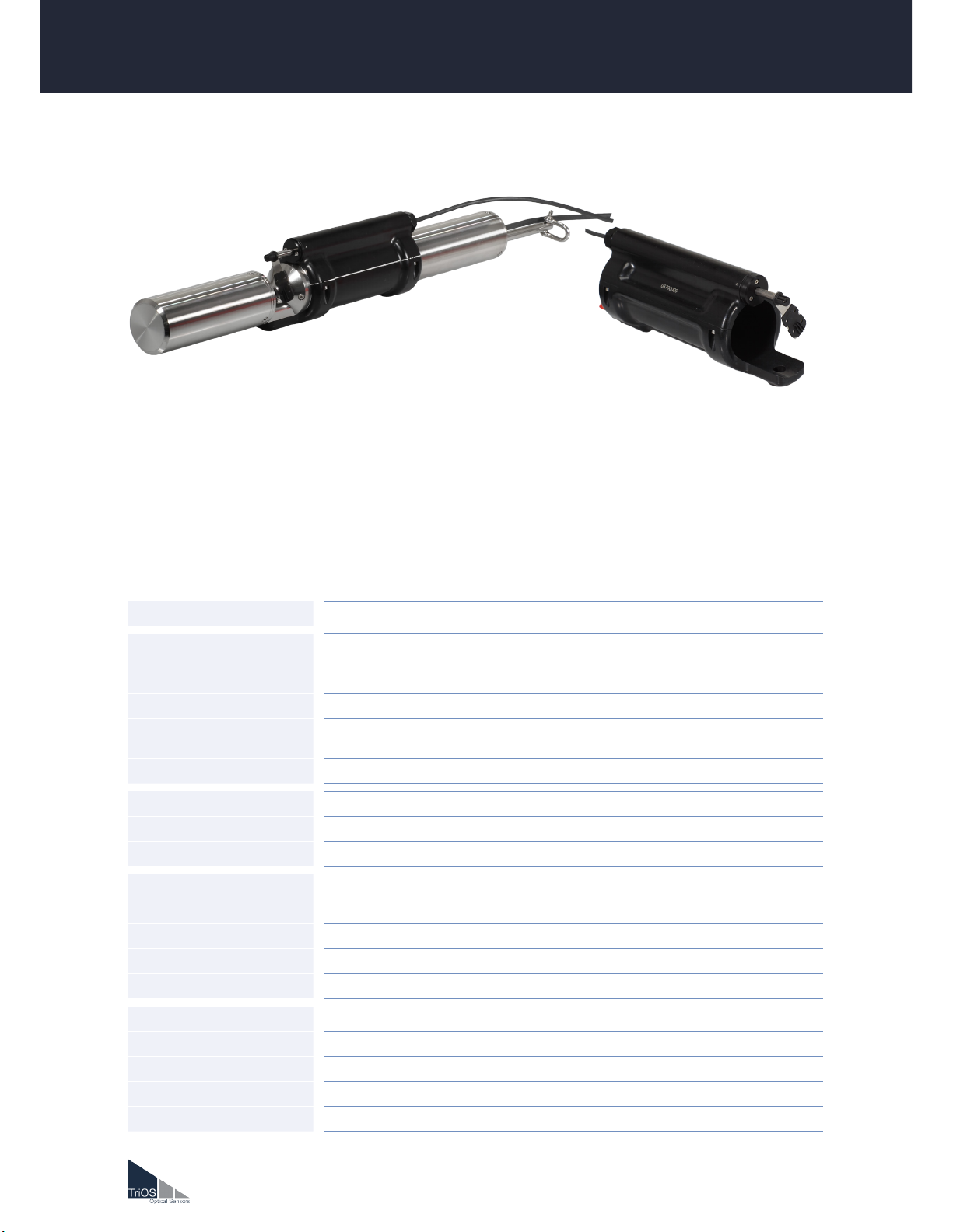
Wiper W55 V2
02A100XX8
Technical Specications
Path lengths 2 mm, 5 mm, 10 mm
Control port
4-pin M8-plug
A suitable M8 connection cable with open end is included in the scope of
delivery.
Trigger input 5-24 VDC (±10% )
Power consumption
trigger input 2...15 mA
Operating time (max.) 3 Seconds
Dimensions L x Ø 175 mm x 80 mm
Weight 0.52 kg
Material NBR, POM, TPE (PP, EPDM), Titanium or V4A
Power supply 12-24 VDC (± 10 %)
Power consumption approx. 2-6 W in operation; max. 0.75 W in standby
Maintenance eort ≤ 0.5 h/month typical
Maintenance interval depending on application
Warranty 1 year (EU & USA : 2 years)
Max. Pressure 1 bar
Protection Type IP68
Inow velocity up to 10 m/s
Operating temperature +2...+40 °C
Storage temperature -10 °C...+70 °C
The TriOS Wiper W55 V2 provides an additional cleaning option for all TriOS photometers with path lengths
up to 10 mm. The wiper housing can be mounted on the sensor in just a few steps and provides reliable
cleaning of the measurement windows. The new magnetic axis lock allows quick and easy wiper blade re-
placement, without any tools.
The new version of the wiper now features blockage detection and removal, and a service mode that increas-
es the life of the wiper through regular use. The accessory can also be used in seawater up to a depth of 10m.

2
D04-067en202111 Quick Guide Wiper W55 V2
TriOS Mess- und Datentechnik GmbH · Bürgermeister-Brötje-Str. 25 · D-26180 Rastede · Germany
fon: +49 (0) 4402 69670 - 0 · fax: +49 (0) 4402 69670 - 20 · [email protected] · www.trios.de
Wiper W55 V2 // Quick Guide
Quick Guide
1 Scope of Delivery
02A100008
1x Wiper
1x M8 open end cable
1x adjustment screw with o-ring
1x compressed air tting incl. sealing plug
1x magnet
02A100X18
5x wiper blades 2, 5 or 10 mm path
1x axis for 2, 5 or 10 mm path
1x grease
Optional (recommended)
1x protective cage
1x hexagonal oset screwdriver 5 mm
00P100010
The wiper blades and the axis are not included in the scope of delivery of the wiper housing, as these must
be selected depending on the path length of the sensor. A set of wiper blades contains ve wiper blades and
an axis of the appropriate size incl. grease.
Item number
02A100008 Wiper W55 V2
02A100218 Set with wiper blades for 2 mm path
02A100518 Set with wiper blades for 5 mm path
02A100618 Set with wiper blades for 10 mm path
2 Inserting / changing the wiper blade
If there are larger particles or objects in the sample water, you should always use
a protective cage to avoid damaging the wiper gear (see p. 9 for installation).
NOTICE
We recommend replacing the wiper blades every 4-5 weeks. The axis should be
changed every 5-6 months (new box).
NOTICE

3
D04-067en202111 Quick Guide Wiper W55 V2
TriOS Mess- und Datentechnik GmbH · Bürgermeister-Brötje-Str. 25 · D-26180 Rastede · Germany
fon: +49 (0) 4402 69670 - 0 · fax: +49 (0) 4402 69670 - 20 · [email protected] · www.trios.de
Wiper W55 V2 // Quick Guide
1. First place the wiper blade on the axis. To do this, push the wiper blade onto the axis until you hear a click.
2. Slightly grease the O-ring on the axis and insert the axis into the spring in the wiper housing. The axis
groove is magnetically tightened and must be inserted as far as it will go and, if necessary, turned slightly
until the correct position engages.
Wiper blades and axis must always be selected to match the path length of the
sensor, otherwise the measuring windows may be damaged.
NOTICE
The wiper axis is not seated correctly until the O-ring is no longer visible and the
axis can no longer rotate.
NOTICE
Never immerse the wiper in water without the axis installed! Since no other seal
is installed, unrepairable damage will occur which is not covered by the warranty.
NOTICE

4
D04-067en202111 Quick Guide Wiper W55 V2
TriOS Mess- und Datentechnik GmbH · Bürgermeister-Brötje-Str. 25 · D-26180 Rastede · Germany
fon: +49 (0) 4402 69670 - 0 · fax: +49 (0) 4402 69670 - 20 · [email protected] · www.trios.de
Wiper W55 V2 // Quick Guide
If the wiper gets stuck in the light path or is jammed by an object, we recommend removing the wiper com-
pletely from the sensor to prevent damage to the transmission. To do this, loosen the four screws on the wiper
housing and remove the wiper from the sensor.
Alternatively, only the axis can be pulled out. It is held magnetically and can simply be pulled out in the direc-
tion of the axis. Please remember to remove the wiper blade beforehand.
It is recommended to replace the O-ring and axis every 5-6 months.
1. Remove the axis with the wiper and the sealing ring.
2. Slightly grease the O-ring of the new axis and attach the new wiper blade.
3. Insert the new axis with wiper blade and O-ring into the spring in the wiper housing. The axis groove is
magnetically tightened and must be inserted as far as it will go and, if necessary, turned slightly until the
correct position engages.
3 Change housing seal (O-ring) and axis
4 Installation on the sensor
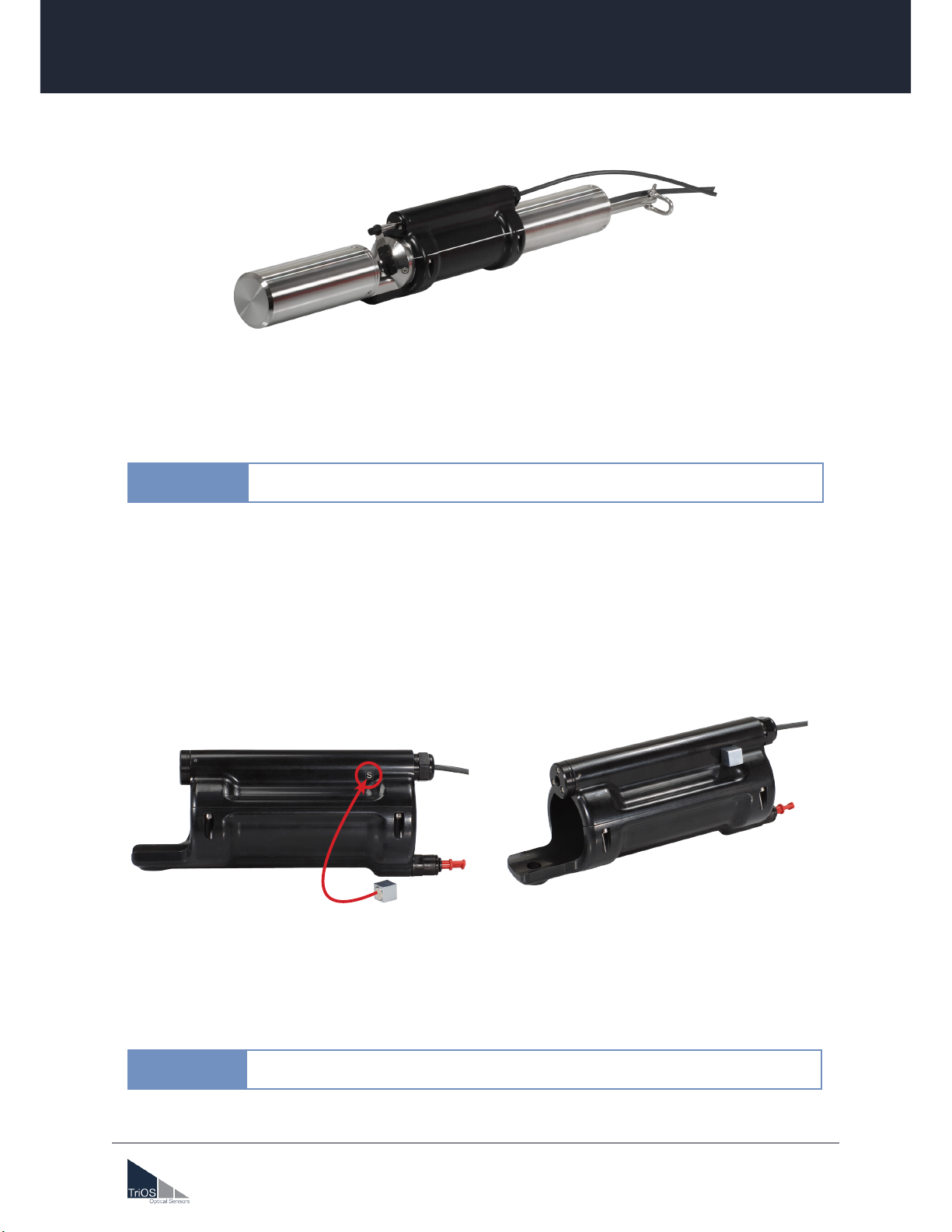
1. Place the lower housing of the wiper against the sensor and align it with the screw hole. Now tighten the
positioning screw.
positioning screw
lower housing
wiper housing
1.
2.
3. To change the wiper blade, it can be easily removed by lifting the upper part of the cover slightly and
pulling off the blade.
External mechanical loads, such as turning the wiper or the axis by hand, can
damage the gear unit!
NOTICE
Attention, the axis is held magnetically and must be pulled out in the direction of
the axis. Do not attempt to unscrew the axis under any circumstances.
Please make absolutely sure that there is an O-ring on the adjustment screw.
NOTICE
NOTICE
2. Place the upper part of the wiper housing on top and fasten with the four screws. At first only screw the
screws in very slightly and then tighten them one by one in a symmetrical order.
lower housing
wiper housing
positioning screw with o-ring
5
D04-067en202111 Quick Guide Wiper W55 V2
TriOS Mess- und Datentechnik GmbH · Bürgermeister-Brötje-Str. 25 · D-26180 Rastede · Germany
fon: +49 (0) 4402 69670 - 0 · fax: +49 (0) 4402 69670 - 20 · [email protected] · www.trios.de
Wiper W55 V2 // Quick Guide
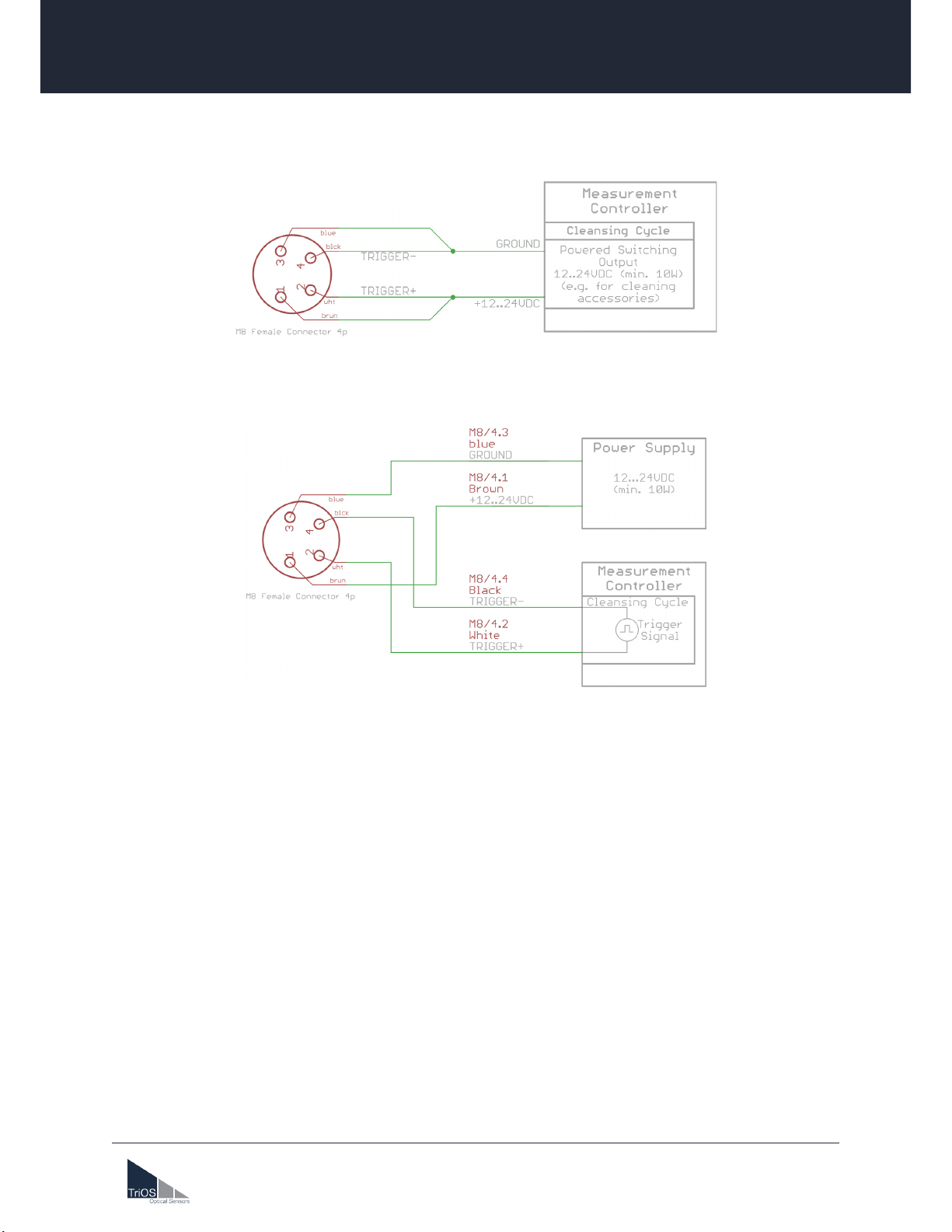
If the wiper is connected using the supplied M8 connection cable (see option 1), the cleaning process is au-
tomatically started after the supply voltage of 12 – 24 VDC has been applied. This lasts approx. 2-3 seconds
(two wiping cycles) – then the wiper stops in the parking position. For further wiping operations, the power
supply must be interrupted for at least one second and then reconnected.
IMPORTANT: The supply voltage must remain switched on until the end of the wiping process (reaching the
parking position), otherwise the wiper may stop at an undened point. In the worst case, it then covers the
light path and faulty measurements occur!
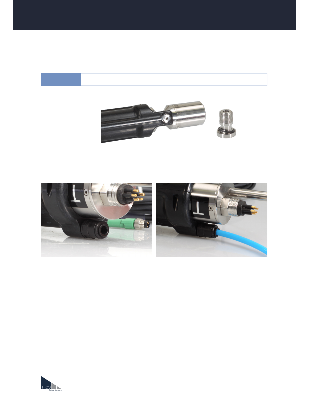
For an alternative connection where power supply and cleaning control (triggering) are separate, the open
end of the M8 line can be disconnected (see option 2). Remove the twin ferrules and equip the individual
cores with single ferrules. Now the wiper can be connected to a suitable DC voltage source according to the
connection diagram shown in the Option 2 gure. The trigger line in turn can be connected to a controller
which controls the cleaning cycle. The wiping process is started by a voltage signal (5 – 24 V; min. duration:
100 ms) on the trigger line. Here, too, two wiping cycles are carried out, which require approx. 2-3 seconds.
A new wiping process can then be started by re-triggering (pause between the intervals ≥ 1 second).
IMPORTANT: Even with this circuit option, it must be ensured that the supply voltage remains switched on
during the wiping process!
Option 1: M8 connection cable with open end, trigger is connected parallel to the supply voltage (included in
delivery).
Option 2: M8 connection cable with open end, trigger and power supply are separate.
5 Commissioning
6
D04-067en202111 Quick Guide Wiper W55 V2
TriOS Mess- und Datentechnik GmbH · Bürgermeister-Brötje-Str. 25 · D-26180 Rastede · Germany
fon: +49 (0) 4402 69670 - 0 · fax: +49 (0) 4402 69670 - 20 · [email protected] · www.trios.de
Wiper W55 V2 // Quick Guide
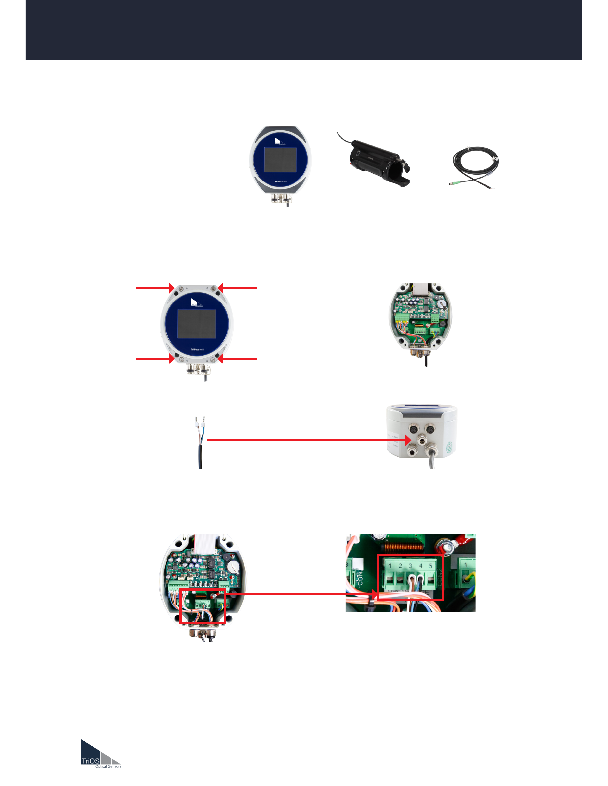
6 Connecting the wiper to the TriBox mini
Necessary components
TriBox mini Wiper Open End Cable
Connection
1. Open the lid of the TriBox mini by removing the dark grey covers and unscrewing the four screws under-
neath.
2. Place the wiper cable through the cable guide of the TriBox mini and tighten the cable guide.
3. Connect the blue-black wire of the wiper cable to the CON2 connector, pin 4 (VOUT-) and the brown-
white wire to the CON2 connector, pin 3 (VOUT+). Make sure that the screws are tightened.
4. Close the TriBox mini lid, tighten the four screws and place the grey covers on the TriBox mini.
5. The wiper settings can now be adjusted in the TriBox mini menu under “Measurement & Cleaning”. Un-
der “Cleaning Settings”, the cleaning duration should be at least 10 seconds and set to “active”.
7
D04-067en202111 Quick Guide Wiper W55 V2
TriOS Mess- und Datentechnik GmbH · Bürgermeister-Brötje-Str. 25 · D-26180 Rastede · Germany
fon: +49 (0) 4402 69670 - 0 · fax: +49 (0) 4402 69670 - 20 · [email protected] · www.trios.de
Wiper W55 V2 // Quick Guide
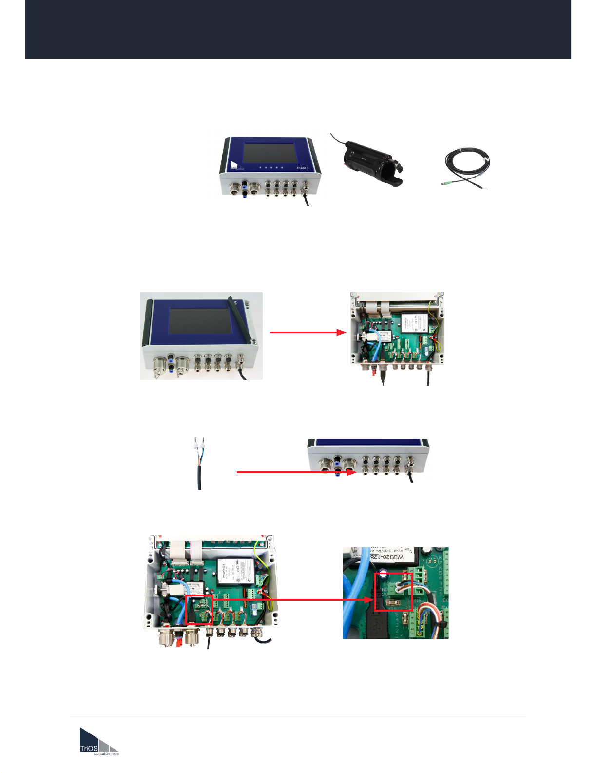
7 Connecting the wiper to the TriBox 3
Necessary components
Connection
1. Open the lid of the TriBox3 by removing the dark grey covers and unscrewing the screws underneath.
TriBox3 Wiper Open End Cable
2. Place the wiper cable through the TriBox3 cable guide and tighten the cable guide on the wider part of
the cable.
3. Connect the blue-black wire of the wiper cable to the CON15 connector, pin 2 and the brown-white wire
to the CON15 connector, pin 1. Make sure the screws are tightened.
4. Close the TriBox3 lid, tighten the screws and place the grey covers on the TriBox3.
5. The wiper settings can now be adjusted in the TriBox3 menu under “Cleaning”. Cleaning time should be
at least 10 seconds and the valve must be activated.
8
D04-067en202111 Quick Guide Wiper W55 V2
TriOS Mess- und Datentechnik GmbH · Bürgermeister-Brötje-Str. 25 · D-26180 Rastede · Germany
fon: +49 (0) 4402 69670 - 0 · fax: +49 (0) 4402 69670 - 20 · [email protected] · www.trios.de
Wiper W55 V2 // Quick Guide
8 Blocking detection
After three wiping processes, the wiper blade always returns to the starting position. At the beginning of
each process, the position is briey checked. If the optical path is blocked, this is detected by the wiper and
it attempts to loosen the interfering component with very short wiping movements. If this is unsuccessful, the
wiper blade can also be removed when dry and the axle can be pulled out individually to manually unblock it.
The service mode is the new feature of the W55 V2 wiper. The service mode is activated by the supplied
magnet and ve full rotations in both directions are performed. This adjusts the home position and lubricates
the planetary gear in all directions. It is recommended to remove the upper wiper housing from the sensor rst
before activating the service mode to avoid damage to the measuring windows and to ensure free rotation.
To increase the life of the wiper, it is recommended to perform this function 1x per month.
To activate the service mode, hold the supplied magnet against the housing in the area of the „S“ mark. Move
the magnet slightly around the mark to hit the activation point. Once Service Mode is activated, the axis with
the wiper blade will begin full rotations.
The Service Mode should never be activated with the wiper protection cage
mounted, otherwise damage to the wiper will occur.
NOTICE
Attention, the axis is held magnetically and must be pulled out in the direction of
the axis. Do not attempt to unscrew the axis under any circumstances!
NOTICE
9 Service Mode

9
D04-067en202111 Quick Guide Wiper W55 V2
TriOS Mess- und Datentechnik GmbH · Bürgermeister-Brötje-Str. 25 · D-26180 Rastede · Germany
fon: +49 (0) 4402 69670 - 0 · fax: +49 (0) 4402 69670 - 20 · [email protected] · www.trios.de
Wiper W55 V2 // Quick Guide
Wiper protective cage
00P100010
Size L x Ø 220 mm x 88 mm
Weight ~ 0.5 kg
Material POM
Technical Specications
The sturdy plastic (POM) protective cage has been designed to keep coarse dirt and larger objects away
from the wiper, thus protecting it from damage. However, the recesses allow the measuring medium to reach
the optical path of the sensor unhindered. The measured values are therefore not inuenced by unwanted
contamination.

10
D04-067en202111 Quick Guide Wiper W55 V2
TriOS Mess- und Datentechnik GmbH · Bürgermeister-Brötje-Str. 25 · D-26180 Rastede · Germany
fon: +49 (0) 4402 69670 - 0 · fax: +49 (0) 4402 69670 - 20 · [email protected] · www.trios.de
Wiper W55 V2 // Quick Guide
8 Installation of the protective cage on the sensor
1. The wiper must be correctly installed before mounting the cage on the sensor (see page 2 to 4).
2. Push the protective cage with the opening in the direction of the wiper and align it with the wiper shaft.
The sensor must be inserted in the middle of the holder provided inside the protective cage.
3. If the protective cage is correctly fitted, it must be finally fixed to the sensor with an Allen key (5 mm).
11
D04-067en202111 Quick Guide Wiper W55 V2
TriOS Mess- und Datentechnik GmbH · Bürgermeister-Brötje-Str. 25 · D-26180 Rastede · Germany
fon: +49 (0) 4402 69670 - 0 · fax: +49 (0) 4402 69670 - 20 · [email protected] · www.trios.de
Wiper W55 V2 // Quick Guide
9 Mounting the compressed air purge on the wiper
1. The adjustment screw needs to be fixed to the lower housing for mounting the compressed air purge.
Spare part no.: 10P000000
2. Moreover, the compressed air fitting needs to be inserted into the rear housing to connect a compressed
air tube.
3. The compressed air purge system is now operational and the compressed air is lead to the optical path
via the wiper.
Please make absolutely sure that there is an O-ring on the adjustment screw.
NOTICE
This manual suits for next models
1
Table of contents
Popular Ultrasonic Jewelry Cleaner manuals by other brands

IPC Gansow
IPC Gansow TITAN 151BF 87 Translation of the original operating instructions

Silvercrest
Silvercrest 390783 2201 operating instructions

Prochem
Prochem PEAK operating instructions

eta
eta Finestro Instructions for use

Kärcher
Kärcher hds 895 operating instructions

James products
James products SONIC 3D user guide


Duraline Systems
Duraline Systems DURAsonic XPD-Series user manual

BGS technic
BGS technic 6880 instruction manual

Carrera
Carrera Sinus Ultra Instructions for use and guarantee

Makita
Makita CL107FDZ instruction manual

GemOro
GemOro SPARKLE SPA PRO Instructions for use

Vessel
Vessel IPC20-E instruction manual