Triple Play Communications ASE-1019 User manual
Triple Play Communications Document 3013800-701
250 East Drive, Suite F Rev 1.1
Melbourne, FL 32904 July 2015
1
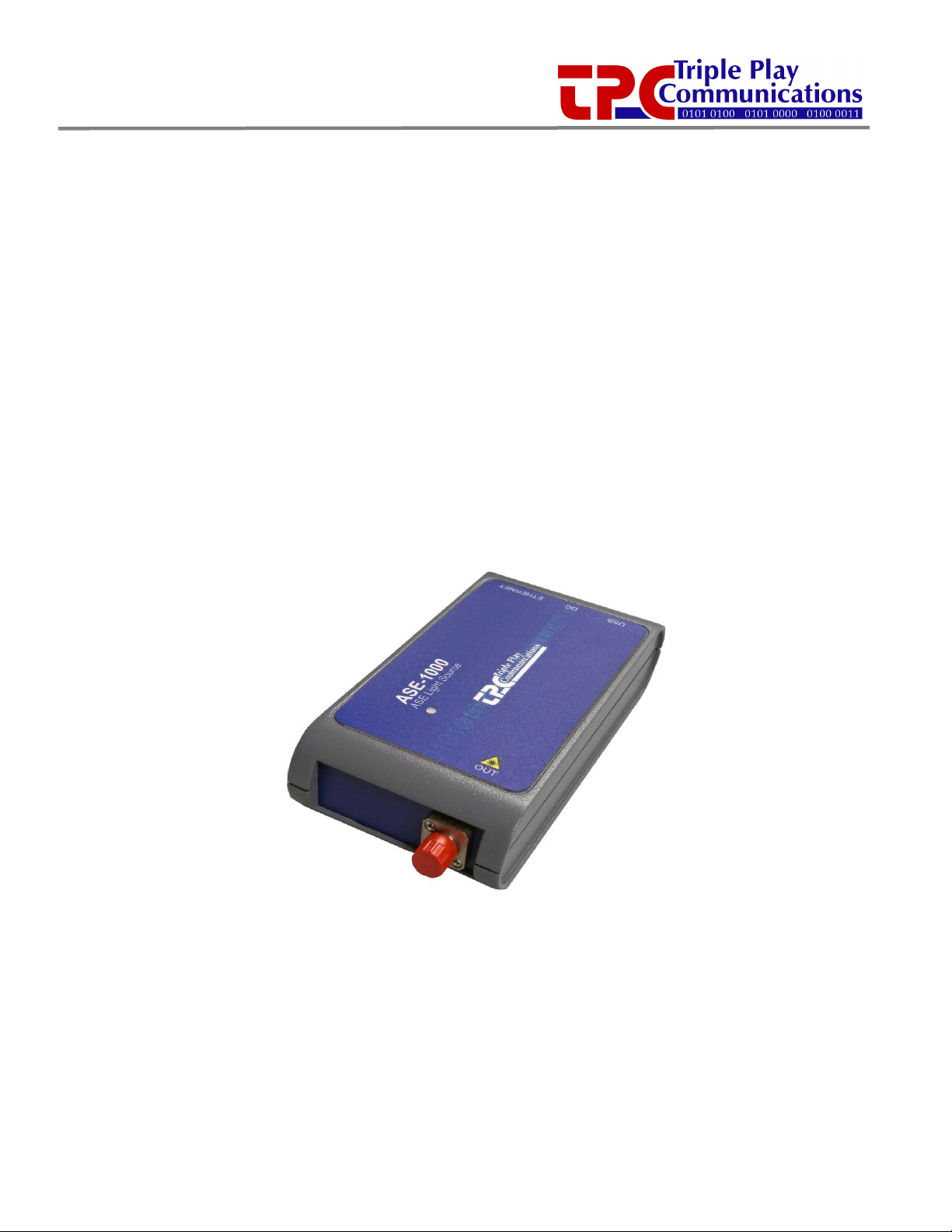
ASE-1019
ASE Light Source
ASE-1019 ASE Light Source
User’s Manual

2
Revision History
Document
Revision
Date
Description
1.0
Feb 2015
Initial Release
1.1
July 2015
Updated several GUI images of optical control/status

3
Table of Contents
Revision History ............................................................................................................................................2
1.0 Scope .................................................................................................................................................6
2.0 Operational Overview......................................................................................................................6
2.1 Default Operational Settings and Non-Volatile Memory .........................................................7
3.0 Description of All Items Included in ASE-1019 Packaging ...........................................................7
4.0 Optical Safety....................................................................................................................................8
4.1 National Standards.......................................................................................................................8
4.2 Class 1M Source of Optical Radiation .........................................................................................8
4.3 Connecting Optical Cables..........................................................................................................9
4.4 Eye Protection...............................................................................................................................9
5.0 USB GUI Software Installation and Initial Power-On .....................................................................9
5.1 USB GUI Installation .....................................................................................................................9
5.2 USB Connection to ASE-1019 Module and Initial Power-On..................................................11
6.0 Ethernet Based Control/Status Setup and Initial Power-On.......................................................12
6.1 Initial Setup for Ethernet Control/Status..................................................................................12
6.2 IP Address Reset Button (on bottom side of module) ............................................................14
7.0 USB GUI Operation .........................................................................................................................15
7.1 Getting Started with the USB GUI .............................................................................................15
7.2 Main Menu Control and Status Functions ...............................................................................15
7.2.1 Primary Status Display ..........................................................................................................15
7.2.2 Primary Control Functions....................................................................................................16
8.0 Ethernet Browser GUI Operation ..................................................................................................18
8.1 Optical Control/Status ...............................................................................................................18
8.1.1 Display of Status Parameters................................................................................................18
8.2 System Status..............................................................................................................................22
8.3 Ethernet Setup............................................................................................................................23
8.4 Revision/Update .........................................................................................................................24
9.0 Optical and Electrical Specifications.............................................................................................26
10.0 Mechanical Dimensions.................................................................................................................27
11.0 Part Numbers for Ordering............................................................................................................28

4
List of Figures
Figure 2.0-1 - ASE-1019 Functional Block Diagram and Internal Connectivity ......................................6
Figure 3.0-1 - ASE-1019 Packaging Box......................................................................................................7
Figure 3.0-2 - ESD Container with ASE-1019 Inside...................................................................................8
Figure 3.0-3 - AC/DC Plug Adapter, Ethernet Cable, USB Cable, and CD-ROM with USB GUI and
User’s Manual................................................................................................................................................8
Figure 4.2-1 -ASE-1019 Laser Radiation Safety Label for Class 1M Laser Product ................................9
Figure 5.1-1 - ASE-1019 USB GUI Installation Folder Contents on CD-ROM .........................................10
Figure 5.1-2 - Windows User Account Control Notification ...................................................................10
Figure 5.1-3 - USB GUI Installation Progress Window .............................................................................10
Figure 5.1-4 - USB GUI Installation Complete Window ...........................................................................11
Figure 5.2-1 - Example of ASE-1019 USB GUI Main Menu.......................................................................11
Figure 5.2-2 - Error Message Displayed When ASE-1019 is Not Connected to USB Port.....................12
Figure 6.0-1 - Two Methods of Using an Ethernet Interface to the ASE-1019 Module ........................12
Figure 6.2-1 - ASE-1019 IP Address Reset Button Location ....................................................................14
Figure 7.1-1 - How to Move and Close the Main Menu Window, Open Device Info Window ............15
Figure 7.2.1-1 - Critical Status Area of the Main Menu, in both dBm and Watts ..................................16
Figure 7.2.2-1 - Key Control Functions on the Main Menu .....................................................................16
Figure 7.2.2-2 -ACC Mode with a User Entered Setting of 475 mA for the Bias Current....................17
Figure 7.2.2-3 -APC Mode with a User Entered Setting of +18.0 dBm for the Output Power ...........17
Figure 8.1.1-1 - Type Appropriate IP Address of Module to Access Home Page..................................18
Figure 8.1.1-2 - Optical Control and Status Page.....................................................................................19
Figure 8.1.1-3 – User Selects Watts to be Used for Displaying Output Power......................................20
Figure 8.1.1-4 -ACC Mode with a User Entered Setting of 475 mA for the Bias Current....................20
Figure 8.1.1-5 -APC Mode with a User Entered Setting of +18.0 dBm for the Output Power ...........21
Figure 8.1.1-6 - Amplifier Output Disabled by the User.........................................................................21
Figure 8.1.1-7 -Continuous Update Box Should Remain Checked Under Most Conditions..............22
Figure 8.2-1 - System Status Information.................................................................................................22
Figure 8.2-2 -Click to Reset the Automatic Laser Shutdown Condition ..............................................23
Figure 8.3-1 - Ethernet Setup Controls with Factory Default IP Address ..............................................23
Figure 8.4-1 - Firmware Revision/Update Page, Browse to a File and Click Update to Begin
Downloading New Firmware ....................................................................................................................24
Figure 10.0-1 - ASE-1019 Module Mechanical Dimensions ....................................................................27

5
List of Tables
Table 2.1-1 -Default Operational Settings as Shipped from the Factory...............................................7
Table 5.1-1 - Step-by-Step Instructions to Install the USB GUI...............................................................10
Table 6.1-1 - Ethernet Port Setup for Standalone Computer Operation with ASE-1019 .....................13
Table 6.1-2 - ASE-1019 Ethernet Port Setup for Operation with Ethernet Router Using Static IP......13
Table 6.1-3 - ASE-1019 Ethernet Port Setup for Operation with Ethernet Router Using Dynamic IP14
Table 8.3-1 - Ethernet Configuration Description of Parameters...........................................................24
Table 9.0-1 – ASE Light Source Specifications .........................................................................................26
Table 9.0-2 – Typical Output Spectrum at 25°C Over Entire Wavelength Range .................................26
Table 9.0-3 - Optical Power Meter Specifications....................................................................................27
Table 9.0-4 - Electrical, Mechanical, and Environmental Specifications................................................27

6
1.0 Scope
This ASE-1019 User’s Manual gives an overview of the hardware and software design and describes
module installation, configuration, alarms, and operator control and status capability.
2.0 Operational Overview
The ASE-1019 is an ASE light source providing a typical output power of +19 dBm. It is one of the
series of amplifier/light source modules which are designed as user-friendly, compact, portable,
cost-effective solutions for use in a variety of applications. A detailed block diagram showing the
internal hardware connectivity of this chassis is shown in Figure 2.0-1.
An Ethernet communications hardware interface is provided to allow the ASE-1019 to be
controlled via a 10/100BaseT link using either Static or Dynamic IP addressing. In this
configuration, a standard HTML browser (e.g. Firefox, Chrome, Internet Explorer) provides the user
interface and the various control and status HTML pages are integrated into the microcontroller’s
firmware. A +5V AC/DC adapter is provided to power the module.
In addition to the Ethernet GUI, the ASE-1019 can be connected directly to a Windows based
computer which runs the USB graphical user interface (GUI) software. This GUI also provides
complete control and status of all amplifier and optical power monitoring functions.
The output optical power level is measured using a 1% tap to minimize insertion loss. An onboard
temperature sensor allows the power monitoring circuitry to be calibrated during production test
to provide measurement resolution of 0.01 dB and linearity (relative accuracy) of 0.1 dB over an
operating temperature range of 0°C to 40°C.
A/D
Converter
Microcontroller
+5V
+3.3V
USB
Bridge USB Comm
+5V DC from
wall adapter
Temperature
Sensor
Optical
Tx
1% Optical
Tap
Optical
Power
Monitor
Power
Filtering and
Conversion
Ethernet
Comm
Ethernet
Controller
Optical
Tx
Optical ASE
Light Source
+5V DC from
USB port
Diode OR
Figure 2.0-1 - ASE-1019 Functional Block Diagram and Internal Connectivity
The GUI application has an additional optional feature which allows the user to perform time
stamped data logging. This option includes capturing the input and output optical power levels as
7
well as the corresponding amplifier bias current, operating modes, temperature, LOS level and
alarms, and writing this information to a .csv file.
2.1
Default Operational Settings and Non-Volatile Memory
The ASE-1019 module always saves the last operational state in non-volatile memory regardless of
whether the USB GUI or the Ethernet interface is used for control and status. All changes to any
control parameters are automatically saved in non-volatile memory and recalled whenever the
module is powered on.
The ASE-1019 module is shipped from the factory with the default settings given in Table 2.1-1.
This module is setup to be “ready for operation” as soon as it is powered on with the bias current
set to achieve the advertised output power so the module can be placed directly into service
without changing any parameters if desired.
Table 2.1-1 - Default Operational Settings as Shipped from the Factory
Control Function
Default Setting
Description
Bias Current ~ 450 mA
Set for advertised output power
(+19 dBm), so slightly different for
every amplifier
Output Power +19 dBm
Set for advertised output power,
used when set to APC mode
Auto Control Mode
Auto Current Control
Automatic current control mode
Amplifier Output
Enabled
Amplifier output is enabled
Optical Power Display
dBm
Power is displayed in dBm
Ethernet Mode
Static
Static IP address mode
IP Address
192.168.1.234
Default IP address
IP Subnet
255.255.255.0
Default IP subnet
IP Gateway
192.168.1.1
Default IP gateway
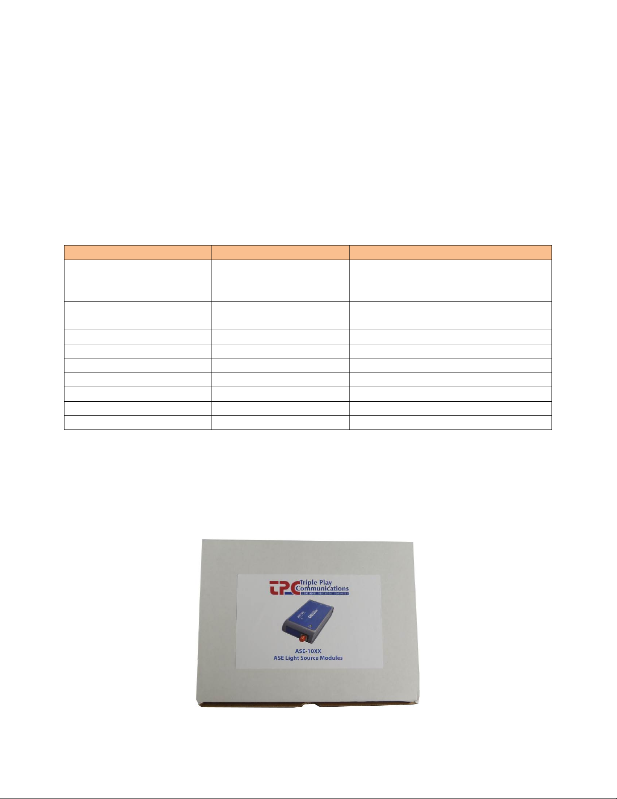
3.0 Description of All Items Included in ASE-1019 Packaging
The photos below show all the items which are included with the ASE-1019. There is an Ethernet
cable, a USB cable, and an AC/DC power adapter along with a CD-ROM containing the USB GUI
installation files and user’s manual.
Figure 3.0-1 - ASE-1019 Packaging Box

8
Figure 3.0-2 - ESD Container with ASE-1019 Inside
Figure 3.0-3 - AC/DC Plug Adapter, Ethernet Cable, USB Cable, and CD-ROM with USB GUI and
User’s Manual
4.0 Optical Safety
4.1
National Standards
United States Government safety requirements for lasers and laser amplifiers are described in the
DHHS/CDRH radiation performance standards, 21 CFR 1040.10 and 1040.11. International safety
standards for lasers and laser amplifiers are described in the IEC-60825-1:2007 document.
4.2
Class 1M Source of Optical Radiation
The ASE-1019 delivers invisible laser radiation with fiber-coupled output power of up to 135 mW
(21.3 dBm) and as such are Class 1M sources of optical radiation. This module includes the warning
information as shown in Figure 4.2-1 as part of its label to make it easily identifiable as a Class 1M
source. Internally, the module contains one 980-nm laser-diode pump.

9
CAUTION
INVISIBLE LASER RADIATION
Do not view directly with optical instruments
CLASS 1M LASER PRODUCT
P
out
max: 135 mW 1520 –1620 nm
Figure 4.2-1 - ASE-1019 Laser Radiation Safety Label for Class 1M Laser Product
ASE-1019 Safety Specifications:
1) Wavelength range: 1520 to 1620nm (invisible, infrared region).
2) Beam size: The beam is normally safely confined within a single-mode optical fiber with a
mode-field diameter of about 10-um.
3) Beam divergence: If the beam is allowed to escape into free space (e.g. by not connecting an
optical cable to the input or output connectors, with the dust caps removed), the beam
divergence is given by the numerical aperture of the optical fiber, typically 120mrad (half
angle).
4) Maximum power: The maximum output power (in the form of amplified spontaneous
emission (ASE)) of this module, in the absence of an optical input, is less than the Class 1M
limit of 135 mW (21.3 dBm). This power can be emitted from the output connector (ASE
power emitted from the input connector does not exceed Class 1 limits.). With a saturating
input signal of 0 dBm (1mW), the maximum output power of the module is also less than
135 mw (21.3 dBm).
4.3
Connecting Optical Cables
Optical connections to the module are made via FC connectors. The supplied dust caps should
always be left on the connectors when not in use. These dust caps not only keep the connectors
clean, but they also protect the user from any optical radiation that may emanate from these
connectors.
4.4
Eye Protection
Under normal operating conditions, with an optical cable connected to the output, or with the
dust caps on both FC connectors, there is no optical radiation emitted into free space. Therefore,
no special eye protection is required. It is recommended that optical connection or disconnection
to the module be carried out only with the optical output disabled using the GUI.
5.0 USB GUI Software Installation and Initial Power-On
This paragraph describes the USB GUI installation and power-on procedure so if only the Ethernet
interface is planned to be used, please skip to paragraph 6.0.
5.1
USB GUI Installation
Before initially powering on the ASE-1019 module, the USB GUI should be installed onto a
Windows 7, XP, or 8 computer. The included CD-ROM contains all of the required installation files.
Proceed to install the USB GUI by following the instructions in Table 5.1-1. Several screen captures
of the installation process are shown in the figures below.
The installation procedure will install the ASE-1019 GUI application program as well as the National
Instruments Run Time Engine and all USB drivers needed to communicate with the ASE-1019
module. Therefore, no additional driver or software installation is necessary.

10
Table 5.1-1 - Step-by-Step Instructions to Install the USB GUI
Step #
Description
1
Insert the disk into the Windows computer’s DVD drive, navigate into the USB GUI
folder and verify the file structure of the CD-ROM looks as shown in Figure 4.1-1.
2
Double click on the Install_ASE10XX GUI file and the Windows User Account
Control message shown in Figure 4.1-2 will appear. Click Yes to continue to install
the software.
3
While the installation is in progress for approximately 4 minutes, the small window
shown in Figure 4.1-3 will appear to indicate the installation process is in progress.
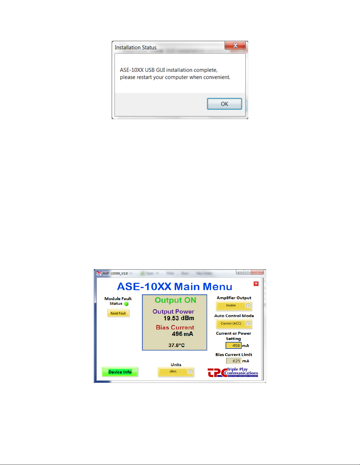
4
Once installation is complete, the window in Figure 4.1-4 will be shown to remind
the user to restart the computer at the earliest convenience. The user can click OK to
continue, the computer will not restart until the user specifically commands a
Windows restart.
5
Whenever convenient, restart the computer.
6
Proceed to paragraph 5.2 of this document to continue the setup procedure.
Figure 5.1-1 - ASE-1019 USB GUI Installation Folder Contents on CD-ROM
Figure 5.1-2 - Windows User Account Control Notification
Figure 5.1-3 - USB GUI Installation Progress Window
11
Figure 5.1-4 - USB GUI Installation Complete Window
5.2
USB Connection to ASE-1019 Module and Initial Power-On
Provide power to the module by plugging the +5V AC/DC adapter into a standard 120 VAC wall
outlet then into the module’s DC port. The LED on the top side of the module should illuminate to
a green color indicating that DC power is being supplied to the module. If the LED does not
illuminate, it is an indication that DC power is not being supplied to the module. Plug the included
USB cable into the computer and into the ASE-1019 module’s USB port.After a few seconds, the
computer should indicate it recognizes the module with the typical Windows USB connection
sound.
Open the GUI application by clicking on the Windows Start icon, All Programs, TPC folder, and
finally the ASE_10XX application. The GUI will open and the main menu window will display and
look similar to that shown in Figure 5.2-1. At this point the module is ready to be controlled and
the ASE light source output signal is available at the optical FC connector labeled “OUT”. Please go
to paragraph 7.0 in order to obtain more details regarding specific operation of the USB GUI
application.
Figure 5.2-1 - Example of ASE-1019 USB GUI Main Menu
If the GUI application is opened when no ASE-1019 module is connected to the USB port, the error
message shown in Figure 5.2-2 will appear. In this case, close the GUI, connect an ASE-1019 to the
USB port, then re-open the GUI application.

12
Figure 5.2-2 - Error Message Displayed When ASE-1019 is Not Connected to USB Port
6.0 Ethernet Based Control/Status Setup and Initial Power-On
An external computer with a 10/100BaseT Ethernet port is required to provide control and status
for the ASE-1019 module using a standard HTML browser (Chrome, Firefox, Internet Explorer)
based GUI. When using Ethernet communications to control/status the ASE-1019 module, there is
no other special software required, the browser (Chrome, Firefox, Internet Explorer) is sufficient.
There are two primary ways to configure the hardware connection between the external computer
and the ASE-1019 module, both are shown in Figure 6.0-1. Use the included Ethernet cable and
setup the hardware connection in either of the two ways shown in the figure.
10/100BaseT
Ethernet Cable
10/100BaseT
Ethernet Cable
10/100BaseT
Ethernet Cable
External
Computer
with Browser
ASE-1019
Module
OR
(direct connection)
External
Computer
with Browser
Ethernet
Router
ASE-1019
Module
Figure 6.0-1 - Two Methods of Using an Ethernet Interface to the ASE-1019 Module
Provide power to the module by plugging the +5V AC/DC adapter into a standard 120 VAC wall
outlet then into the module’s DC port. The LED on the top side of the module should illuminate to
a green color indicating that DC power is being supplied to the module. If the LED does not
illuminate, it is an indication that DC power is not being supplied to the module.
6.1
Initial Setup for Ethernet Control/Status
The ASE-1019 module is shipped in Static IP address mode to allow communication via a direct
connection to a standalone computer as shown in the upper block diagram of Figure 6.0-1. In
order to initially communicate with the ASE-1019, setup the Ethernet port of the standalone
computer as given in Table 6.1-1.

13
Table 6.1-1 - Ethernet Port Setup for Standalone Computer Operation with ASE-1019
#
Description
1
Set up the properties of your computer’s LAN Ethernet connection by navigating as
follows:
- Select Start, Control Panel, Network and Internet, Network and Sharing Center,
then click on Change adapter settings on the left side
- Right click on your Local Area Connection and select Properties
- Click on Internet Protocol Version 4 (TCP/IPv4) and select Properties
- Click on Use the following IP address: type IP address 192.168.1.235, Subnet
Mask 255.255.255.0, Default Gateway (leave blank)
- Click on Use the following DNS server addresses: Preferred DNS Server (leave
blank), Alternate DNS server (leave blank)
- Click OK to exit all the windows
2
Connect the Ethernet cable from your computer directly to the module
3
Open a Chrome, Firefox, or Internet Explorer browser window
4
In the browser’s URL window, type 192.168.1.234 and wait for the ASE-1019 main screen
to appear.
5
Click on the menu for Optical Control/Status
If desired, the ASE-1019 can be fully controlled using only a standalone computer and its HTML
browser. If that is the desired method of control, please proceed to paragraph 8.0 which describes
the various screens, control, and status capable of being implemented with the HTML browser.
In order to connect the ASE-1019 module to an Ethernet router for remote control and status,
setup the module as described in Table 6.1-2 if a Static IP address is desired, or as described in
Table 6.1-3 if a Dynamic IP address is desired.
Table 6.1-2 - ASE-1019 Ethernet Port Setup for Operation with Ethernet Router
Using Static IP
#
Description
1
Click on Ethernet Setup at the top menu bar.
2
Select Static for the Ethernet Mode drop down menu.
3
Type in the new, desired IP Address, IP Subnet, and IP Gateway settings which are to be
used with your Ethernet Router.
4
Once all the desired settings are correct, click Apply Settings. Please note that once
Apply Settings is clicked, you will no longer be able to communicate with the module until
it is connected to the Ethernet Router on which the new settings are appropriate. If there
are ever problems accessing the module, the ASE-1019 can always be placed back into its
factory default state for the Ethernet Settings using the IP Address Reset button on the
bottom side of the module. See paragraph 6.2 for more details.
5
Connect the Ethernet cable from the Ethernet Router directly to the ASE-1019 module.
6
Using a computer which can also access this Ethernet Router, open a Chrome, Firefox, or
Internet Explorer browser window.
7 In the browser’s URL window, type the newly entered Static IP address of the module and
wait for the ASE-1019 main screen to appear.
8
Proceed to paragraph 8.0 which describes the various screens, control, and status capable
of being implemented with the HTML browser.
14
Table 6.1-3 - ASE-1019 Ethernet Port Setup for Operation with Ethernet Router Using
Dynamic IP
#
Description
1
Click on Ethernet Setup at the top menu bar.
2
Select DHCP for the Ethernet Mode drop down menu. It is not necessary to change the
IP Address, IP Subnet, and IP Gateway settings.
3
Click Apply Settings. Please note that once Apply Settings is clicked, you will no longer
be able to communicate with the module until it is connected to the Ethernet Router
setup for Dynamic IP addressing. If there are ever problems accessing the module, the
ASE-1019 can always be placed back into its factory default state for the Ethernet Settings
using the IP Address Reset button on the bottom side of the module. See paragraph 6.2
for more details.
4
Connect the Ethernet cable from the Ethernet Router directly to the ASE-1019 module.
5 There are two ways in which to determine the dynamic IP address once it has been
assigned to the module. The first is to use the Admin function of the Ethernet Router and
determine the Dynamic IP address which has been assigned to the ASE-1019 module. The
second is to connect to the USB port of the module and open the USB GUI. Click on the
Device Info box and the Device Information window will display the current IP address.
6 Using a computer which can also access this Ethernet Router, open a Chrome, Firefox, or
Internet Explorer browser window.
7
In the browser’s URL window, type the newly found Dynamic IP address of the module
and wait for the ASE-1019 main screen to appear.
8
Proceed to paragraph 8.0 which describes the various screens, control, and status capable
of being implemented with the HTML browser.
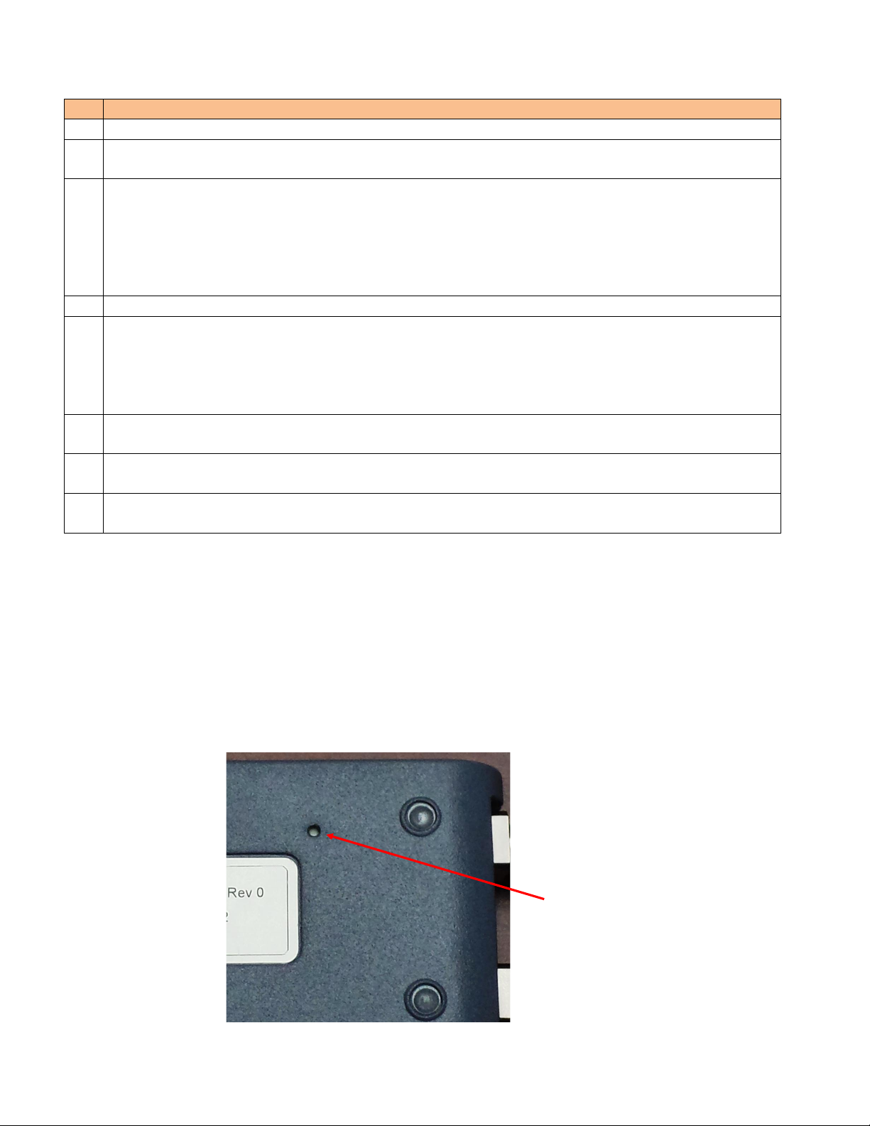
6.2
IP Address Reset Button (on bottom side of module)
The IP address reset button is located on the bottom side of the module, see Figure 6.2-1, and is
recessed so it is not possible to inadvertently reset the IP address. The tip of an ordinary ball point
pen can be used to press this reset button. Pressing and holding the IP Address Reset button for at
least 1 second reconfigures the 10/100BaseT Ethernet port to its default state which is: Static IP
address mode, IP address = 192.168.1.234, Subnet mask = 255.255.255.0, Default gateway =
192.168.1.254. During the execution of this command, the optical communications link is not
interrupted.
IP Address
Reset Button
Figure 6.2-1 - ASE-1019 IP Address Reset Button Location

15
7.0 USB GUI Operation
7.1
Getting Started with the USB GUI
Once the USB GUI application has been started using the steps described previously in paragraph
5.2, the ASE-1019 Main Menu will appear. This window remains visible until the application is
closed by clicking the “X” inside the red box in the upper right area of the Main Menu or by
removing the USB cable from the ASE-1019 module. This GUI application can only be active and
running when an ASE-1019 is physically connected to the computer using a USB cable. Otherwise,
the application will automatically close if no module connection is detected.
The Main Menu window can be moved and repositioned on the screen by clicking the bar at the
top of the window and dragging it to a different location. The size of this window cannot be
changed.
By clicking on Device Info, a new window is opened to show specific module information such as
the model number, part number, serial number, firmware and GUI revisions. This window cannot
be repositioned and is closed by clicking the red box in the upper right corner.
Figure 7.1-1 shows an example Main Menu window with several key areas highlighted.
Click and drag to reposition Click to close window
Click to open Device Information Menu
Figure 7.1-1 - How to Move and Close the Main Menu Window, Open Device Info Window
7.2
Main Menu Control and Status Functions
7.2.1 Primary Status Display
All of the critical status information from the ASE-1019 module is shown in the central area of the
Main Menu as highlighted in Figure 7.2.1-1.
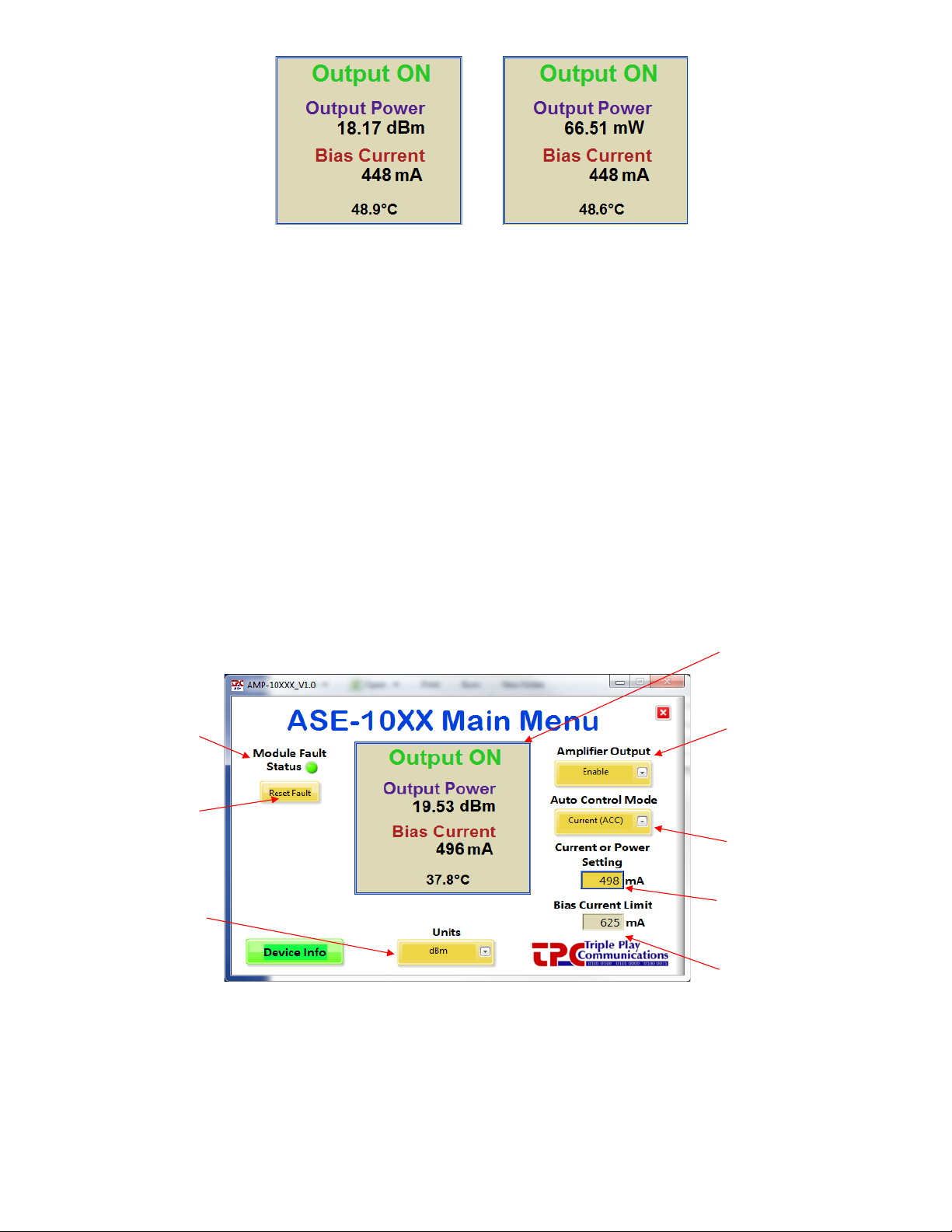
16
Figure 7.2.1-1 - Critical Status Area of the Main Menu, in both dBm and Watts
The key ASE-1019 module parameters of output status, output power, bias current, and
temperature are obtained from the module (by the external computer) and displayed in
prominently in this central area of the window.
The optical output power is monitored using a 1% tap to minimize insertion loss. The calculated
value is displayed in its designated location and can be shown in either dBm or Watts based on the
user’s selection of Units. It should be noted that if the output is disabled, the output power
monitor will display -35 dBm.
A temperature sensor is mounted on the PCB and its value in degrees Celsius is continuously
updated on the display.
7.2.2 Primary Control Functions
The key control functions of the ASE-1019 module are highlighted on the Main Menu shown in
Figure 7.2.2-1.
Max current limit
for amplifier, cannot
be changed by user
Primary display
showing status
of amplifier output
Disable or
Enable amplifier
output
Select ACC
or APC control
mode
Enter Current or
Power Setting
Module Fault
(ALS) Status
Reset ALS
Condition
Select Power to
be displayed in
dBm or mW
Figure 7.2.2-1 - Key Control Functions on the Main Menu
The user can manually Enable or Disable the amplifier output with the dropdown menu at the top-
right of this window.
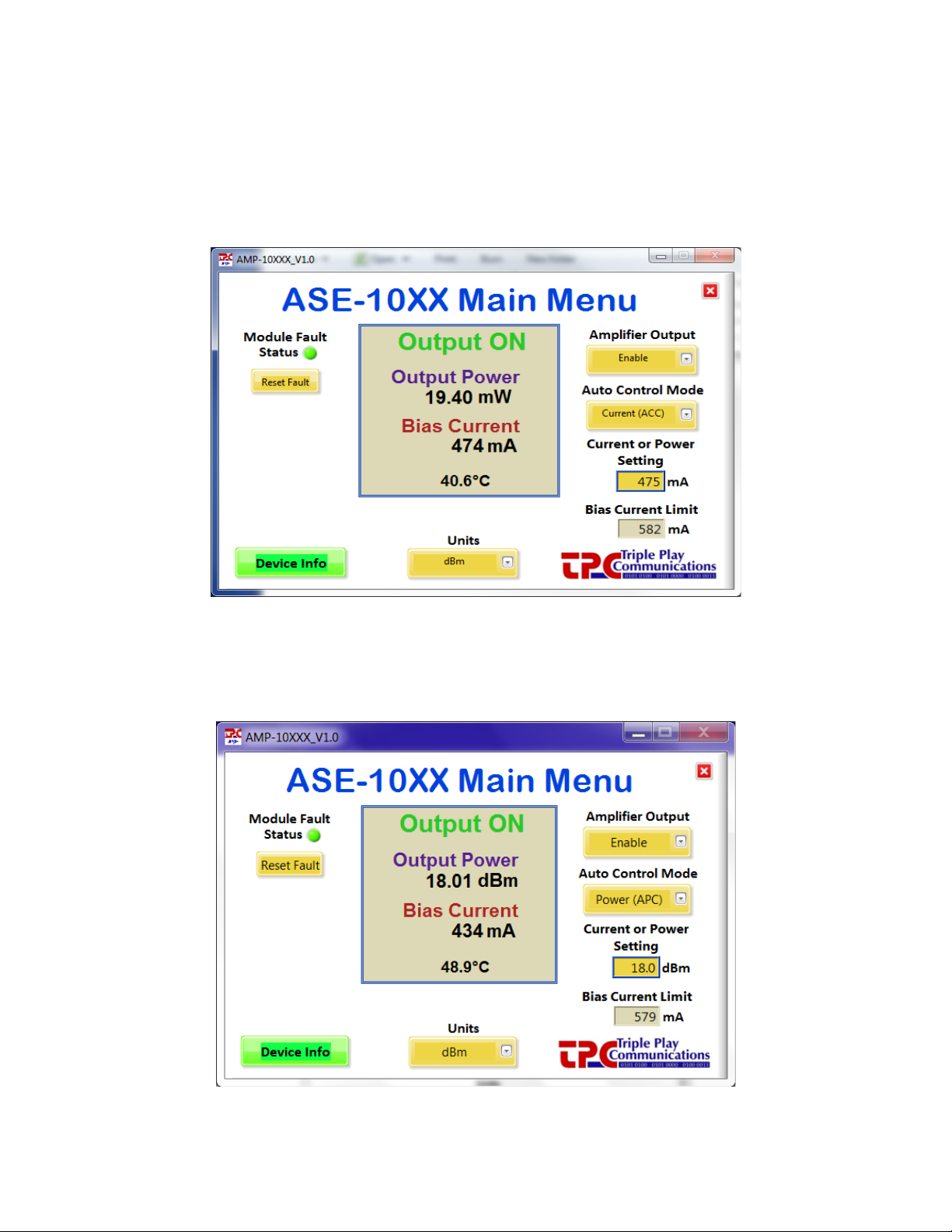
17
This amplifier module can operate in either Automatic Current Control (ACC) or Automatic Power
Control (APC) mode as selected by the user from the appropriate dropdown menu. When ACC is
selected, the user must enter the target bias current setting which ranges from 0 mA to the Bias
Current Limit shown in the lower-right corner. Once the user types in the target bias current and
presses Enter, the module is commanded to provide that specific bias current to the amplifier as
shown in Figure 7.2.2-2. The internal amplifier has a bias current setting accuracy of ±10% so the
bias current displayed in the main menu can have a variation of up to ±10% compared to the user
entered bias current setting.
Figure 7.2.2-2 - ACC Mode with a User Entered Setting of 475 mA for the Bias Current
When APC mode is selected the user must enter the target output power setting in units of dBm.
An example of APC mode is shown in Figure 7.2.2-3, in this case the user has entered a target
output power of +18.0 dBm.
Figure 7.2.2-3 - APC Mode with a User Entered Setting of +18.0 dBm for the Output Power

18
The Module Fault Status indication is shown in the GUI window as well as the LED located on the
top side of the module. The Module Fault Status is a logical OR of several alarms which are laser
bias current exceeds the maximum current limit, laser pump temperature out of valid operating
range, laser driver current limit reached, and laser driver junction temperature limit reached. If any
of these conditions occur, the Module Fault Status indication will alarm (Red). These four
conditions indicate a problem with the laser and will cause an automatic laser shutdown (ALS). To
clear an ALS condition, the user must click the Reset Fault button. If the fault condition will not
clear, please contact us (TPC) since a hardware failure may have occurred.
8.0 Ethernet Browser GUI Operation
As mentioned previously, the ASE-1019 module includes embedded web pages as part of its
internal microcontroller’s firmware. Standard HTML browsers such as Chrome, Firefox, and
Internet Explorer can be used to provide control and status of the module. After completing the
Ethernet port setup for operation with a standalone local computer or with an Ethernet Router
(Tables 5.1-1, 5.1-2, or 5.1-3), the ASE-1019 module can be controlled and monitored using the
steps described in paragraphs 8.1 through 8.4.
8.1
Optical Control/Status
8.1.1 Display of Status Parameters
Use a standard browser such as Chrome, Firefox, or Internet Explorer to communicate with the
ASE-1019 module by typing the appropriate IP address (e.g. 192.168.1.234) in the URL window of
the browser as shown in Figure 8.1.1-1.
Type appropriate IP address in URL window
Figure 8.1.1-1 - Type Appropriate IP Address of Module to Access Home Page
Click on the Optical Control/Status area of the menu bar to access the page which shows all the
real time status parameters and allows for control of optical functions. An example of the Optical
Control and Status window is given in Figure 8.1.1-2.

19
Figure 8.1.1-2 - Optical Control and Status Page
The key ASE-1019 module status parameters of bias current, maximum bias current limit, output
power, and temperature are obtained from the module and displayed in prominently in the upper
area of this window.
The total optical output power is monitored using a 1% tap to minimize insertion loss. The
calculated value is displayed in its designated location and can be shown in either dBm or Watts
based on the user’s selection of Units. Figure 8.1.1-3 shows Watts being selected by the user and
the appropriate output power level being displayed.

20
User selects Watts
Power is
displayed in Watts
Figure 8.1.1-3 – User Selects Watts to be Used for Displaying Output Power
If the output is disabled, the output power monitor will display -35 dBm. A temperature sensor is
mounted on the PCB and its value in degrees Celsius is continuously updated on the display.
This amplifier module can operate in either Automatic Current Control (ACC) or Automatic Power
Control (APC) mode as selected by the user from the appropriate dropdown menu. When ACC is
selected, the user must enter the target bias current setting which ranges from 0 mA to the Bias
Current Limit shown in the second row of status. Once the user types in the target bias current and
presses Enter, the module is commanded to provide that specific bias current to the amplifier as
shown in Figure 8.1.1-4. The internal amplifier has a bias current setting accuracy of ±10% so the
bias current displayed in the first row of status can have a variation of up to ±10% compared to the
user entered bias current setting.
User selects ACC from
dropdown menu, enters
desired bias current,
475 mA in this case, then
presses Enter
Figure 8.1.1-4 - ACC Mode with a User Entered Setting of 475 mA for the Bias Current
Table of contents


