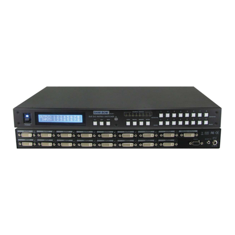
Tripp Lite B126-2X2 User manual

1
Owner’s Manual
HDMI Over Cat5
Matrix Switch
Models: B126-2X2, B126-4X4
1111 W. 35th Street, Chicago, IL. 60609 • www.tripplite.com/support
Copyright © 2013 Tripp Lite. All rights reserved.
Package Contents 2
Product Features 2
Mounting 4
Standard Installation 5
Remote Repeater Installation 7
RS232 Serial Control 10
Troubleshooting 13
Warranty & Warranty Registration 15
WARRANTY
REGISTRATION
Register online today for a
chance to win a FREE Tripp Lite
product www.tripplite.com/warranty
13-11-140 93-32BB.indd 1 11/19/2013 4:57:38 PM

2
Package Contents
Product Features
• B126-2X2orB126-4X4LocalTransmitterUnit
• ExternalPowerSupply
(Input:100-240V,50/60Hz,0.5AOutputB126-2X2:5V,2A;
OutputB126-4X4:5V,3A)
• 3.5mmtoDB9AdapterCable
• MountingHardware
• RemoteControl
• Owner’sManual
• SharemultipleHDMIsourcesbetweenmultiplemonitors
• Allowsanyinputtoberoutedtoanyoutput;orthesameinputtobe
routed to multiple outputs
• TransmitsthesignaloveroneCat5e/6cabletoaremotemonitorupto
175ft.away
• AB126-Seriesremotereceiverisneededateachmonitor
• Forlongerdistances:UseaB126-1A0orB126-1A0-WP-1active
remotereceivertoextenda1080p@60Hzsignalupto125ft.from
thetransmitter(ora1080i@60Hzsignalupto175ft.fromthe
transmitter)
• Forshorterdistances:UseaB126-1P0orB126-1P0-WP-1passive
remotereceivertoextenda1080p@60Hzsignalupto50ft.from
thetransmitter(ora1080i@60Hzsignalupto75ft.fromthe
transmitter)
• Use24AWG,SolidWireCat5e/6cable,suchasTrippLite’s
N202-Series,toachievemaximumdistanceandresolution
• Furtherexpandtherangeandnumberofmonitorsbyadding
B126-110remoterepeaterunits
13-11-140 93-32BB.indd 2 11/19/2013 4:57:38 PM

3
Product Features
• Adduptothreerepeatersoneachchannelofthematrixswitch,fora
totalof4displaysperchannel(Anactiveremotereceivershouldbethe
lastunitinachannel)
• A1080p@60Hzsignalcanbeextendedupto125ft.foreach
repeateraddedintoachannel(orupto175ft.fora1080i@
60Hzsignal)
• Switchbetweeninputsviapushbuttons,remotecontrol,
orRS232serial
• HDCP-compatible
• Mountinghardwareincluded
• Plug-and-play;nosoftwareordriversrequired
• Compatiblewithalloperatingsystems
• CompliantwiththeFederalTradeAgreementsAct(TAA)forGSA
Schedulepurchases
Optional Accessories:
• B126-1A0orB126-1A0-WP-1–ActiveRemoteReceiverUnits
• B126-1P0orB126-1P0-WP-1–PassiveRemoteReceiverUnits
• B126-110HDMIOverCat5Extender–RemoteRepeaterUnit
• N202-SeriesCat624AWG,SolidWirePatchCables
• P568-SeriesHigh-SpeedHDMICables
• P520-006RS-232SerialExtensionCable
13-11-140 93-32BB.indd 3 11/19/2013 4:57:38 PM

4
Mounting
TheB126-2X2andB126-4X4comewithmountinghardwarethatallows
themtobemountedinavarietyofways.Thefollowingimagesshow
thedifferentwaystheincludedmountingbracketscanbeattachedfor
different mounting methods.
Note: The images below show a B126-1A1 HDMI over Cat5 Receiver Unit, but the mounting
hardware installation is the same for the B126-2X2 and B126-4X4.
Wallmount 1 Wallmount 2
19” Rackmount Pole Mount
13-11-140 93-32BB.indd 4 11/19/2013 4:57:39 PM

5
Standard Installation
Note:
1. Test to make sure that the entire installation works properly before pulling cables through
ceilings/walls.
2. 24AWG, Solid Wire Cat5e/6 cable, such as Tripp Lite’s N202-Series, is required to achieve
maximum distance and resolution.
3. The diagram below shows a B126-2X2 installation, but installation will be the same for the
B126-4X4, except for the number of ports.
4. The back panel of the B126-4X4 contains an IR port which has been capped off. This port is
intended for future use, and does not currently function.
B126-2x2
Computer
Blu-Ray™
Cable Box
or DVR
B126-1P0
B126-1A0
Up to 125 ft. at 1080p @ 60Hz
Up to 175 ft. at 1080i @ 60Hz
Up to 50 ft. at 1080p @ 60Hz
Up to 75 ft. at 1080i @ 60Hz
1 Makesurealldevicesbeingconnectedareturnedoff.
2Optional:Connectthe3.5mmtoDB9adaptertotheRS232serial
portontheswitch,andthentotheDB9serialportonthecomputer
youwillbeusingtocontrolitwith.
3 ConnecttherstHDMIsourcetotheportontheswitchmarkedSource A.
4 Repeatstep3toconnectadditionalHDMIsourcestotheremainingports.
5 Connecttheexternalpowersupplytotheswitchandplugitintoa
TrippLiteSurgeSuppressor,PowerDistributionUnit(PDU),or
UninterruptiblePowerSupply(UPS).Whenreceivingpower,thefollowing
LEDswillilluminate:TheGreenPowerLED,TheOrangeSourceLEDs
(for the Sourceportsthathavedevicesconnectedtothem),andthe
GreenRJ45Output LEDs.AGreenLEDwillalsoilluminatetoindicate
thesourcethatisbeingtransmittedtoeachOutput port.
6 UsingCat5e/6cable,connecttheRJ45portmarkedOutput 1 to a
B126-Seriesremotereceiverunit.
13-11-140 93-32BB.indd 5 11/19/2013 4:57:40 PM

6
Standard Installation
7 Repeatstep6toconnectadditionalB126-Seriesremotereceiver
units to the remaining ports.
8B126-1A0 and B126-1A0-WP-1 only:Connecttheexternalpower
supplytotheactiveremotereceiverunit,andplugitintoaTrippLite
SurgeSuppressor,PDUorUPS.Whenreceivingpower,theGreen
RJ45LEDontheB126-1A0,andtheGreenPowerLEDonthe
B126-1A0-WP-1,willilluminate.
9 Repeatstep8foreachadditionalactiveremotereceiverunitinthe
installation.
10
ConnecttheremotereceiverunittoamonitorusingaTrippLiteP568-
SeriesHigh-SpeedHDMIcable.IfyouhaveaB126-1P0,connectits
built-inHDMIconnectortoamonitor.Whenconnectedtoand
receivingpowerfromamonitor,theGreenRJ45LEDontheB126-1P0,
andtheGreen PowerLEDontheB126-1P0-WP-1,willilluminate.
11
Repeat step 10 for each additional remote receiver unit in the
installation.
12
Turnonthepowertotheconnecteddevices.TheOrangeRJ45LEDs
ontheB126-2X2,B126-4X4andB126-1A0,andtheOrangeActivity
LEDontheB126-1A0-WP-1,willilluminate.Thevideoimageshould
nowbedisplayedontheconnectedmonitors.
13
B126-1A0andB126-1A0-WP-1only:Ifnecessary,usethe
Equalization control to adjust the video image.
Note: An improper Equalizationsetting can cause the monitor not to display an image at all.
Try each setting until an acceptable image is displayed.
14
Presstheswitchnexttoeachsetof Output LEDstoswitchthesource
beingdisplayedonthecorrespondingOutput monitor. You can also
usetheincludedremotecontroltoswitchbetweensources.Aswith
theswitchnexttotheOutputLEDs,pressthebuttonontheremote
control of the desired Outputporttoswitchthesourcebeingdisplayed.
Note: The same 4 button remote control comes with both the B126-2X2 and B126-4X4.
Buttons 3 and 4 will not be used for the B126-2X2.
SeetheRS232 Serial Control section in this manual for details on
controllingtheswitchusingTerminalEmulationSoftware.
13-11-140 93-32BB.indd 6 11/19/2013 4:57:41 PM

7
Remote Repeater Installation
Note:
1. Test to make sure that the entire installation works properly before pulling cables through
ceilings/walls.
2. 24AWG, Solid Wire Cat5e/6 cable, such as Tripp Lite’s N202-Series, is required to achieve
maximum distance and resolution.
3. The diagram below shows a B126-2X2 installation, but installation will be the same for the
B126-4X4, except for the number of ports.
4. The back panel of the B126-4X4 contains an IR port which has been capped off. This port is
intended for future use, and does not currently function.
B126-2x2
B126-110 B126-110 B126-110
Up to 175 ft. at 1080i @ 60Hz
Up to 125 ft. at 1080p @ 60Hz
B126-1A0-WP-1
B126-110 B126-110 B126-110
Up to 175 ft. at 1080i @ 60Hz
Up to 125 ft. at 1080p @ 60Hz
Blu-Ray™
Cable Box
or DVR
B126-1A0
0
1
2
3
4
5
6
7
0
1
2
3
4
5
6
7
0
1
2
3
4
5
6
7
0
1
2
3
4
5
6
7
0
1
2
3
4
5
6
7
0
1
2
3
4
5
6
7
Computer
1 Makesurealldevicesbeingconnectedareturnedoff.
2Optional: Connectthe3.5mmtoDB9adaptertotheRS232serial
portontheswitch,andthentotheDB9serialportonthecomputer
youwillbeusingtocontrolitwith.
3 ConnecttherstHDMIsourcetotheportontheswitchmarked
Source A.
4 Repeatstep3toconnectadditionalHDMIsourcestotheremaining
ports.
13-11-140 93-32BB.indd 7 11/19/2013 4:57:42 PM

8
Remote Repeater Installation
5 Connecttheexternalpowersupplytotheswitchandplugitintoa
TrippLiteSurgeSuppressor,PDU,orUPS.Whenreceivingpower,
thefollowingLEDswillilluminate:TheGreenPowerLED,theOrange
Source LEDs(fortheSource ports that have devices connected
tothem),andtheGreenRJ45 OutputLEDs.AGreenLEDwillalso
illuminatetoindicatethesourcethatisbeingtransmittedtoeach
Output port.
6 UsingCat5e/6cable,connecttheRJ45portmarked Output 1 to the
RJ45inputportofaB126-110remoterepeaterunit.
7 ConnectamonitortotheHDMIoutputportontherepeaterusinga
TrippLiteP568-SeriesHigh-SpeedHDMIcable.
8 Connecttheexternalpowersupplytotherepeaterandplugitinto
aTrippLiteSurgeSuppressor,PDUorUPS.TheGreenPowerLED
andtheGreenRJ45LEDsilluminatetoindicatetheunitisreceiving
power.
Adduptothreerepeatersperchannel,foratotalof4displays(an
active remote receiver should be the last unit in a channel). To connect
additionalrepeaters,proceedtostep9.Tonishyourinstallationwitha
B126-1A0orB126-1A0-WP-1receiver,proceedtostep12.
9 UsingCat5e/6cable,connecttheRJ45outputportontherst
repeatertotheRJ45inputportonasecondrepeater.
10
ConnectamonitortotheHDMIoutputportontherepeaterusinga
TrippLiteP568-SeriesHigh-SpeedHDMIcable.
11
Connecttheexternalpowersupplytotherepeaterandplugitinto
aTrippLiteSurgeSuppressor,PDUorUPS.TheGreenPowerLED
andtheGreenRJ45LEDsilluminatetoindicatetheunitisreceiving
power.
Toaddathirdrepeater,repeatsteps9through11.Tonishyour
installationwithaB126-1A0orB126-1A0-WP-1receiver,proceedto
step 12.
13-11-140 93-32BB.indd 8 11/19/2013 4:57:42 PM

9
Remote Repeater Installation
12
UsingCat5e/6cable,connecttheRJ45outputportonthelast
repeatertotheRJ45inputportonaB126-1A0orB126-1A0-WP-1
receiver.
13
ConnectamonitortotheHDMIoutputportonthereceiverusinga
TrippLiteP568-SeriesHigh-SpeedHDMIcable.
14
Connecttheexternalpowersupplytotheactiveremotereceiverunit,
andplugitintoaTrippLiteSurgeSuppressor,PDU,orUPS.When
receivingpower,theGreenRJ45LEDontheB126-1A0,andthe
GreenPower LEDontheB126-1A0-WP-1,willilluminate.
Repeatsteps6through14fortheremainingOutput ports on the switch.
15
Turnonpowertotheconnecteddevices.TheOrangeRJ45LEDs
ontheB126-2X2,B126-4X4,B126-110,andB126-1A0,andthe
OrangeActivityLEDontheB126-1A0-WP-1,willilluminate.Thevideo
imageshouldnowbedisplayedontheconnectedmonitors.
16
Ifnecessary,usetheEqualization control on the repeater and receiver
units to adjust the video image.
Note: An improper Equalization setting can cause the monitor not to display an image at all.
Try each setting until an acceptable image is displayed.
17
PresstheswitchnexttoeachsetofOutputLEDstoswitchthe
sourcebeingdisplayedonthecorrespondingOutput monitor. You
canalsousetheincludedremotecontroltoswitchbetweensources.
AswiththeswitchnexttotheOutputLEDs,pressthebuttononthe
remote control of the desired Outputporttoswitchthesourcebeing
displayed.
Note: The same 4 button remote control comes with both the B126-2X2 and B126-4X4.
Buttons 3 and 4 will not be used for the B126-2X2.
SeetheRS232 Serial Control section in this manual for details on
controllingtheswitchusingTerminalEmulationSoftware.
13-11-140 93-32BB.indd 9 11/19/2013 4:57:42 PM

10
RS232 Serial Control
BeforeusingRS232SerialControl,youmustrstgointoyouTerminal
EmulationSoftwareandupdatetheCOMportsettings.
1 GototheSetupdrop-downmenuandselecttheSerial Port option.
2 SelecttheCOMportthatisbeingused,andupdatetheremaining
settingsasfollows:BaudRate(57600),Data(8bit),Parity(none),
Stop(1bit),FlowControl(none).
13-11-140 93-32BB.indd 10 11/19/2013 4:57:42 PM

11
RS232 Serial Control
3 Next,youwillneedtocongureyoursoftwaretoallowinputcontrol.
GototheSetupdrop-downmenuandselecttheTerminal option.
4 Updatethefollowingsettings;Receive(LF),LocalEcho(enable).The
remaining settings can stay as they are.
13-11-140 93-32BB.indd 11 11/19/2013 4:57:42 PM

12
RS232 Serial Control
5 Oncethesesettingsareupdated,theTerminalEmulationSoftware
willrecognizetheswitch,allowingyoutoentercommandstocontrolit
with.Thefollowingtableliststheavailablecommands.
Command Action
sw[x][n] Switchesthesourcebeingdisplayedontheselected
output.[x]istheoutput(1,2,3,or4)and[n]isthe
desiredsource(A,B,C,orD).Forexample,acommand
of sw1 A would display source A on output 1.
PWD Turns power to the switch on/off.
STE Displaysthecurrentoutputstate,showingwhichsource
isbeingdisplayedoneachoutput.
13-11-140 93-32BB.indd 12 11/19/2013 4:57:42 PM

13
Troubleshooting
Ifyouareunabletogetanacceptableimageafterfollowingthe
installationinstructions,trythetroubleshootingtipsbelow.
1 Aretheexternalpowersuppliesthatcamewiththeproduct
connectedandpluggedintoaworkingpowersource?Fortheproduct
tofunctionproperly,itmustbeconnectedtoandreceivingpower
fromtheexternalpowersupply.
2 Wasthepowertotheconnecteddevicesturnedoffpriorto
installation?Ifnot,restartthem.
3 HaveyouadjustedtheEqualizationsettingontherepeaterand/or
receiverunits?Therearebuilt-inEqualizationadjustmentknobson
everyrepeaterandactivereceiver,whichcanbeadjustedtoobtain
thebestpicturequality.Usetheminiscrewdriverincludedwiththe
producttoadjustthissettinguntilanacceptableimageisdisplayed.
Note: An improper Equalization setting can cause the monitor not to display an image at all.
Try each setting until an acceptable image is displayed.
4 Whatresolutionareyoutryingtoreach?TrippLite’sHDMIoverCat5
extendersaretestedtosupportupto1080p@60Hzvideoresolution.
SeetheProduct Features section or the installation diagrams in this
manualfordetailsonmaxdistanceandresolutionwhenusingthe
repeaterandthedifferentreceivers.Theshortertheextensiondistance,
thehighertheresolutionyouwillbeabletoobtain.Ifyouarenotable
togetanacceptableimageafteradjustingtheEqualizationsetting,try
loweringyourcomputer’svideoresolutionoradjustingtherefreshrate.
5 Whattypeofcablingareyouusing?Inferiorcablingcanresultinpoor
performance,soitisimportantthatyouusecablesthatcansupport
thevideoresolutionyouaretryingtoobtain.Toachievemaximum
distanceandresolution,24AWGsolidwireUTPcablemustbeused.
TrippLite’sN202-SeriesCat6cablesaremadewith24AWGsolid
wire,asaretheN022-01K-GY(Cat5)andN222-01K-GYbulkcables.
Also,theHDMIcablesyouareusingmustsupporttheresolutionyou
aretryingtoobtain.Inexpensive,lowqualityHDMIcablesmaynot
supportthemaximumresolution.Itisrecommendedthatyouuse
TrippLite’sP568-SeriesHigh-SpeedHDMIcables,astheyhavebeen
testedtoworkwiththeB126-Seriesextenderproducts.
13-11-140 93-32BB.indd 13 11/19/2013 4:57:42 PM

14
Troubleshooting
6 Testyourcablestoensuretheyareworkingproperly.Forexample,
connectyourHDMIcablesbetweenasourceandmonitorthatyou
knowworkstoseeifthecableisfunctioning.ForCat5e/6cable,
connectitbetweenacomputerandanetworktoverifythatit
establishesanetworkconnection.
7 Doyouhaveanypatchpanelsorotherdevicesinbetweenthe
transmitter,repeater,andreceiverunits?TrippLite’sHDMIoverCat5
extenderproductsweredesignedtobeconnecteddirectlyfromthe
transmittertotherepeaterand/orreceiverviaUTPcable.Themore
connectionpointsthatareinbetweenthesourceandtheremote
monitor,themorelikelyitwillbethatsignaldegradationwilloccur,
causing poor performance. If you have a patch panel or other device
inbetween,itshouldberemovedfromtheinstallation.
8 Checkyourcablingforanydamagesthatmayhaveoccurredduring
installation.Ifacableconnectorisloosenedfrompullingthrough
ceilings/walls,orthecablejacketisdamagedcausingthewiringtobe
exposed,youwillnotbeabletoachievemaximumperformance.
9 Arethetransmitter,repeater,and/orreceiverlocatedinanareathat
exposesthemtohighertemperatures?Iftheproductisoverheated,it
will not function properly.
10
IfyouarehavingtroublegettingyourTerminalEmulationSoftwareto
recognizetheswitch,youmayneedtoshutdownyourinstallationand
startfromthebeginning.The3.5mmtoDB9adaptercablemustbe
connectedrst;otherwisetheswitchwillnotberecognized.
11
IfyourarestillhavingtroublegettingyourTerminalEmulation
Softwaretorecognizetheswitch,checktomakesurethatyourserial
settings are set according to the instructions in the RS232 Serial
Control section of this manual.
13-11-140 93-32BB.indd 14 11/19/2013 4:57:43 PM

15
Warranty & Warranty Registration
1-Year Limited Warranty
TRIPPLITEwarrantsitsproductstobefreefromdefectsinmaterialsandworkmanshipforaperiod
ofone(1)yearfromthedateofinitialpurchase.TRIPPLITE’sobligationunderthiswarrantyis
limitedtorepairingorreplacing(atitssoleoption)anysuchdefectiveproducts.Toobtainservice
underthiswarranty,youmustobtainaReturnedMaterialAuthorization(RMA)numberfrom
TRIPPLITEoranauthorizedTRIPPLITEservicecenter.ProductsmustbereturnedtoTRIPPLITE
oranauthorizedTRIPPLITEservicecenterwithtransportationchargesprepaidandmustbe
accompaniedbyabriefdescriptionoftheproblemencounteredandproofofdateandplaceof
purchase.Thiswarrantydoesnotapplytoequipmentwhichhasbeendamagedbyaccident,
negligenceormisapplicationorhasbeenalteredormodiedinanyway.
EXCEPTASPROVIDEDHEREIN,TRIPPLITEMAKESNOWARRANTIES,EXPRESSORIMPLIED,
INCLUDINGWARRANTIESOFMERCHANTABILITYANDFITNESSFORAPARTICULARPURPOSE.
Somestatesdonotpermitlimitationorexclusionofimpliedwarranties;therefore,theaforesaid
limitation(s)orexclusion(s)maynotapplytothepurchaser.
EXCEPTASPROVIDEDABOVE,INNOEVENTWILLTRIPPLITEBELIABLEFORDIRECT,INDIRECT,
SPECIAL,INCIDENTALORCONSEQUENTIALDAMAGESARISINGOUTOFTHEUSEOFTHIS
PRODUCT,EVENIFADVISEDOFTHEPOSSIBILITYOFSUCHDAMAGE.Specically,TRIPPLITE
isnotliableforanycosts,suchaslostprotsorrevenue,lossofequipment,lossofuseof
equipment,lossofsoftware,lossofdata,costsofsubstitutes,claimsbythirdparties,or
otherwise.
FCC Notice, Class B
Thisdevicecomplieswithpart15oftheFCCRules.Operationissubjecttothefollowingtwo
conditions:(1)Thisdevicemaynotcauseharmfulinterference,and(2)thisdevicemustaccept
anyinterferencereceived,includinginterferencethatmaycauseundesiredoperation.
Note:ThisequipmenthasbeentestedandfoundtocomplywiththelimitsforaClassBdigital
device,pursuanttopart15oftheFCCRules.Theselimitsaredesignedtoprovidereasonable
protectionagainstharmfulinterferenceinaresidentialinstallation.Thisequipmentgenerates,
usesandcanradiateradiofrequencyenergyand,ifnotinstalledandusedinaccordancewith
theinstructions,maycauseharmfulinterferencetoradiocommunications.However,thereisno
guaranteethatinterferencewillnotoccurinaparticularinstallation.Ifthisequipmentdoescause
harmfulinterferencetoradioortelevisionreception,whichcanbedeterminedbyturningthe
equipmentoffandon,theuserisencouragedtotrytocorrecttheinterferencebyoneormoreof
the following measures:
•Reorientorrelocatethereceivingantenna.
•Increasetheseparationbetweentheequipmentandreceiver.
•Connecttheequipmentintoanoutletonacircuitdifferentfromthattowhichthereceiveris
connected.
•Consultthedealeroranexperiencedradio/TVtechnicianforhelp.
AnychangesormodicationstothisequipmentnotexpresslyapprovedbyTrippLitecouldvoidthe
user’sauthoritytooperatethisequipment.
13-11-140 93-32BB.indd 15 11/19/2013 4:57:43 PM

16
1111 W. 35th Street, Chicago, IL. 60609 • www.tripplite.com/support
13-11-14093-32BB_revC
WARRANTY REGISTRATION
Visitwww.tripplite.com/warrantytodaytoregisterthewarrantyforyournewTrippLiteproduct.
You’llbeautomaticallyenteredintoadrawingforachancetowinaFREETrippLiteproduct!*
*Nopurchasenecessary.Voidwhereprohibited.Somerestrictionsapply.Seewebsitefordetails.
WEEE Compliance Information for Tripp Lite Customers and Recyclers
(European Union)
UndertheWasteElectricalandElectronicEquipment(WEEE)Directiveand
implementingregulations,whencustomersbuynewelectricalandelectronicequipment
from Tripp Lite they are entitled to:
•Sendoldequipmentforrecyclingonaone-for-one,like-for-likebasis
(thisvariesdependingonthecountry)
•Sendthenewequipmentbackforrecyclingwhenthisultimatelybecomeswaste
WARNING
Useofthisequipmentinlifesupportapplicationswherefailureofthisequipmentcanreasonably
beexpectedtocausethefailureofthelifesupportequipmentortosignicantlyaffectitssafety
oreffectivenessisnotrecommended.Donotusethisequipmentinthepresenceofaammable
anestheticmixturewithair,oxygenornitrousoxide.
TrippLitefollowsapolicyofcontinuousimprovement.Productspecicationsaresubjecttochange
without notice.
Warranty & Warranty Registration
13-11-140 93-32BB.indd 16 11/19/2013 4:57:43 PM
Other manuals for B126-2X2
1
This manual suits for next models
1
Table of contents
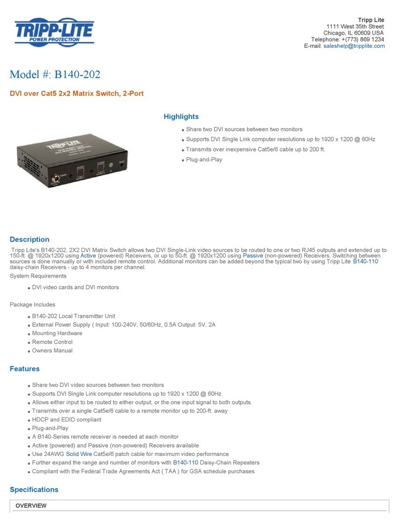
Other Tripp Lite Matrix Switcher manuals

Tripp Lite
Tripp Lite B140-202 User manual

Tripp Lite
Tripp Lite B300-9X2-4K User manual

Tripp Lite
Tripp Lite NetDirector B060-032 User manual

Tripp Lite
Tripp Lite B126-2X2 User manual

Tripp Lite
Tripp Lite B119-2X2 User manual

Tripp Lite
Tripp Lite B119-4X2-4K User manual

Tripp Lite
Tripp Lite NetDirector B060-016-2 User manual